14th European Signal Processing Conference (EUSIPCO 2006), Florence, Italy, September 4-8, 2006, copyright by EURASIP
SERIAL LDPC DECODING ON A SIMD DSP USING HORIZONTAL SCHEDULING Marco Gomes, Vitor Silva, Cláudio Neves and Ricardo Marques Institute of Telecommunications - Department of Electrical and Computer Engineering University of Coimbra, P-3030-290 Coimbra, Portugal phone: + 351 239 79 62 36, fax: + 351 239 79 62 93 email:
[email protected],
[email protected],
[email protected],
[email protected]
ABSTRACT In this paper we propose an ef cient vectorized low density parity check (LDPC) decoding scheme based on the min-sum algorithm and the horizontal scheduling method. Also, the well known forward-backward algorithm, used in the check-node messages update, is improved. Results are presented for 32 and 16 bits logarithm likelihood ratio messages representation on a high performance and modern xed point DSP. The single instruction multiple data (SIMD) feature was explored in the 16 bits case. Both regular and irregular codes are considered. 1. INTRODUCTION Owing to their outstanding performance, low-density parity check codes (LDPC) are recognized to be one of the best classes of codes which approach the Shannon limit efciently.They were rst proposed by Robert Gallager [1], [2], in the 1960´s, based on sparse binary matrices and ef cient message-passing decoding algorithms (belief propagation and bit- ipping).Their rediscover by MacKay and Neal [3] led to a growing interest on research and development of ef cient LDPC coding solutions for digital communication and storage systems [4], [5]. A LDPC code is characterized by a parity check matrix, H, with a low density of 1's. As any linear block code, a LDPC code can also be represented by a Tanner graph (TG) [6]. This bipartite graph is formed by two types of nodes. The check nodes (CN), one per each code constraint, and the bit nodes (BN), one per each bit of the codeword, with the connections between them given by H. The H matrix of regular LDPC codes presents a uniform row and column weight structure, which can represent an advantage in the design of an iterative decoder. Yet, irregular LDPC codes are shown to have a better performance [7]. The sum product decoding algorithm (SPA) [1] applied to LDPC codes is known to have the best performance. The aim of SPA algorithm is to compute iteratively the a posteriori probability (APP) of each codeword bit to be 1 (or 0) considering that all parity check constraints are satis ed . The iterative procedure is based on an exchange of messages between the BN's and CN's of the Tanner graph, containing believes about the value of each codeword bit. These messages (probabilities) can be represented rigorously in their domain or, more compactly, using logarithm likelihood ratios. Due to the high computational complexity, the log-likelihood ratio form of SPA and its simpli cations are preferred, namely, the min-sum algorithm [8]. We will follow this approach. Usually, the message-passing is based on the so-called “ ooding schedule” i.e., the messages sent by BN's are updated all together (in a serial or parallel manner) before CN's
messages could be updated and, vice versa. Recently, and motivated by the question of whether it would be possible to improve the velocity of convergence and the performance of the iterative decoding algorithms, new message-passing schedules have been proposed [9], [10], [11]. One of the novel approaches is horizontal scheduling [10]. The main idea is to use the fresh calculated information as soon as it is available. So, in horizontal scheduling the information sent to a CN under process takes in account not only the information of the previous iteration, but also, all the information from the current iteration that has been updated by the previous processed CN's. Since each CN receives all up-to-date information, the new messages sent by that CN tend to be more reliable which accelerates the convergence of the algorithm. The parallel nature of the ooding schedule is not very important when we use a digital processor. Thus, a serial and faster message scheduling is preferable. The simplicity of the operations involved in the min-sum algorithm (sum's and min's), is suitable for a fast xed point digital signal processor (DSP), which constitutes, for medium length LDPC codes, a good and exible decoding alternative to the expensive and specialized hardware decoding solutions. Furthermore, experimental results have shown that the min-sum loses no performance under message quantization with more than 4 bits [12]. Last generation of xed point digital signal processors (DSP) contains a powerful set of single instruction multiple data (SIMD) operations which allow the processing of multiple data in a single instruction. In order to take full advantage of all the capacities of modern DPS's, ef cient vectorized decoding approaches have to be developed. In this paper, we propose, 32 and 16 bits, vectorized solutions for LDPC decoding using the min-sum algorithm and horizontal scheduling. In section 2, we present a brief review of the min-sum algorithm following the traditional ooding schedule approach. The advantages of the serial check node processing (horizontal scheduling) are discussed and the method is presented. Next, an improved forward-backward method is developed in section 3. In section 4 ef cient and generic vectorized LDPC decoding solutions (16 and 32 bits) are developed for a modern xed point SIMD DSP. Finally, in section 5, the experimental results are reported. 2. THE MIN-SUM ALGORITHM The min-sum algorithm [8] is a simpli ed version of the SPA [1], [2] in the logarithmic domain, where multiplications are replaced by additions (less demanding). Consequently, the processing load in check nodes decreases signi cantly with just a small loss in performance.
14th European Signal Processing Conference (EUSIPCO 2006), Florence, Italy, September 4-8, 2006, copyright by EURASIP
Given a (N; K) LDPC code, we assume BPSK modulation which maps a codeword, c = (c1 ; c2 ; ; cN ) , onto the sequence, x = (x1 ; x2 ; ; xN ), according to xi = ( 1)ci . Then, the modulated vector x is transmitted through an additive white Gaussian noise (AWGN) channel. The received sequence is y = (y1 ; y2 ; ; yN ) , with yi = xi + ni , where ni is a random gaussian variable with zero mean and variance, N0 =2. We denote the set of bits that participate in check m by N (m) and, similarly, we de ne the set of checks in which bit n participates as M (n). We also denote N (m) nn as the set N (m) with bit n excluded and, M (n) nm as the set M (n) with check m excluded. Denoting the log-likelihood ratio (LLR) of a random variable as, L (x) = ln (p(x = 0)=p(x = 1)), we designate: LPn - The a priori LLR of BNn , derived from the received value yn ; Lrmn - The message that is sent from CNm to BNn , computed based on all received messages from BN's N (m) nn. It is the LLR of BNn , assuming that the CNm restriction is satis ed; Lqmn - The LLR of BNn , which is sent to CNm , and is calculated, based on all received messages from CN's M (n) nm and the channel information, LPn ; LQn - The a posteriori LLR of BNn . 2.1 Traditional ooding-schedule The min-sum algorithm following the so-called “ ooding schedule” is carried out as follows: For each node pair (BNn , CNm ), corresponding to hmn = 1 in the parity check matrix H of the code do: Initialization:
2yn . (1) σ2 The factor 2=σ 2 can be omitted without any performance loss [8], thus no a priori information about the AWGN channel is required, i.e., Lqnm = LPn = yn . Lqnm = LPn =
Iterative body: I. Calculate the log-likelihood ratio of message sent from CNm to BNn : Lrmn =
∏
n0 2N(m)nn
where and
α n0 m
min β n0 m ,
n0 2N(m)nn
(2)
α nm , sign (Lqnm ) ,
(3)
β nm , jLqnm j .
(4)
II. Calculate the log-likelihood ratio of message sent from BNn to CNm : Lqnm = LPn +
∑
m0 2M(n)nm
Lrm0 n .
(5)
III. Compute the a posteriori pseudo-probabilities and perform hard decoding: LQn = LPn +
∑
m0 2M(n)
Lrm0 n ,
(6)
8n; cˆn =
1 0
( (
LQn < 0 . LQn > 0
(7)
The iterative procedure is stopped if the decoded word veries all parity check equations of the code (^ c HT = 0) or the maximum number of iterations is reached. 2.2 Horizontal scheduling It is well known that SPA and min-sum, following the traditional ooding-schedule message updating rule, are optimum APP decoding methods when applied to codes described by TG's without cycles [14]. However, good codes always have cycles and the short ones tend to degrade the performance of the iterative message passing algorithms (results far from optimal). Motivated by the referred problem and the speed up convergence goal, new message-passing schedules have been proposed [9], [10], [11]. Considering ooding-schedule, the messages sent by BN's are updated all together (in a serial or parallel manner) before CN's messages could be updated and, vice versa. At each step, the messages used in the computation of a new message, are all from the previous iteration. A different approach is to use new information as soon as it is available, so that, the next node to be updated could use more up-to-date (fresh) information. For example, this can be done following two different strategies know by horizontal and vertical scheduling with a considerable processing gain in the number of iterations to reach a valid codeword [10]. Vertical-schedule operates along the BN's while horizontal schedule operates along CN's. Both schedules are serial, i.e., the nodes are processed sequentially, one after the other. The computational complexity of the ooding and serial schedules is similar. However, from a DSP point of view, horizontal-schedule is preferable to vertical-schedule, as it will be described next. Observing equations (5) and (6) we note that the message sent from BNn to CNm , can easily be obtained by Lqnm = LQn
Lrmn .
(8)
Consequently, we only have to keep in memory LQn and Lrmn messages, because according with (2), the val(i 1) ues of Lqnm , with n 2 N (m), needed to compute the new (i) Lrmn messages, sent by CNm at iteration i, can be obtained (i 1) (i 1) from values, LQn and Lrmn , of the previous iteration, as (i 1) shown in (8). The old Lrmn values are replaced by the new (i) ones, Lrmn , at the end of CNm updating process. Processing BN's in a serial manner, following the so called vertical-schedule, means that after processing each BN, says BNn , all CN's connected to it, i.e. CN's m 2 M (n), must re ect the current BNn actualization. Thus, for each CN m 2 M (n), all messages Lrmn0 , with n0 2 N (m) nn, must be updated according with the new received message Lqnm from BNn . This represents a higher processing burden in comparison to the horizontal-schedule approach, where the updating problem is solved by just actualizing the a posteriori LLR's, LQn , according to (8). Memory addressing problems are also simpli ed when using horizontal-schedule since after processing a CN, says CNm , only one value LQn per BN n 2 N (m), must be read (old LQn ) from memory and written (new updated LQn )
14th European Signal Processing Conference (EUSIPCO 2006), Florence, Italy, September 4-8, 2006, copyright by EURASIP
back to the same place. Considering vertical-schedule, after processing a BN, says BNn , a set of values Lrmn0 , with n0 2 N (m) nn, for each CN m 2 M (n), must be read, recalculated and written back to the same memory positions. Finally, the min-sum algorithm with horizontal-schedule is carried out as follows: For each node pair (BNn , CNm ), corresponding to hmn = 1 in the parity check matrix H of the code do: Initialization: LQn = LPn =
(9) (10)
Iterative body: I. Process each CN one after the other: Step 1: For the CNm , calculate the log-likelihood ratio of messages sent to BN n 2 N (m):
∏
n0 2N(m)nn
α n0 m
min β n0 m ,
n0 2N(m)nn
(11)
where α nm ,sign (Lqnm ) = sign (LQn and 0 Lrmn
β nm , jLqnm j = jLQn
A1 Ai
= Lqn1 m = Ai 1 Lqni m; i = 2; :::; k
Lrmn ) ,
Bk Bi
= Lqnk m = Bi+1 Lqni m; i = k
Lrmn j ,
0 Lrmn + Lrmn .
(13)
(14)
3. IMPROVED FORWARD BACKWARD METHOD The serial CN updating process (for the various messagepassing LDPC decoding algorithms) is normally carried out using an ef cient forward backward scheme [9], [15]. The procedure avoids the re-computation of common values to the various messages sent by one CN to all the BN's connected to it. Consider a CNm of weight k, and denote by ni , the i-th BN connected to it. The CN updating rule can be written as: Lqn0 m
(17)
Lrmn1 Lrmni Lrmnk
= B2 = Ai = Ak
1
Bi+1 ; i = 2; :::; k
1
(18)
1
Now, we will show that is possible to merge step 2 and 3 in just one iterative cycle, decreasing for a half their processing time. It is important to note that the Lqnm values are stored in memory (unless the CN's weights are very small and it is possible to keep them in CPU registers). Thus, they must be read in order to calculate Ai according to (16). After that, step 2 and 3 can be done jointly by simply reversing the Lrmni updating order. Consequently, the new algorithm is de ned as follows (with i = k; :::; 2): - Iteration k: At the begin of the backward pass it is already known Ak 1 and it was received the last BN message, Lqnk m , and so, calculate: Lrmnk Bk
= Ak 1 = Lqnk m
(19)
- Iteration k 1: Since Bk is already known from the previous iteration, calculate:
II. Perform hard decoding as in (7) and stopping if the decoded word ^ c veri es all parity check equations of the code (^ c HT = 0) or the maximum number of iterations is reached.
n0 2N(m)nn
1; :::; 2
(12)
Step 2: Update the a posteriori LLR of BNn .
Lrmn =
(16)
Step 2 (move backward):
with being the new calculated message to be sent from CNm to BNn , and Lrmn referring to the old message that was sent.
LQ0n = LQn
1
Step 3 (updating):
2yn , σ2
Lrmn = 0.
0 Lrmn =
Step 1 (move forward):
(15)
where the operation is algorithm dependent (for min-sum, a b , sign (a) sign (b) min (jaj ; jbj)). Traditionally, the forward backward method is seen as a three step iterative procedure:
Lrmnk Bk
1
1
= Ak = Bk .. .
2
Bk Lqnk 1 m
(20)
- Iteration 2: Since B3 is already known from the previous iteration, calculate: Lrmn2 Lrmn1
= A1 B3 = B2 = B3
Lqn2 m
(21)
4. VECTORIZED LDPC DECODING We developed useful 32 and 16 bits vectorized data structures for effective LDPC decoding on a DSP using the min-sum algorithm and horizontal scheduling. We choose the xed point TMS320C6416 [13], from Texas Instruments as the target device. However, the structure design is almost generic which means minor changes when implemented in a different processor. In order to improve signi cantly the decoding speed without any performance loss, the 16 bit version is carefully developed to use SIMD instructions.
14th European Signal Processing Conference (EUSIPCO 2006), Florence, Italy, September 4-8, 2006, copyright by EURASIP
indexed reading/writing 32-bit
Ind e LQ x of :a
2
Forward Step
Index LQak
A2
Lqa2
1
Ak-2 Lqa(k-1)
1
Ak-1 Lqak
Index LQb2 64-bit read
M
M
32-bit write
Compute: Bi = Bi+1 Lqnm L’ rmn = Ai-1 Bi+1 LQ’ rmn n = Lqnm + L’
32-bit write
Backward/Updating Step
Index of LQn
64-bit N(1) ; k = #N(1) ; k even ]
LQN-1 LQN
d
64-bit read
L
LQi
ea
CN1 [a1, a2, ... ak
L
LQ2
r it
Index LQa(k-1) Index LQak Lr1 a(k-1) Lr1 ak
LQ1
-b
Launch read of LQn and LQn+1
M
LQ structure
Compute: Lqnm = LQn – Lrmn Lq(n+1)m = LQ(n+1) – Lrm(n+1) Ai = Ai-1 Lqnm Ai+1 = Ai Lq(n+1)m
Forward Step 64-bit write 64-bit
sequential writing 1
Weight CN2 Index LQb1 Index LQb2 Lr2 b1 Lr2 b2
A1 A2
Weight CN3 Index LQc1 Index LQ c2 Lr3 c1 Lr3 c2
A3 A4
Ak-2 Ak-1
auxiliary structure
sequential reading 64-bit read
M
Index LQb(k’-2) Index LQ b(k’-1) Lr2 b(k’-2) Lr2 b(k’-1) Index LQbk’ Lr2 bk’
Lqa1
1
CN3
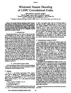
Based on the Tanner graph of the LDPC code, and the processing ow of the min-sum algorithm with horizontal scheduling, we created dynamic and vectorized data structures to represent all exchanged messages between connected nodes (BNn , CNm ) which allow us to reduce the required memory space and processing time, improving the computational ef ciency of the implemented decoding algorithms. Therefore, we created two data vector structures named by LQ and Lr (see g. 1), respectively, to store all LQn values, and all Lrmn messages sent from each CNm to its connected BN's. In order to compute the Lqnm messages according with (8) and, simultaneously, to reduce the number of memory reads by sequential data accessing (avoiding this way addressing overheads), we pack consecutively in Lr memory pairs of values Lrmn and the corresponding LQn indexes (pointers to LQ memory). In g. 1 is also possible to observe the mechanism of the improved two step forward and backward/updating algorithm. Both steps are iterative procedures. By using the CPU parallelism and proper programming techniques (namely, software pipelining), we reduced both iterative blocks to minimum admissible length, i.e., 6 CPU cycles. An auxiliary structure is used to keep the temporary Ai and Lqnm values, computed during the forward step. Although in the g. 1, we may think, that all computed values must be stored before backward/updating step could take place, that isn't true, because it is possible to merge the epilog of the forward step, with the prolog of backward/updating step, by just keeping the last computed Ai and Lqnm values in CPU registers. Hard decoding is performed by simply extracting the sign
Weight CN1 Index LQ a1 Index LQ a2 Lr1 a1 Lr1 a2 Index LQ a3 Index LQ a4 Lr1 a3 Lr1 a4
16
4.1 32-bit version
indexed reading/writing 16-bit
16-bit read
Vectorized LDPC decoding using horizontal scheduling and the forward backward method. Data structures layout and processing ow for the 32 bit version.
CN2 [b1, b2, ... bk’ N(2) ; k’= #N(2) ; k’odd]
Figure 1:
sequential reading
Lr structure
1
bk’
Lqa(k-1)
Lr2
Lqa(k-2)
Index LQbk’
1
b2
n+
Lr2
1
auxiliary structure
1
1
Lqa4
Lqa1
sequential reading
LQ
A1
sequential writing
of
b1
64-bit
x
Weight CN2 Index LQb1
Lr2
64-bit write
ak
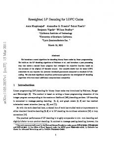
The TMS320C6416 is able, for example, to sum two pairs of 16 bits data in a single instruction (the same is true for the min operation). In order to take full advantage of SIMD instruction set, a different packing order was adopted in the de nition of both Lr and the auxiliary structure. As can be observed in g. 2, at each iterative cycle of both forward and backward/updating steps, two pairs of (Lrmn ; LQn ) values are processed (against one pair in 32-bit version). The computational complexity of the forward step remained unchanged, meaning that we were able to process the same number of data, twice as fast. In the backward/updating case, there was an increase to 9 CPU cycles, meaning that we were able to perform 1.3 times faster. Hard decoding is also accomplished two times faster. Obviously, this approach could be easily generalized to an 8 bit version.
1
Lr1
4.2 16-bit version
Compute: Lqnm = LQn – Lrmn Ai =Ai-1 Lqnm
Launch read of LQn
M
LQ structure
Lqa3
a2
LQN-1 LQN
In de
64-bit read
L
1
Lr1
LQi
Lqa2
Index LQa2
64-bit
sequential reading
CN1 [a1, a2, ... ak N(2) ; k’= #N(2) ]
a1
L
LQ2
ead
Lr1
LQ1
it r
CN2 [b1, b2, ... bk’
Weight CN1 Index LQa1
b 32-
N(1) ; k = #N(1) ]
Lr structure
of each value of the LQ structure. Sequential data access is taken using 64-bits reads. The process of verifying if all parity checks equations are satis ed is also optimized, by just stopping the testing procedure when a code restriction fail.
32-bit write
Compute: Bi = Bi+1 Lqnm Bi-1 = Bi Lq(n-1)m L’ rmn = Ai-1 Bi+1 L’ rm(n-1) = Ai-2 Bi LQ’ rmn n = Lqnm + L’ LQ’ rm(n-1) n-1 = Lq(n-1)m + L’
16-bit write 16-bit write
Backward/Updating Step
M
Figure 2:
Vectorized LDPC decoding using horizontal scheduling and the forward backward method. Data structures layout and processing ow for the 16 bit version.
5. EXPERIMENTAL RESULTS Decoding results were obtained using medium length LDPC codes, namely, two regular (504; 252) and (1908; 1696) codes, with CN's of weight, respectively, 6 and 36, and one irregular (1057; 813) with CN's of weight 17 and 18 [16].
14th European Signal Processing Conference (EUSIPCO 2006), Florence, Italy, September 4-8, 2006, copyright by EURASIP
The processing time required to perform the forward, backward/updating and hard decoding steps is independent of the channel SNR. The measured time to carry out the mentioned steps using hand optimized machine code is shown in table 1 in terms of the number of CPU cycles per iteration. In order to perform a fair comparison between the different codes, it is also presented the number of CPU cycles per iteration and per edge (a Tanner graph connection between a CN and a BN) which represents the computation burden of each (Lrmn ; LQn ) pair. By comparison of these results, we observe that independently of the code characteristics (length, rate, regularity and CN's weights), the obtained values are almost constants which shows the effectiveness of the proposed approaches. For the (504; 252) code the 16-bit version improvement is almost negligible due to the short weight of the CN's, which means a low pipelining programming gain. Additionally, we can conclude by comparison with the 32-bit register version (auxiliary data structure stored in the CPU registers) that the proposed generic decoding structure performs almost as fast as the dedicated solution. For the (1057; 813) and (1908; 1696) codes, we can recognize a signi cantly decrease in the number of CPU cycles per iteration in the 16-bit (SIMD) version case, i.e., a gain of approximately, 1:3 and 1:4, respectively. For heavy CN codes the gain is almost constant. However, for odd weight CN's codes, it may occur a little gain loss, since the execution of the prolog and epilog of both forward and backward/updating steps is more complex (see in g. 2 the odd weight CN case where the last pair (Lrmn ; LQn ) must be processed alone). Number of code edges CPU cycles 32-bit / Iteration 16-bit Reg. CPU cycles 32-bit /Iteration/Edge 16-bit
(504,252) (1057,813) (1908,1696) 1 512 4 228 7 632 22 698 68 607 125 426 21 147 53 041 91 988 18 009 15.01 16.23 16.43 13.99 12.55 12.05
Table 1: Full decoding (except syndrome computation) processing time in CPU cycles per iteration for 32-bit, 16-bit and register versions.
Considering a maximum number of 10 iterations, it is shown in Table 2 the average number of CPU cycles per iteration to perform the whole proposed algorithm (vectorized min-sum with horizontal scheduling) for the 32-bit version. 2dB 3dB 4dB
(504,252) 25786 28664 30771
(1057,813) 69314 74553 88192
(1908,1696) 126824 126906 139182
Table 2: The average processing time in CPU cycles per iteration for the 32-bit version. De nitely, there is a signi cantly increase in the number of CPU cycles per iteration for high SNR's. It means that the developed process to verify the syndrome vector works well. For small SNR values, there is a high probability to nd an early failed syndrome equation, which means that (^ c HT = 0) veri cation will be stopped almost at the beginning. In opposition, for high SNR values, (^ c HT = 0) veri cation takes
an important portion of the overall decoding time. 6. CONCLUSION In this work, we have proposed ef cient vectorized LDPC decoding solutions (16 and 32 bits) based on the serial check node processing (horizontal scheduling) and the min-sum algorithm. The target device was a modern xed point SIMD DSP. Also, an improved forward-backward method was developed. The obtained experimental results have shown the applicability of the proposed approaches in real time decoding of medium length LDPC codes included in high bit rate transmission/storage data systems. REFERENCES [1]
R. G. Gallager, “Low-Density Parity-Check Codes”, IRE Transactions on Information Theory, vol. IT-8, pp.21-28, Jan. 1962.
[2]
R. G. Gallager, Low-Density Parity-Check Codes, Cambridge, MIT Press, 1963.
[3]
D. J. C. MacKay and R. M. Neal, “Near Shannon Limit Performance of Low Density Parity Check Codes”, IEEE Electronics Letters, vol. 32, no. 18, pp. 1645-1646, Aug. 1996.
[4]
ETSI EN 302 307 V1.1.1, Digital Video Broadcasting (DVB); Second generation framing structure, channel coding and modulation systems for Broadcasting, Interactive Services, News Gathering and other broadband satellite applications, March 2005.
[5]
Tom Richardson, “The Renaissance of Gallager's Low Density Parity Check Codes”, IEEE Commun. Magazine, vol. 41, no. 8, pp. 126131, Aug. 2003.
[6]
R. Tanner, “A Recursive Approach to Low Complexity Codes”, IEEE Trans. Inform. Theory, vol. 27, no.5, pp. 533-547, Sept. 1981.
[7]
T. Richardson and R. Urbanke, “The Capacity of Low-Density ParityCheck Codes Under Message-Passing Decoding”, IEEE Transactions on Information Theory, vol. 47, no. 2, pp. 599-618, Feb. 2001.
[8]
J. Chen and M. Fossorier, “Near Optimum Universal Belief Propagation Based Decoding of Low-Density Parity Check Codes”, IEEE Transactions on Communications, vol. 50, no. 3, pp. 406-414, March 2002.
[9]
J. Zhang and M. Fossorier, “Shuf ed Belief Propagation Decoding”, Thirty-Sixth Asilomar Conference on Signals, Systems and Computers 2002, vol. 1, pp. 8-15, Nov. 2002.
[10]
E. Sharon, S. Litsyn and J. Goldberger, “An ef cient message-passing schedule for LDPC decoding”, 23rd IEEE Convention of Electrical and Electronics Engineers in Israel, pp. 223-226, Sep. 2004.
[11]
H. Xiao and A. M. Banihashemi, “Graph-Based Message Passing Schedules for Decoding LDPC Codes”, IEEE Transactions on Communications, vol. 52, no. 12, pp. 2098-2105, Dec. 2004.
[12]
F. Zarkeshvari and A. H. Banihashemi, “On implementation of MinSum Algorithm for Decoding Low Density Parity Check (LDPC) Codes”, IEEE Globecom 2002, vol. 2, pp.1349-1353, Nov. 2002.
[13] [14]
TMS320C6000 CPU and Instr. Set Ref. Guide, Texas Inst., Oct. 2000.
[15]
X.-Y. Hu, E. Eleftheriou, D.-M. Arnold and A. Dholakia, “Ef cient Implementations of the Sum-Product Algorithm for Decoding LDPC Codes”, IEEE GLOBECOM '01, vol. 2, pp. 1036-1036E, Nov. 2001.
[16]
http://www.inference.phy.cam.ac.uk/mackay/codes
F. R. Kschischang, B. J. Frey and H. Loeliger, “Factor Graphs and the Sum-Product Algorithm”, IEEE Transactions on Information Theory, vol. 47, no. 2, pp. 498-519, Feb. 2001.