A Repository Of Sensor Data For Autonomous Driving Research. Michael Shneier, Tommy Chang, Tsai Hong, Gerry Cheok, Harry Scott, Steve Legowik, Alan ...
Proceedings of the SPIE Aerosense Conference, Orlando, FL, April 21 - 25, 2003.
A Repository Of Sensor Data For Autonomous Driving Research Michael Shneier, Tommy Chang, Tsai Hong, Gerry Cheok, Harry Scott, Steve Legowik, Alan Lytle National Institute of Standards and Technology 100 Bureau Drive, Stop 8230 Gaithersburg, MD 20899 ABSTRACT 1 We describe a project to collect and disseminate sensor data for autonomous mobility research. Our goals are to provide data of known accuracy and precision to researchers and developers to enable algorithms to be developed using realistically difficult sensory data. This enables quantitative comparisons of algorithms by running them on the same data, allows groups that lack equipment to participate in mobility research, and speeds technology transfer by providing industry with metrics for comparing algorithm performance. Data are collected using the NIST High Mobility Multi-purpose Wheeled Vehicle (HMMWV), an instrumented vehicle that can be driven manually or autonomously both on roads and off. The vehicle can mount multiple sensors and provides highly accurate position and orientation information as data are collected. The sensors on the HMMWV include an imaging ladar, a color camera, color stereo, and inertial navigation (INS) and Global Positioning System (GPS). Also available are a highresolution scanning ladar, a line-scan ladar, and a multicamera panoramic sensor. The sensors are characterized by collecting data from calibrated courses containing known objects. For some of the data, ground truth will be collected from site surveys. Access to the data is through a web-based query interface. Additional information stored with the sensor data includes navigation and timing data, sensor to vehicle coordinate transformations for each sensor, and sensor calibration information. Several sets of data have already been collected and the web query interface has been developed. Data collection is an ongoing process, and where appropriate, NIST will work with other groups to collect data for specific applications using third-party sensors. Keywords: data collection, registration, calibration, ladar, images, position and orientation, robot vehicle, on-road, off-road
INTRODUCTION
As part of the Army’s Demo III program1, NIST has instrumented a military HMMWV to enable it to drive autonomously and to carry an array of sensors for characterizing the terrain around the vehicle. This vehicle is being used to collect sets of data that are tied together through accurate position and time information collected with the sensory data. Data are collected for specific applications, such as off-road driving, on-road driving, and indoor driving. Substantial effort has been spent on data collection of rugged environments for the purpose of characterizing the difficulty of the terrain. There are two major goals of the project. First, the sensory data are used to develop algorithms that enable the vehicle to navigate through both off-road and onroad terrain. Second, the data are used to devise methods of characterizing terrain in terms of roughness, density of vegetation, spacing of obstacles, etc. More generally, the data are being collected and made available to researchers in order to increase the pace of research in sensor processing for autonomous vehicles. The project will provide data of known accuracy and precision to researchers and developers, enable algorithms to be developed using realistically difficult sensory data, make it possible to compare algorithms quantitatively by running them on the same data, and enable groups that lack equipment to participate in autonomous vehicle research. We hope that it will also speed technology transfer by providing industry with metrics for comparing algorithm performance, and help with sensor development by finding weaknesses in current sensors. In addition to the HMMWV, NIST has three other platforms useful for collecting data for mobile robots. One is a General Dynamics Experimental Unmanned Vehicle (XUV)*. The second is a Chrysler sedan equipped with an INS/GPS system and various sensors. The third is an indoor robot with no inertial navigation,
Color Camera
Riegl Ladar
Sensors include a General Dynamics Robotics Systems (GDRS)* imaging ladar (Table 1) mounted on a tilt platform, a color camera mounted on top of the ladar on the tilt platform, and a highly accurate positioning system (Table 2 and Table 3)3.
GPS Imaging Ladar
Color Stereo
Other sensors that are commonly used on the vehicle include a pair of color stereo cameras, a Sick line-scan ladar, currently mounted on the back of the vehicle, and a Riegl high-resolution scanning ladar (Table 4).
3. SENSOR CALIBRATION AND REGISTRATION
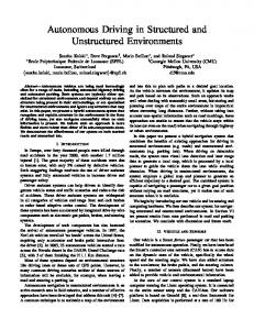
Figure 1 A view of the NIST HMMWV showing some of the sensors.
but with a color camera and a line-scan ladar. NIST also built and maintains a series of instrumented reference test arenas intended for evaluating the performance of robots used for urban search and rescue2. This paper will focus on the NIST HMMWV. It will describe the procedures used for collecting data, the types of data that are available, and the associated information that can be supplied with the data. A webbased interface has been developed that enables queries to be made in terms of keywords, sensors, locations, dates, etc. More advanced search capabilities are being developed that will enable content-based searches.
2. THE NIST HMMWV The NIST HMMWV is a military vehicle modified for the purposes of research and development in mobile robotics. The vehicle has the capability of driving autonomously or of being driven by a human driver. The vehicle is driven manually during data collection. Mounted on the vehicle are racks to hold computers and related equipment, a power generator, and numerous sensors (Figure 1). The sensor mounts are flexible, so that new sensors can easily be added.
This work aims to provide sets of data that are registered in both space and time. Registration enables information from multiple sensors to be integrated and enables the spatial relationships between successive samples to be computed. Preparing for data collection includes calibrating the sensors and accurately measuring their positions and orientations on the vehicle. Then data are collected from calibrated courses containing known objects to enable the capabilities of each sensor to be quantified. The cameras are calibrated using Bouguet’s method4. The ladars are each calibrated using special-purpose methods. For example, the GDRS ladar is calibrated by mounting it on a highly accurate pan-tilt platform. The pointing direction of each laser pixel is determined by moving the ladar until the laser beam for that pixel is centered on a calibration target. The angle at which the laser is pointed for each pixel can then be determined from the pan and tilt position of the platform. The positions and orientations of the sensors relative to the vehicle coordinate system and to each other are determined using an external measurement system. We use an ArcSecond laser-based site measurement system (SMS) to provide these measurements. For the Riegl ladar, the approach is to park the vehicle in such a way that it faces two orthogonal walls. The Riegl is then used to scan these walls and the ground Figure 2), and a transformation is obtained from the building to the Riegl coordinates. The ArcSecond sensor is then used to determine the HMMWV to ArcSecond transform
*
Certain commercial equipment, instruments, or materials are identified in this paper in order to adequately specify the experimental procedure. Such identification does not imply recommendation or endorsement by NIST, nor does it imply that the materials or equipment identified are necessarily best for the purpose.
vehicle pose and the time are provided by an Applanix navigation unit that combines an inertial component with information from the Global Positioning System (GPS). This unit typically provides real-time data accurate to better than one meter and a few hundredths of a degree. With post-processing, the accuracy is a few centimeters in distance and angular accuracy is a few thousandths of a degree (Table 2 and Table 3).
Figure 2 Data from a scan of orthogonal walls using the Riegl ladar.
and the wall to ArcSecond transform. Finally, the Riegl to HMMWV transform can be obtained by matrix multiplication: Riegl to HMMWV = Riegl to Building * Building to ArcSecond * ArcSecond to HMMWV. Similar methods are used to locate the other sensors relative to the vehicle.
4. COLLECTING DATA Data are collected in two primary modes. One is while the vehicle is driving normally, while the other is with the vehicle stationary. Some of the sensors do not run in real time, so can only be used when the vehicle is not moving. The trade-off between the two modes is that while data acquired in real-time approximate more closely the actual driving conditions, they are less accurate and usually of lower resolution than data from the slower sensors used when the vehicle is stopped. The expectation is that this higher resolution data will soon become available in real time as new sensors are developed. A critical part of data collection for mobile vehicle applications is to record the vehicle position and orientation (pose) and the time at which each data sample is acquired. This enables data collected from multiple sensors to be registered, and also allows the data for a complete mission to be compiled into a reconstruction of all the terrain that was traversed. The
To date, data have been collected for two main purposes. The first is to provide a large variety of input data for developing and testing sensory processing algorithms. More recently, a new application has required characterizing terrain and developing measures of difficulty of traversal for robotic vehicles. This has led to a more structured way of collecting data, and is the main reason for needing highly accurate pose and time information and for using high-resolution sensors such as the Riegl ladar (Table 4). Collecting data for algorithm development involves driving the vehicle in the way it would normally operate, over terrain representative of the environment in which the vehicle normally operates. The data are acquired as follows. First, the sensors are calibrated and registered, and the navigation system is initialized. Next, a human driver drives the vehicle over the terrain of interest, and the sensors collect all the real-time sensory data simultaneously. The sensors are started simultaneously, and navigation and timing data are collected with the sensory data. Typically, the collection is divided into segments about three minutes in length, mainly for convenience in later processing and storage. Longer periods can also be collected, limited only by the available storage space, which is large. When data are collected for terrain characterization, the process is more methodical. Data have usually been collected on courses laid out for evaluating the capabilities of the Demo III vehicle, the XUV. These courses are defined by a set of GPS waypoints, through which the XUV is supposed to pass as it carries out its mission. Data are collected both for the entire course and for locations that required an emergency stop for the XUV or where the vehicle displayed “interesting” behavior, such as backing up, suddenly changing direction, or performing an unanticipated intelligent maneuver. Three sets of data are collected for each course. First, the vehicle is driven over the course collecting data with the real-time sensors. Next, the vehicle is moved
Figure 5 Example scene from an off-road data set Figure 3 Web interface for querying sets of data. to the first waypoint on the course. Starting from this point, and moving a fixed distance between samples, scans are taken of the terrain using the Riegl ladar and a set of six cameras arranged in a ring around the Riegl. The scans are not taken at the highest resolution the sensor can measure, but still provide much more accurate information than the real-time sensors. The navigation data are also stored to provide the position and heading of the data collection vehicle at the time the sample is collected. The entire course is sampled in
Figure 4 Partial results of query.
this way. Finally, a set of high-resolution scans is taken of the difficult or interesting locations on the course. 5.
DATA STORAGE AND ACCESS
Information about each set of data is stored in a relational database, and the data sets themselves are stored in a large capacity storage repository. Each set of data is described in terms of the location, time of year, time of day, weather, sensors used in the collection, and keywords describing the data. A web query interface is used to select data from the repository (Figure 3 and Figure 4). This interface will shortly be made available outside the NIST firewall, and researchers are encouraged to take advantage of the data. A wide range of off-road data has been collected, including desert, woods, grassy areas, bushes, water, tree lines, obstacles (rocks, trees, ditches, etc.) and undulations and slopes of various sorts (Figure 5). Onroad data includes dirt and gravel roads as well as paved roads, road markings, road signs, and features along the sides of the road (Figure 6). Some of the data includes pedestrians, other vehicles, and special situations such as roadwork, human gestures for guiding the vehicle, and images of a calibration target. In the near future, ground truth data will be acquired for some of the data from an aerial survey of the NIST grounds and surrounding area at a resolution of about 0.3 meters per point. The ground truth will include features such as roads, road signs and markings, telephone poles, buildings, trees, fences, ponds, etc. This data will provide both a way of evaluating the sensory data and a resource for testing recognition
metrics for comparing algorithm performance will also enhance technology transfer. The project will also help with sensor development by identifying weaknesses in current sensors. Acknowledgements We are grateful for the support of the Army Research Laboratory and the Defense Advanced Research Projects Agency MARS program. REFERENCES Figure 6 Sample image from an on-road data set.
algorithms and using a priori information in sensory processing. Other information available with the data includes the relative positions and orientations of the sensors, their calibration parameters, the time at which each sample was collected, and the position and orientation of the vehicle at that time. This makes it easy to register the sensors with each other and with the location of the vehicle in the world.
6. CONCLUSIONS By making data of known accuracy and precision available to researchers who lack the equipment and resources to collect it, NIST hopes that algorithm development will be spurred. Quantitative comparison of algorithms will be made easier because the data is of known accuracy and precision. Providing industry with
1. Shoemaker, C. M. and Bornstein, J. A., "The Demo3 UGV Program: A Testbed for Autonomous Navigation Research," Proceedings of the IEEE International Symposium on Intelligent Control, Gaithersburg, MD 2. Jacoff, A., Messina, E., and Evans, J., "Experiences in Deploying Test Arenas for Autonomous Mobile Robots," Proceedings of the 2001 Performance Metrics for Intelligent Systems (PerMIS) Workshop, in association with IEEE CCA and ISIC, Mexico City, Mexico, 2001. 3. Scott, H. and Szabo, S., "Evaluating the Performance of a Vehicle Pose Measurement System," Proceedings of the Performance Metrics for Intelligent Systems (PerMIS) Workshop, Gaithersburg, MD, 2002. 4. Bouguet, J-Y., Camera Calibration Toolbox for Matlab, http://www.vision.caltech.edu/bouguetj/calib_do c/, Oct.,2002.
Property 8 laser beams, 1 rotating mirror Scan resolution Scan coverage Angular resolution Maximum frame rate Range Range resolution/accuracy Data measurement rate Day/Night Operation
Specification With 8 facets 32 lines × 180 pixels 20° × 90° 0.658° × 0.5° 60 scans/s but 30 scans/s in practice 5 m to 70m (vertical surface) ±7.6 cm / 15 cm Range: 345,600 measurements/s. Range Independent of ambient light
Table 1 GDRS Area-Scan Ladar Specifications. POS LV 420-RT (Using DGPS) X, Y Position (m) Z Vertical Position (m) Roll & Pitch (deg) True Heading (deg)
0 min. 1.0 1.5-2.0 0.02 0.02
1 min. 1.5 2.0 0.02 0.02
GPS Outage Duration (minutes) 3 min. 5 min. 10 min. 1.75 2.0 2.5 2.0 2.0 2.5 0.02 0.02 0.02 0.04 0.06 0.10
20 min. 3.5 3.0 0.02 0.20
Table 2 Real-Time Performance of Applanix POS LV 420 Intertial Navigation Unit. POS LV 420 (Post processed) X, Y Position (m) Z Vertical Position (m) Roll & Pitch (deg) True Heading (deg)
0 min. 0.02 0.03 0.005 0.02
1 min. 0.12 0.15 0.005 0.02
GPS Outage Duration (minutes) 3 min. 5 min. 10 min. 0.40 0.75 1.5 0.50 0.65 1.0 0.005 0.007 0.007 0.02 0.03 0.035
Table 3 Performance of Applanix LV 420 with post-processing. Property Scan coverage Angular stepwidth Angular resolution Frame scan rate Minimum Range Maximum Range Range resolution
Specification 80° x 330° 0.072° to 0.36° 0.036° 1°/s to 15°/s 2m 350 m (25 mm resolution, natural target) 25 mm or 50 mm, selectable
Table 4 Manufacturer’s Specifications - Riegl LMS Z210 Ladar.
20 min. 2.5 2.0 0.09 0.035