A Review on Automated Brain Tumor Detection and Segmentation from MRI of Brain 1
2
3
4
Sudipta Roy , Sanjay Nag , Indra Kanta Maitra , Prof. Samir Kumar Bandyopadhyay 1
Department of Computer Science and Engineering, University of Calcutta, 92 A.P.C. Road, Kolkata-700009, India. 3 Research Scholar, Department of Computer Science & Engineering, University of Calcutta, India. 2 Research Fellow, Department of Computer Science & Engineering, University of Calcutta, India. 4 Vice Chancellor, West Bengal University of Technology Kolkata, West Bengal, India.
[email protected],
[email protected],
[email protected],
[email protected]
ABSTRACT: Tumor segmentation from magnetic resonance imaging (MRI) data is an important but time consuming manual task performed by medical experts. Automating this process is a challenging task because of the high diversity in the appearance of tumor tissues among different patients and in many cases similarity with the normal tissues. MRI is an advanced medical imaging technique providing rich information about the human soft-tissue anatomy. There are different brain tumor detection and segmentation methods to detect and segment a brain tumor from MRI images. These detection and segmentation approaches are reviewed with an importance placed on enlightening the advantages and drawbacks of these methods for brain tumor detection and segmentation. The use of MRI image detection and segmentation in different procedures are also described. Here a brief review of different segmentation for detection of brain tumor from MRI of brain has been discussed.
KEYWORDS: MRI of Brain, Tumor Segmentation, Tumor Detection, Automated System, Pre-processing, Filtering. 1. INTRODUCTION: Magnetic resonance imaging of brain image computing has very increased field of medicine by providing some different methods to extract and visualize information from medical data, acquired using various acquisition modalities. Brain tumor segmentation is a significant process to extract information from complex MRI of brain images. Diagnostic imaging is a very useful tool in medical today. Magnetic resonance imaging (MRI), computed tomography (CT), digital mammography, and other imaging processes give an efficient means for detecting different type of diseases. The automated detection methodology have deeply improved knowledge of normal and diseased examination for medical research and are a important part in diagnosis and treatment planning when the number of patients increases[1]. Segmentation has spacious application in medical imaging field such as MRI of brain, MRI of human knee, etc. for analyzing MRI of brain, anatomical structures such as bones, muscles blood vessels, tissue types, pathological regions such as cancer, multiple sclerosis lesions and for dividing an entire image into sub regions such as the white matter (WM), gray matter (GM) and cerebrospinal fluid (CSF) spaces of the brain automated delineation of different image components are used. Thus in the field of MRI of brain tumor segmentation from brain image is significant as MRI is particularly suitable for brain studies because of its excellent contrast of soft issues, non invasive characteristic and a high spatial resolution. Brain tumor segmentation partitions a portion into mutually special and pooped regions such that each region of interest is spatially contiguous and the pixels within the region are homogeneous with respect to a predefined criterion. Mostly, homogeneity conditions include values of concentration, texture, color, range, surface normal and surface curvatures. Through past many researchers have prepared important research in the field of brain tumor segmentation but still now it is very important research fields. Medical history, biopsy–whereby a small amount of brain tissue is excised and analyzed under the microscope–and imaging studies are all important to reach a diagnosis of brain tumor. Standard x-rays and computed tomography (CT) can initially be used in the diagnostic process. However, MRI is generally more useful because it provides more detailed information about tumor type, position and size. For this reason, MRI is the imaging study of choice for the diagnostic work up and, thereafter, for surgery and monitoring treatment outcomes [2]. Thus here short introduction with MRI, brain tumor and automated system also discussed. Rest of the part organized as follows: Section 2 describes the Magnetic resonance imaging of Brain Image. In Section 3 there is a description about Brain Tumor. Section 4 describes the automated system and Section 5 consists of Preprocessing. Colour Fundamentals is described in Section 6 and Section 7 consists of Segmentation. In Section 8 there are Summery and Conclusion. Section 9 consists of Reference.
1
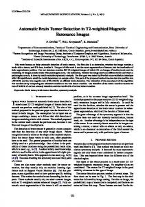
2. Magnetic resonance imaging (MRI) : A magnetic resonance imaging instrument or MRI Scanner [3] uses powerful magnets to polarize and excite hydrogen nuclei i.e. proton in water molecules in human tissue, producing a detectable signal which is spatially encoded, resulting in images of the body [4]. MRI mainly uses three electromagnetic fields they are : i) A very strong static magnetic field to polarize the hydrogen nuclei, named as the static field, ii) A weaker time varying field(s) for spatial encoding, named as the gradient field, iii) A weak radio frequency field for manipulation of hydrogen nuclei to produce measurable signals collected through RF antenna. The variable behaviour of protons within different tissues leads to differences in tissue appearance. The different positioning of MRI of brain with T1 and T2 weight is shown below.
(a)
(b)
(c)
(d)
(e)
(f)
Figure 1 : MRI of brain cited by http://www.mr-tip.com/serv1.php?type=isimg. T2 weighted MR image (a) brain shows cortex, lateral ventricle, and falx cerebri, (b) brain shows eyeballs with optic nerve, medulla, vermis, and temporal lobes with hippocampal regions, (c) head shows maxillary sinus, nasal septum, clivus, inner ear, medulla, and cerebellum. T1 weighted MR image (d) brain shows cortex, white and grey matter, third and lateral venticles, putamen, frontal sinus and superior sagittal sinus, (e) brain shows eyeballs with optic nerve, medulla, vermis, and temporal lobes with hippocampal regions,(f) brain shows cortex with white and grey matter, corpus callosum, lateral ventricle, thalamus, pons and cerebellum from the same patients
3. Brain Tumor: A brain tumor is a mass of cells that have grown and multiplied uncontrollable i.e. a brain tumor is an uncontrolled growth of solid mass formed by undesired cells either normally found in the different part of the brain such as glial cells, neurons, lymphatic tissue, blood vessels, pituitary and pineal gland, skull, or spread from cancers mainly located in other organs [5]. Brain tumors are classified based on the type of tissue involved in the brain, the positioning of the tumor in the brain, whether it is benign tumor or malignant tumor and other different considerations. Brains tumors are the solid portion permeate the surrounding tissues or distort the surrounding structures [6]. There are different type of brain tumor they are i) Gliomas, ii) Medulloblastoma, iii) Lymphoma, iv) Meningioma, v) Craniopharyngioma, vi) Pituitary adenoma.
(a) (b) (c) (d) (e) Figure 2: A set of brain tumor images from MRI of brain output cited by Herbert H. Engelhard et al.(2003)[7]. a) Axial T1-weighted with tumor, b) T2-weighted with central positioning tumor, c) Contrast enhanced T1-weighted image showing ring formed tumor, d) Contrast enhanced T1weighted image with high grade oligodendro glioma e) T2-weighted image with high grade oligodendro glioma from the same patient.
4. Automated System: Automated system (detection) of brain tumor through MRI is basically called Computer-Aided Diagnosis (CAD) system. The CAD system can provide highly accurate reconstruction of the original image i.e. the valuable outlook and accuracy of earlier brain tumor detection. It consists of two or more stage. In the initial stage pre-processing has required after that stages post-processing i.e. segmentation are required. Then detection strategies and other information, feature extraction, feature selection, classification, and performance analysis are compared and studied. Pre-processing techniques are used to improvement of image quality and remove small artefacts and noise for the accurate detection of the undesired regions in MRI. Post-processing is used to segment with different strategy the brain tumor from the MRI of brain images. In this review, here focus on the appearance of tumors in MRI images, the grade of tumors and some general information which will be useful in the detection, segmentation and interpretation of brain tumors from MRI images. An automated brain tumor detection procedure follows some steps which is shown diagram below.
2
MRI of Brain Images Pre-Processing Post-Processing: Segmentation Feature Extraction
Image Analysis Diagnosis
Figure 3: Brain tumor detection steps
5. PREPROCESSING: Pre-processing mainly involves those operations that are normally necessarily prior to the main goal analysis and extraction of the desired information and normally geometric corrections of the original actual image. These improvements include correcting the data for irregularities and unwanted atmospheric noise, removal of non-brain element image and converting the data so they correctly reflected in the original image. Segmentation is the process of partitioning an image to several segments but the main difficulties in segmenting an images are i) Noise, ii) Blur Low Contrast, iii) The bias field (the occurrence of smoothly varying intensities within tissues) , iv) The partial-volume effect (a voxel contributes in multiple tissue types) . Image filtering and enhancement stage is the most obvious part of medical image processing. This pre-processing stage is used for reducing image noise, highlighting important portions, or displaying obvious portions of digital images [8]. Some more techniques can employ medical image processing of coherent echo signals prior to image generation and some of the images are hanging from clip hence they may produce noise. The enhancement stage includes resolution enhancement; contrast enhancement. These are used to suppress noise and imaging of spectral parameters. After this stage the medical image is converted into standard image without noise, film artefacts and labels. 5.1 Existing de-noising methods: In spite of the presence of substantial number of state of the art methods of de-noising but accurate removal of noise from MRI image is a challenge. Methods such as use of standard filters to more advanced filters, nonlinear filtering methods, anisotropic nonlinear diffusion filtering, a Markov random field (MRF) models, wavelet models, non-local means models (NL-means) and analytically correction schemes. These methods are almost same in terms of computation cost, de-noising, quality of de-noising and boundary preserving. So, de-noising is still an open issue and de-noising methods needs improvement. Linear filters reduce noise by updating pixel value by weighted average of neighbourhood but degrade the image quality substantially. On the other hand, non linear filters preserve edges but degrade fine structures. i) Non-local (NL): This method exploits the redundant information in images [9]. The pixel values are replacement by taking weighted average of locality similar to the neighbourhood surrounding of the image. MRI images, consists of non-repeated details due to noise, complex structures, smear in acquisition and the partial volume effect originating from the low sensor resolution that is abolished by this type of method. ii) Analytical correction method: This method attempts to estimate which is noise and which is noise-free signal from observed image. This method uses maximum likelihood estimation i.e. depending upon the signal [10] to estimate noise and noise free portion of images. Neighbourhood smoothing is used to estimate noise free image by considering signal in small region to be constant. Edges in the image are degraded. iii) A Markov random field method (MRF): In this method spatial correlation information is used to preserve fine detail [11], i.e., spatial regularization of the noise estimation is performed. In MRF method, the updating of pixel value is done by iterated conditional modes and simulated annealing with maximizing a posterior estimate. iv) Wavelet based methods: In frequency domain these method is used for de noising and preserving the actual signal. Application of wavelet based methods on MRI images makes the wavelet and scaling coefficients biased. This problem is solved by squaring the MRI image by non central chi-square distribution method [12]. These make the scaling coefficients independent of the signal and thus can be easily removed [13]. In case of low SNR images, finer details are not preserved [14]. These are the major techniques used in filtering image and to enhance the image quality use filtering with some other procedure which is describe in the next section.
3
5.2 Images Enhancement and Filtering: Image enhancement is the improvement of digital image quality without any knowledge about the original source image degradation. The enhancement methods mainly divide into two methods, direct and indirect methods. In direct method is to show the contrast of the image and then enhance the contract but in the indirect method contrast of the image is not essential. Under-enhanced when some regions of the image may be over-enhanced are the great disadvantage of the contrast enhancement methods. Mainly image enhancements are the intensity and contrast manipulation, noise reduction, undesirable background removal, edges Sharpening, filtering etc. Image enhancement methods improve the visual appearance of images from MRI and the contrast enhancing brain volumes were linearly associated. The enhancement activities are removal of film artefacts and labels, filtering the images. Median Filter, Low pass Filter, Gradient Based Method, Prewitt edge-finding filter, Nonlinear Filter, V-filter, and other filter with contrast Enhanced filter are shortly describe below. There are several filtering technology’s which can improve the MRI image quality but there are several advantage and disadvantage which describe very shortly individually. 5.2.1 Median Filter: Median Filter remove the noise with high frequency components from MRI without disturbing the edges and it is used to reduce’ salt and pepper’ noise. This technique calculates the median values i.e. set median value pixels values of the surrounding pixels to determine the new de-noised value of the pixel [15]. A median is calculated by sorting all pixel values by their size, then selecting the median value as the new value for the pixel. The basic function for median image is written below in equation (1), where f(x,y) output median and g(x,y) is the original values. median f (x, y) g ( i , j ) (i , j ) N
Before filtering if the intensity values are 46, 58, 47, 49, 41, 45, 42, 55, and 59. So the ascending orders of the pixel intensity values are 41, 42, 45, 46, 47, 49, 55, 58, and 59. So the median value is 47 and this 47 replace the value 41 in the actual output of the median filter. 46
58
47
46
58
47
49
41
45
49
47
45
55
59
42
55
59
42
(a)
(b)
Figure 4: Median Filter a) Shows pixel intensity value before filtering and b) Shows pixel intensity value after filtering.
Different type of median filter are shortly describe below i) Min-Max Median Filter: It is conditional nonlinear filter with (3x3) window is use for scanning the image left to right and top to bottom. In this methods center pixel of window (2, 2) is considered as a test pixel and center pixel value is replaced by the median value of the neighbour pixel which pixel is less than the minimum value and greater than the maximum value [16]. Then center pixel is considered as corrupted pixel that is why value is replaced by median value of pixels nearby in window otherwise pixel is treated as non corrupted pixel and kept pixel value remain unchanged. ii) Center Weighted Median Filter: It is an extension with weighted median filter in which it produce more weight to the center. It is very much effective to smooth the image with capability of image enhancement [17]. In this procedure center pixel of (2n+1) square window measured as test pixel and if center pixel (n+1,n+1) less than minimum value present in rest of pixel in window and greater than maximum value present in rest of pixel in window then center pixel is treated as corrupted pixel. iii) Adaptive Median Filter: It is conditional non-linear filter with two conditions that are used to detect corrupted pixels and to verify correctness of median value, and also uses increasing shifting windows size until correct value of median is calculated and corrected median value replace the corrupted pixel to reduce noise [18]. If the median value or test pixel is within minimum and maximum limit then it is corrected pixel otherwise treated as corrupted pixel and then increase the window size until correct median value within the limit is produce, then the corrupted value is replaced by median value. iv) Progressive Switching Median Filter: It is [19] is conducted by two step process in which first step is noise pixel identification with fixed size window size. If the test pixel is not within maximum or minimum value present rest of the pixel then this pixel is treated as corrupted pixel and in the second step these corrupted pixel are replaced by the median value intensity. Median value out of maximum/minimum limit is treated as corrupted median values which are not used and then window size increases. Here median value is calculated same as in adaptive median filter without considering the corrupted pixel present in window. As low frequency image is generated and the images are enhanced using median filter, suppresses isolated noise without blurring sharp edges. From figure 5 we see that median filter produce very good results and the median is much less sensitive than 4
the mean to extreme values thus median filtering is therefore better able to remove this outlier without reducing the sharpness of the image. 5.2.2 Mean Filter: In case of mean or average filter replace the center of the pixel by mean (average) value of the pixels. Thus if a square window of size 2k+1 is used, where k within 1 to n, odd width and height are taking and average value is replaced by (k+1, k+1) position [20,21,24,25]. The basic function for median is written below in equation (2), where f(x,y) output mean and g(x,y) is the original values.
1 f ( x, y ) K
K
g ( x, y ) i
i 1
Each time of scan value of central pixel of window is replaced by the average value of its neighbouring pixels comes within the window. If k=1 the window size is 3×3 and center position is 2×2 is shown in figure 5 Before filtering if the intensity value are 46, 58, 47,49, 41, 45, 42, 55, 58 . So the average value is 49 and then 41 are replaced by 49. 46
58
47
46
58
47
49
41
45
49
49
45
55
58
42
55
58
42
(a)
(b)
Figure 5 : Mean filter: a) Shows pixel intensity value before filtering and b) Shows pixel intensity value after filtering.
(a)
(b)
(c)
(d)
(e) (f) (g) (h) Figure 6 : A set of MRI of brain with different filtering output for the same image Output cited by Manohar Annappa Koli (2012) [20] a) original MRI image, b) original MRI with 50% noise, c) median filter, d) Min-Max Median Filter, e) Center Weighted Median Filter, f) Adaptive Median Filter, g) Progressive Switching Median Filter, h) Average Filter.
5.2.3 Low pass Filter: A low pass filter passage[23,24,25] only low value i.e. low intensity value of the pixel.Compute the 2D discrete Fourier transform of the image then apply an image operator to the transformed image and computer the inverse 2D discrete Fourier transform of the result of the image operator. Low-pass filtering zeroes out the frequency components above intensity, if f(x,y) is a function, for example the brightness in an image, its Fourier transform is given by threshold. It suppresses all frequencies higher than the cut-off frequency and leaves smaller frequencies unchanged. This is written below in equation (3).
H(u,v) =
{
D(u,v)
D(u, v ) D0
0
D(u, v ) D0
D (u , v) [(u M / 2)2 (v N / 2) 2 ]1/ 2
Take care of narrow noisy variations from MR images.
5
5.2.4 High-pass Filter [24, 25, 26]: working activities of this filter is some other than it passes high frequency and remain unchanged and block low frequency signal, the elements of the mask contain both positive and negative weights. H(u,v) =
{
0
D(u, v ) D0
D(u,v)
D(u, v ) D0
D (u , v) [(u M / 2)2 (v N / 2) 2 ]1/ 2
That is high-pass filter = original – low-pass. High-pass filter take care of undesirable small noise intensity and Useful for emphasizing transitions in intensity (e.g., edges) and Compute intensity differences in local image regions. 5.2.5 Gaussian Filter: The Gaussian smoothing [24,25,26] operator for the two dimensional image convolution operators that is used to `blur' images and remove detail and noise. It is produce output similar to the mean filter but some difference are written below. The Gaussian distribution in 2-D has the form is written below in equation (5), where is the standard deviation of the distribution.
Gaussian is random occurrence of white intensity value and its intensity value is drawn from Gaussian distribution, thus it is very much use to reduce Gaussian noise and as it linear filter so it is computationally efficient and enhances image quality with the image boundaries. 6. Colour Fundamentals: Colour models or colour spaces, indicate the colours in a benchmark way by using a coordinate system and a subspace in which each colour is represented by a single point of the coordinate system. The largely common colour spaces used in image processing [24, 25] methods are Gray, Binary form, RGB, HSV, HIS etc. Gray form are used in all binarized method, i.e. most of the segmentation technique used binarization methods original MR Brain image is a gray-level image may be inadequate to maintain fine description then pseudo colour conversion are need. Each gray value maps to an RGB item. To obtain more useful features and enhance the visual density, some of the method may applies pseudo-colour transformation, a mapping function that maps a gray-level pixel to a colour level pixel by a lookup table in a predefined colour map. An RGB colour map contains R, G, and B values for each item. But most of the segmentation applied on the gray image the RGB to gray conversion is needed. This colour conversion coordinate is shown in figure below.
Green (0,255,0) Yellow (255,255,0)
Cyan (0,255,255)
White (255,255,255)
Black (0,0,0)
Blue (0,0,255)
Red (255,0.0)
Magenta (255,0,255)
This Line Represents Gray
Figure 7: Colour fundamental
6
7. SEGMENTATION: Images may be acquired in the continuous domain such as on X-ray film, or in discrete space as in MRI. In 2-D discrete images, the location of each measurement is called a pixel and in 3-D images, it is called a voxel. For simplicity, often it uses the term ‘pixel’ to refer to both the 2-D and 3-D cases. If the domain of the image is given by ‘I’, then the segmentation problem is to determine the sets Sk I whose union is the entire image I. Thus, the sets that make up segmentation must satisfy
Where Sk Sj = Ø for k≠j, and each Sk is connected. Ideally, a segmentation method finds those sets that correspond to distinct anatomical structures or regions of interest in the image. When the constraint that regions be connected is removed, then determining the sets is called pixel classification and the sets themselves are called classes. Pixel classification rather than classical segmentation is often a desirable goal in medical images, particularly when disconnected regions belonging to the same tissue class need to be identified. There are several types of segmentation possible to segment a tumor from MRI of brain, those segmentation have several advantages and disadvantages. These advantage and disadvantage have described very carefully with output are describe here. There no such algorithms which always produce very good results for all type of MRI of brain images, thus a brief overview for different type of segmentation are discussed here. Though optimal selection of features, tissues, brain and non–brain elements are considered as main difficulties for brain image segmentation. Thus accurate segmentation over full field of view is another very much problem but during the segmentation procedure verification of results is another source of difficulty. Different segmentation techniques such as thresholding based segmentation methodology, Region Growing based segmentation, K-nearest neighbours (KNN), Bayesian approach, Markov Random Field Models , Expectation maximization (EM), Support vector machine (SVM), Fuzzy cmeans algorithms, K-means algorithms, Morphology-based segmentation, Atlas-guided based segmentation, Knowledge based segmentation, Texture-based segmentation, Artificial neural networks (ANNs), Fusion-based, Fuzzy connectedness, Watershed Methods, Level set based segmentation, Hybrid Self Organizing Map (SOM), SOM, Graph Cut based segmentation, Fractal-based segmentation, Parametric deformable models (snakes), Boundary based methods, Geometric deformable model, The Combination of Watershed and Level Set segmentation , Spatio Temporal Model, Hidden Markov Model, Genetic algorithms based segmentation, Kohonen Self Organizing Map(SOM) are describe in this section. 7.1 Threshold Based Segmentation: Threshold is one of the aged procedures for image segmentation. These threshold techniques are very much useful for image binarization which is very essential task for any type of segmentation. It assumes that images are composed of regions with different gray level ranges. A thresholding procedure determines an intensity value, called the threshold, which separates the desired classes [31]. There are several threshold segmentation techniques exist, among them here describe some well known and well established thresholding techniques such as Otsu method , Bernsen method, Sauvola method , Niblack method , Kapur method , Th-mean method, Iterative as frame work to all existing method, Balance Histogram which is describe below. 7.1.1 Otsu method: This is a global thresholding method .In this method [32], the threshold operation is observed as the partitioning of the pixels of an image into two classes objects and background at gray level t. Calculated by the within-class variance, between-class variance, and the total variance, respectively. This algorithms does not work properly for all type MRI of brain image, this is because of large intensity variation of the foreground and background image intensity. Otsu binarize whole image and produces some unnecessary part. Here test all the methods about 30 images out of them some output of Otsu methods are shown below, thus figure it is clear that Otsu methods is not suitable for brain tumor segmentation and quantification because it binarize whole image and produce an output which is not meaningful.
(a)
(b)
(c)
(d)
Figure 8: Shows of Otsu binarization methods: a) Original MRI image, b) output of otsu method, c) Original MRI image, d) output of Otsu method.
7
7.1.2 Th-mean method: Th-mean algorithms [37] approach is the determining of thresholding of small region of the image and actual selection of threshold had done by mean of the all the thresholds. From the output produce by Th-mean methods it concludes that this method not a suitable for MRI of brain tumor segmentation.
(a)
(b)
(c)
(c)
Figure 9: Shows of Th-mean binarization methods: a) Original MRI image, b) output of Th-mean method, c) Original MRI image, d) output of Thmean method.
7.2 Region Growing: It requires a seed point that is manually selected by the user and removes all pixels connected to the preliminary seed based on some predefined condition. It is a procedure for extracting an image region that is connected based on some predefined criterion. These conditions can be based on intensity information or boundaries in the image [42]. The possible criterion might be to grow the region until an boundary in the image is met. Region increasing is seldom used alone but usually within a set of image processing operations, mostly for the description of small, simple structures such as tumors and lesions [42, 43, 44]. The manual dealings to obtain the seed point is the great disadvantage for this region growing. Thus, for each region that needs to be extracted, a seed must be planted but split-and-merge is an algorithm related to region growing, but it does not require a seed point [45, 46]. Region growing has also been restriction to susceptible to noise i.e. very much sensitive to noise; causing extracted regions to have holes or even become disjointed. These problems may overcome by using a hemitropic region-growing algorithm [47, 48]. The region growing method is a well-developed technique for image segmentation. The technique is not fully automatic [49, 50], i.e. it requires user interaction for the selection of a seed and secondly the method fails in producing acceptable results in a natural image i.e. Only works in homogeneous areas. Since this technique is noise sensitive, therefore, the extracted regions might have holes or even some discontinuities. 7.3 K-nearest neighbours (KNN): The KNN classifier is considered a non-parametric classifier since it makes no underlying assumption about the statistical structure of the data [51]. The k-NNR only requires an integer k, set of labelled examples (training data) and a metric to measure closeness by Euclidean distance
For example there are three classes and the goal is to find a class label for the unknown example Xu and in this case we use the Euclidean distance and a value of k=5 neighbours i.e. 5 closest neighbours, thus from the figure below it has seen that 4 belong to 1 and 1 belongs to 3, so Xu is assigned to 1.
Figure 10: A conceptual diagram with k=5 neighbour, w1, w2, w3 are three different region and Xu be the point from where we select point are selected from w1 and 1 point is selected from w2.
5 point. 4
k-NN is very simple to understand and easy to implement [51, 52]. So it should be considered in seeking a solution to any classification problem. Some advantages of k-NN are it is easy to implement and debug, in situations where an explanation of the
8
output of the classifier is useful, k-NN can be very effective if an analysis of the neighbours is useful as explanation and there are some noise reduction techniques that work only for k-NN that can be effective in improving the accuracy of the classifier. Disadvantages are k-NN can have poor run-time performance if the training set is large because all the work is done at run-time, kNN is very sensitive to irrelevant or redundant features because all features contribute to the similarity and thus to the classification and this can be ameliorated by careful feature selection or feature weighting [53,54]. On very difficult classification tasks, k-NN may be outperformed by more exotic techniques such as Support Vector Machines or Neural Networks. A simple classifier is the KNN classifier, where each pixel or voxel is classified in the same class as the training data with the closest intensity. This method did not include any spatial regularization, so it is very sensitive to noise and in homogeneity of tumors. The KNN classification and registration of anatomical brain atlas are then iterated to improve the result of classification [55, 56].
(a)
(b)
(c)
(d)
(e) (f) (g) (h) Figure 11: Output cited by Noor Elaiza Abdul Khalid et. al.(2011) [52] a) and c) are light abnormalities , b) and d) are there output using k-NN similarly e) and g) are dark abnormalities , f) and h) are there output using k-NN, thus k-NN on the other hand performed well in dark abnormalities segmentation
This system provides good results for small tumors but in the case of large deformations in the brain it will fail. This method also needs much calculation by repeating the classification and registration, therefore it is relatively slow. This algorithm fails in cases where the intensity distribution in the tumor is highly inhomogeneous and shows large spectral overlap with brain tissues. Other disadvantage of this KNN algorithm include the dependence on the parameter K, large storage requirements (for training points), sensitivity to noise in the training data, and the undesirable behaviour that can occur in cases where a class is under-represented in the training data, which make it unsuitable for brain tumor segmentation in MRI. 7.4 Bayesian approach: This is a supervised and parametric approach, where the data are assumed to follow a multivariate normal distribution, where mean and covariance are estimated from the training data set [57]. This method combines a graph-based algorithm and Bayesian model and segments the edema in addition. Also it can be extended to vectorial variables to operate on multi-modality images. A Bayesian network is a model of compound probability distribution function of a set of variable like directed acyclic graph with a probability table for each node. The nodes in a Bayesian network depends upon different variables in a domain, and the arcs between nodes represent the dependency relationships among the variables with probability [57]. First introduce some terms are very shortly written. Prior probability is the probability determined by the historic materials or the judgment of somebody. Since this kind of probability is not validated by experiment, it is called prior probability. Posterior probability is the probability which revised according to Bayesian equation and new features achieved by analysis thus the total probability theorem if A can be only influenced by factors Bi . Bj = Ø (i≠j), P(Bi) > 0, i = 1, 2,…then it have: P(A) = ∑ P(Bi)P(A/Bi) Bayesian Equation is also called posterior probability equation because in this probability distribution some other investigations are needs. If the prior probability is P(Bi) and the additional information obtained by investigation is P(A|Bi), where i = 1,2,…, n, then the probability is:
9
The Bayesian Networks B = {G, Ѳ} is a directed graph with a probability to each node with i)each node of the network represents a variable which can be discrete or continuous, ii)A set of directed edges or arrows, if there exists an arrow from node X to node Y, then X is called the parents node of Y, iii) For each node Xi, there is a conditional probability distribution P(Xi/Pai), which indicate the influence by its parents, the graph must be directed acyclic graph. Then a Bayesian network defines a joint probability distribution written as follows
The goal is to estimate the class labels by maximizing the a posteriori probability by observed data and its class. The other problem of this method is the modelling of the tumor by a Gaussian model, since the probability of tumor and edema do not always follow Gaussian distributions. The prior probabilities for the normal tissue classes white matter, gray mater and other are defined by the registered spatial atlas to the patient images and the tumor spatial prior is calculated from the difference image are converted to probability values through histogram analysis[58]. This method segments only the full-enhanced tumors and in the case of the presence a large deformations in the brain it fails. In addition the probability distribution of tumor and edema has been assumed to be a normal distribution and it is not correct in the all cases [59]. In the case of edema, the authors have assumed a fraction of white matter probability for edema, although we cannot always consider this fraction. Jason J. Corso (2008) et. al. [60]integrate the resulting model-aware affinities into the multilevel segmentation by weighted aggregation algorithm, and apply the technique to the task of detecting and segmenting brain tumor and edema in multichannel MR volumes. The computationally efficient method runs orders of magnitude faster than current state-of the- art techniques giving comparable or improved results. In most cases Jason J. Corso (2008) et. al. [60] show a single, indicative slice from the volume, all processing is in three dimensions and the results show good segmentation and classification on a comparatively large dataset with 70% accuracy. 7.5 Markov Random Field Models: Markov random field theory holds the promise of providing a systematic approach to the analysis of images in the framework of Bayesian probability theory. Markov random fields (MRFs) model the statistical properties of images. This allows a host of statistical tools and approaches to be turned to solving so called ill-posed problems in which the measured data does not specify a unique solution [61,62]. Markov Random Field Models (MRFs) are not deterministic, are best characterized by their statistical properties. For example, textures can be represented by their first and second statistics. Images are often distorted by statistical noise. To restore the true image, images are often treated as realizations of a random process. They can be used to model spatial constrains such as smoothness of image regions, spatial regularity of textures in a small region and depth continuity in stereo construction. MRFs [63] is depends upon basically two basic concepts, Neighbors and cliques. Let S be a set of locations, here for simplicity, assume S a grid. S={ (i, j) | i, j are integers }. Neighbors of s(i,j) S are defined as: ∂((i, j)) = { (k, l) | 0