Apr 4, 2006 - [19] Rajeev Alur and David L. Dill, âA Theory of Timed. Automataâ, Journal of Theoretical Computer Science, 126. (2), 1994, pp. 183-235.
Proceedings of RTAS 2006, San Jose, CA April 4-7, 2006
A Semantic Unit for Timed Automata Based Modeling Languages* Kai Chen, Janos Sztipanovits and Sherif Abdelwahed Institute for Software Integrated Systems, Vanderbilt University, Nashville, TN, 37205 {kai.chen, Janos.sztipanovits, sherif.adbelwahed}@vanderbilt.edu
Abstract Model-Integrated Computing (MIC) is an infrastructure for model-based design of real-time and embedded software and systems. MIC places strong emphasis on the use of domain-specific modeling languages (DSMLs) and model transformations in design flows. Building on our earlier work on transformational specification of semantics for DSMLs, the paper proposes a “semantic unit” - a common semantic model - for timed automata behavior. The semantic unit is defined using Abstract State Machine (ASM) formalism. We show that the precise semantics of a wide range of timed automata based modeling languages (TAMLs) can be defined through specifying model transformations between a domain-specific TAML and the semantic unit. The proposed method that we call semantic anchoring is demonstrated by developing the transformation rules from the UPPAAL and IF languages to the semantic unit.
1. Introduction Emerging frameworks for model-based design such as Model-Integrated Computing (MIC) [1], Model Driven Architecture (MDA) [2] and Model Driven Design (MDD) [3] share the common vision of raising the level of abstraction in system and software design by placing models that are formal and manipulable in the focus of the design process. In all approaches to model-based design, modeling languages play major roles that fall into the following three categories: 1. Unified (or universal) modeling languages, such as UML [4] and Modelica [5], are designed with goals similar to programming languages; they optimized to be broad and intend to offer the advantage for adopters to remain in a single language framework *
independently from the domain and system category they concerned with. Necessarily, the core language constructs are tailored more toward an underlying technology (e.g. object modeling) rather then to a particular domain - even if extension mechanisms such as UML profiling allow some form of customizability. 2. Interchange languages, such as the Hybrid System Interchange Format (HSIF) [6], are designed for sharing models across analysis tools (hybrid system analysis). Interchange languages are optimized for providing specific quantitative analysis capabilities in design flows via facilitating the integration of a group of tools. Accordingly, they are optimized to cover concepts related to an analysis technology. 3. Domain-specific modeling languages (DSMLs) [8] are tailored to the particular concepts, constraints and assumptions of application domains. They are optimized to be focused: the modeling language should offer the simplest possible formulation that is still sufficient for the modeling tasks. Modelbased design frameworks that aggressively use DSMLs, need to support the composition of modeling languages. For example, the MIC infrastructure uses abstract syntax metamodeling and meta-programmable tool suites [12] for the rapid construction of DSMLs with well defined syntax and semantics. While abstract syntax metamodeling has been a very important step in model-based design and is used not only in MIC but also in various MDA and MDD frameworks, such as Eclipse [9] and Software Factories [3], explicit and formal specification of semantics has been an unsolved problem whose significance not even recognized. For instance, the SPT profile [7] (UML Profile for Schedulability, Performance and Time) does not have precisely defined semantics [24], which creates possibility for semantic mismatch between design models and
This research was supported by the NSF Grant CCR-0225610. With the agreement of the RTAS Chair, we plan to buy two extra pages for this paper.
Proceedings of RTAS 2006, San Jose, CA April 4-7, 2006 modeling languages of analysis tools. This is particularly problematic in safety critical real-time and embedded systems domain, where semantic ambiguities may produce conflicting results across different tools. There has been much effort in the research community to define semantics of modeling languages by means of informal mathematical text [6] or using formal mathematical notations [10]. In either case, precise semantics specification for DSMLs remains a challenge. To solve this problem, in our former paper [11], we proposed and demonstrated a method and tool infrastructure for semantic anchoring that facilitates the transformational specification of DSML semantics. The proposed semantic anchoring infrastructure includes a set of well-defined “semantic units” that capture the operational semantics of basic dynamic behaviors and models of computations using Abstract State Machines [15] as an underlying formal framework. The semantics of a DSML is defined by specifying the transformation between the abstract
syntax metamodel of the DSML and that of the semantic unit. In this paper we build on our earlier result and develop a Semantic Unit for modeling languages that use timed automata semantics. Timed Automata Modeling Languages are widely used for modeling and analysis of real-time and embedded systems. Therefore, we believe that the work can contribute to the establishment of precise semantics for UML-TPC. The proposed Timed Automata Semantic Unit (TASU) is priority-oriented. Both an abstract mathematical definition and formal specification of TASU using the Abstract State Machine Language (AsmL) [17] are presented in this paper. We also show examples for the semantic anchoring process by presenting anchoring rules for the UPPAAL [21] and IF [22] languages. The organization of this paper proceeds as follows: Section 2 introduces the concepts of semantic units and semantic anchoring. We specify TASU in Section 3. The semantic anchoring rules from the UPPAAL and IF languages to TASU are illustrated in Section 4. Section 5 is our conclusion and future work.
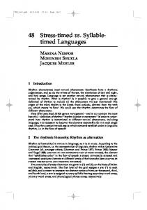
Figure 1. Tool suite for DSML design through semantic anchoring
2. Overview of semantic anchoring A DSML can be formally defined as a 5-tuple L = consisting of abstract syntax (A), concrete syntax (C), syntactic mapping (MC), semantic domain (S) and semantic mapping (MS) [25]. The abstract syntax A defines the language concepts, their relationships, and well-formedness rules available in the language. The concrete syntax C defines the specific notations used to express models, which may be graphical, textual, or mixed. The syntactic mapping, MC: C → A, assigns syntactic constructs to elements in the abstract syntax. The DSML semantics are defined in two parts: a semantic domain S and a semantic mapping MS: A → S. The semantic domain S is usually defined in some formal, mathematical framework, in terms of which the meaning of the models is explained. The semantic mapping relates syntactic concepts to those of the semantic domain.
Although DSMLs use many different modeling and model composition concepts and notations for accommodating needs of domains and user communities, semantic domains for expressing fundamental types of dynamic behaviors are more limited. Broad categories of component behaviors can be represented by behavioral abstractions, such as Finite State Machine, Timed Automaton and Hybrid Automaton. This observation led us to propose a semantic anchoring infrastructure for defining behavioral semantics for DSMLs. The development of a semantic anchoring infrastructure includes the following tasks [11]: 1. Defining a set of modeling languages {Li} for the basic behavioral abstractions and developing the precise specifications for all components of Li = . We use the term “semantic units” to describe these basic modeling languages.
Proceedings of RTAS 2006, San Jose, CA April 4-7, 2006 2. Defining the behavioral semantics of an arbitrary L = modeling language by specifying the MA: A→Ai mapping. The MS: A→S semantic mapping of L is defined by the MS = MSi ○ MA composition, which indicates that the semantics of L is anchored to the Si semantic domain of the Li modeling language. Figure 1 shows our tool suite to facilitate DSML design through semantic anchoring. It comprises (1) the ASM-based common semantic framework for specifying semantic units and (2) the MIC modeling (GME) and model transformation (GReAT) tool suites that support the specification of transformation between the DSML metamodels and the Abstract Data Models used in the semantic units. In the rest of this section, we give a short introduction to the related tools. Readers can refer [11, 14] for detailed knowledge about the semantic anchoring tool suite. We selected Abstract State Machine (ASM) [15], formerly called Evolving Algebras [16], as a formal framework for the specification of semantic units. General forms of behavioral semantics can be encoded as (and simulated by) an abstract state machine [15]. AsmL [18], developed by Microsoft Research, provides specification language simulator, test-case generation and model checking tools for ASMs. The Generic Modeling Environment (GME) tool suite [12] is employed for defining the abstract syntax metamodels for DSMLs using the UML/OCL [4, 18] – based MetaGME as the metamodeling language. The MA: A→Ai semantic anchoring of L to Li is defined by model transformation rules expressed in the UTM (Unified Transformation Model) language of the GReAT tool suite [13]. In UMT, model transformations are expressed as graph transformations that can be executed (both in interpreted and compiled form) by the GReAT engine. In summary, semantic anchoring specifies DSML semantics by the operational semantics of selected semantic units (defined in AsmL) and by the transformation rules (defined in UTM). The integrated tool suite [14] enables that domain models defined in a DSML are simulated according to their “reference semantics” by automatically translating them into AsmL data models using the transformation rules.
3. A semantic unit for timed automata based modeling languages Timed Automata [19] were proposed for modeling the behavior of real-time systems over time. Several analysis tools for real time systems, such as UPPAAL [21], IF toolset [22] and Kronos [23], were developed
based on this modeling approach. They use timed automata based modeling languages (TAMLs) that have tool dependent differences in their approach to express communication among concurrent components and action (transition) priorities. The similarities and differences in the syntax and semantics of varied TAMLs may confuse designers and lead to mistakes. There are plenty of examples for language constructs that may appear similar while they express essentially different semantics and language constructs that appear different but have essentially the same semantics. In this section, we propose a priority-oriented Timed Automata Semantic Unit (TASU) as a common semantic model for TAMLs. We propose that semantics of different TAMLs are defined by specifying the transformation between them and TASU. The explicit representation of transformation rules, the formal operational semantics specification of TASU and the behavioral simulation support allow designers understanding and comparing languages with different timed automata semantics and help the integration of different analysis tools in design flows.
3.1. Overview of TASU A timed automaton is a finite-state automaton equipped with a finite set of clock variables [19]. In this original specification a strong synchrony assumption is adopted for time progress, which means that all clock variables progress at the same rate. Transitions are executed instantly and time progresses only when an automaton is in a location. Constraints on clock variables can be used as conditions for enabling transitions. Transitions can be associated with actions that reset clock variables. In order to facilitate modeling concurrent real-time systems, many TAMLs (e.g. UPPAAL and IF) extend the original timed automata with parallel composition to specify networks of automata. The supported communication mechanisms vary across tools. In general, such communication can be categorized into three categories: shared variables, synchronous and asynchronous communication. In most cases, asynchronous communication can be modeled by synchronous communication plus automata representing buffers. To keep balance between the semantic expressivity and complexity, our proposed semantic unit directly supports communication only through shared variables and synchronization. If needed, asynchronous communication is specified via mapping to the synchronous communication through model transformation. Transition priority is a very useful concept for reducing non-determinism in models and for modeling
Proceedings of RTAS 2006, San Jose, CA April 4-7, 2006 interrupts or preemption in real-time systems. Also, dynamic priorities match well with practical implementations of real-time systems. Priority information is implicitly expressed in certain language constructs of a TAML. For instance, an urgent location in UPPAAL indicates that transitions out from this location have higher priority than that of time progress [21]. The priority of a transition is, in general, time dependent. For example, a delayable transition in IF semantically implies that the priority of this transition jumps to a higher value than that of time progress when the enabling condition of this transition is about to be violated by time progress [22]. Although priority hierarchies of TAMLs are tooldependent, they have many common features. In order to compare and integrate models from varied TAMLs, we need to establish a generic priority scheme that is capable of capturing all these priority hierarchies. A fundamental common feature is that all these tooldefined priority schemes are built with respect to the time progress priority, which enables modeling urgency of actions in real-time systems. An urgent action in real-time systems is modeled as a transition having higher priority than that of time progress. In some TAMLs, urgent transitions are additionally divided into two groups: normal urgent transitions and most urgent transitions. A most urgent transition prohibits the execution of any other transitions as well as time progress. This enables modeling of an atomic action that is composed of a sequence of sub-actions. In TASU, the priority hierarchy has three layers: the bottom priority (the time progress priority), the top priority (the priority to model atomic actions), and the urgent priority, which has a series of urgency degrees. We will show that this priority hierarchy is capable of expressing varied priority hierarchies defined by TAMLs. In the proposed TASU, a real-time system contains a set of concurrent components. Each component is modeled by a timed automaton. Components communicate among each other through shared variables and synchronization. The priority of an action can be dynamically updated with respect to time progress. Enabled actions with higher priorities will block actions with lower priorities. Non-determinism is supported by allowing multiple enabled actions with the same priority. Based on the timed automata model defined in [20], we present an abstract mathematical definition for a timed automaton in the semantic unit. Given a finite set of variables V, a valuation for the variables is a function ν∈ℜV that assigns a value for each variable from the domain of real numbers. If |V| = n the valuation can be represented as the vector
v ∈ ℜ n . We denote the valuation for an element i∈ N
as vi. A linear expression φ (v) over V can be expressed as ∑ ai vi where a i ∈ Ζ (integers) and v i ∈ V . A linear constraint γ is of the form φ (ν ) op c where φ (v) is a linear expression over V, op ∈ {=, , ≥} and c ∈ Ζ. We denote the set of linear constraints over the set of variables V as LC(V). A linear assignment over V is defined as Av + c , where A is an n × n matrix with coefficients from Z and c is a vector of Z n . We denotes a set of linear assignment over the set of variable V as LA(V). The set of simple assignment SA(V) corresponding to the case when all entries of A are 0 and c ≥ 0 . A timed automaton is defined over a set C of resetable clocks and a set V of integer variables. A timed automaton in the semantic unit is a 7-tuple C , V , Σ, L, l 0 , E , Pr i where: • C is a finite set of n clock variables, • V is a finite set of integer-valued variables, • ∑ is a finite set of symbols defining the system events, • L is a nonempty set of locations, • l 0 ∈ L is the initial location, •
E ⊆ L × ∑ ×LC(C ∪ V ) × SA (C ) ∪ LA(V ) × L is a
set of edges. A edge l , α , ϕ , β , γ , l ′ represents a transition from location l to location l’ on symbol α. ϕ is a guard over clock and integer variables. β represents simple assignment for clock variables and γ is linear assignment over integer variables, • Pr i : E × R n → N + is a map that assigns to each edge its priority, which is a non-negative integer value, with respect to a give clock evaluation v ∈ R n , so that Pr i (e, v) is the priority of edge e at clock value v. A state of the timed automaton is defined as (l , c, v) , where l ∈ L , c, v are valuation of the clock C and integer V variables, respectively. The set of all α state is denoted S. The ⎯⎯→ step relation denotes a jump transition which is a discrete and instantaneous transition that changes the location of the automaton as well as the assignment of the integer variables and t ⎯→ step relation denotes a time clocks. The ⎯ transition that advances all clock variables at the same value. A time transition may affect the priority of edges through the function Pri. The priority of a time transition is assumed a constant value, zero. The semantics of a timed automaton model M = C , V , Σ, L, l 0 , E , Pr i in TASU is given as a
Proceedings of RTAS 2006, San Jose, CA April 4-7, 2006 transition system TM = ( S , s 0 , →) where S is the set of states, s0 is the initial state where c0 = 0, and the step relation → is the union of the jump transition: α (l ′, c ′, v ′) iff • (l , c, v) ⎯⎯→ ∃ e = l , α , ϕ , β , γ , l ' ∈ E such that
o ϕ (c, v) = true ∧ c ′ = β (c) ∧ v ′ = γ (v) , and o ∀ e′ = l , α , ϕ ′, β ′, γ ′, l ′′ ∈ E ,
ϕ ′(c, v) = true ⇒ Pr i (e, c) ≥ Pr i (e′, c) . and time transition: t • (l , c, v) ⎯ ⎯→ (l , c + t , v) iff ∀ e = l , α , ϕ , β , γ , l ' ∈ E and ∀ 0 ≤ t ' ≤ t , ϕ (c + t ′, v) = true ⇒ Pr i (e, c + t ′) = 0 . A run of the timed automata is a finite or infinite sequence of alternating jump and time transition of α1 t1 t2 α2 s1 ⎯⎯→ s 2 ⎯⎯→ s 3 ⎯⎯→ s4 L . TM : ρ = s 0 ⎯⎯→ The operational semantics for TASU is specified as a Control State ASM [15]. The specification includes three parts: an Abstract Data Model, Operations and Transition Rules. In the ASM formulation, the Abstract Data Model captures the abstract syntax of a modeling language defined for TASU. The Operations and Transition Rules form a model interpreter that specifies the operational semantics. An instance of the Abstract Data Model (we will refer to it as Date Model), Operations and the Transition Rules form an ASM that specifies the model semantics. We document the specification in AsmL for the sake of readability. Because of page limitation, we present only a part of the specification together with short explanations. For a detailed exposure to the AsmL specification, please refer to [14].
3.2. Abstract Data Model We choose to define the Abstract Data Model for TASU by using AsmL classes [17]. The Clock defines a type for clock variables. The variable field time represents the logical time of a clock variable. All clock variables progress at the same rate. For the purpose of model simulation, we introduce an AsmL constant CLOCKUNIT to set the granularity of time progress. A system might define a set of global clocks and each component might define its own local clocks. The globalClocks is an AsmL set containing all global clocks. Note that the set globalClocks is empty in the specification of the Abstract Data Model. Elements of this set are model-dependent and will be specified in instances of the Abstract Data Model (in the Data Models). When the Boolean variable TimeBlocked is set to true, the system explicitly blocks time progress.
class Clock var time const CLOCKUNIT var globalClocks var TimeBlocked
as as as as
Double = 0 Double Set of Clock = {} Boolean = false
Location and Transition are defined as first-class types. The constant fields blockTime and setPrior in Transition indicate whether this transition is a special transition to block time progress or to set the priority of the owner automaton to the top priority. If any automaton is in the top priority, enabled transitions in all other automata as well as time progress will be prohibited. Note: these two special transition types are adopted for software implementation convenience. They are also denoted as edges whose source and destination locations are the same. (See further explanation in the operational semantics specification.) A transition can participate in a synchronous communication in one of two roles: SEND and RECEIVE. class Location const id const initial const outTransitions class Transition const id const blockTime const setPrior const dstLocationID enum SYNROLE SEND RECEIVE
as String as Boolean as Set of Transition as as as as
String Boolean Boolean String
The class SignalChannel captures the synchronous communication among automata. The variable field senders and receivers record a set of signal senders and receivers, respectively. The Boolean field broadcast indicates whether the signal channel is a broadcasting channel. In a broadcasting channel, a sender publishes events without waiting for receivers and the event will be broadcasted to all receivers that are waiting for it. The event will be lost, if there are no receivers that are waiting for it. A non-broadcasting channel is enabled to fire when there are at least one sender and one receiver that are waiting. Only one sender and one receiver can take part in a synchronization communication and a synchronization pair is chosen non-deterministically when several combinations are enabled. class SignalChannel const id as const broadcast as var senders as (TimedAutomaton, var receivers as (TimedAutomaton,
String Boolean Set of Transition) = {} Set of Transition) = {}
The abstract class TimedAutomaton defines the base structure for a timed automaton. The variable field currentLocation refers to the current location of an
Proceedings of RTAS 2006, San Jose, CA April 4-7, 2006 automaton. Initially, it refers to the AsmL null value. The AsmL construct Location? indicates that the value of this field may refer to either a Location instance or to the null value. When an automaton is in the top priority layer, its prior field is set to true. The TimedAutomaton class also holds a set of readonly abstract properties and abstract methods. These abstract properties define an abstract data structure that captures the tuple structure of an automaton. For example, the abstract property syns is a map whose domain consists of transitions that require synchronization. If t is a transition in this domain, then syns(t) is a 2-tuple whose first element refers to the corresponding signal channel and whose second element indicates whether t acts as a sender or a receiver. The abstract method TimeGuard(t) and DataGuard(t) return a Boolean-valued expression of time conditions and data conditions that are attached to the transition t, respectively. The abstract method DoAction(t) executes actions attached to a transition t. The abstract method Priority(t) returns the priority of a transition. Since the priority value of a transition might be dynamically updated, Priority(t) returns either an integer value or an integer-valued expression. All these abstract members of TimedAutomaton are modeldependent specifications for the semantic unit and will be further specified by a concrete automaton template. abstract class TimedAutomaton const id as String var currentLocation as Location? = null var prior as Boolean = false abstract property locations as Set of Location get abstract property transitions as Set of Transition get abstract property localClocks as Set of Clock get abstract property syns as Map of get abstract TimeGuard (t as Transition) as Boolean abstract DataGuard (t as Transition) as Boolean abstract DoAction (t as Transition) abstract Priority (t as Transition) as Integer
The AsmL class RTSystem captures the top-level structure of a real-time system. The components field holds concurrent components contained in the system. Each component is an instance of a concrete automaton template. These components communicate through a set of signal channels, which are recorded in the field signalChannels. class RTSystem const components as Set of TimedAutomaton const signalChannels as Set of SignalChannel
3.3. Operational semantics
We are now ready to specify the operational semantics for TASU as AsmL Operations and Transition Rules, which interpreter the Abstract Data Model defined above. The specifications start from the top-level system, and proceed toward the lower levels. An active RTSystem instance executes enabled transitions or advances time. The operational rule Run of RTSystem specifies the top-level system operations as a set of updates. (Note that the AsmL keyword step introduces a set of operations that updates the ASM states. All operations within a single step occur simultaneously.) The rule Run first initializes all components in the system, which makes the field currentLocation of each component refer to its initial location. The next step is executed until the operations inside the step causes no state changes in the ASM (fixpoint). class RTSystem Run() step Initialize() step until fixpoint step RegisterSignalChannels() step let T as (TimedAutomaton?, Transition?) = GetNextTransition() step if TimeBlocked then if T.Second = null then error("The system is blocked.") else T.First.DoTransition(t.Second) else if T.Second = null then TimeProgress() else if T.First.GetPriority() = 0 and RandomDecisionIsTrue() then TimeProgress() else T.First.DoTransition(t.Second)
Within the loop, the rule first registers all current transitions that are enabled to participate in synchronization to the corresponding signal channels. A transition is called current if it is a transition out from the current location of an automaton. Then the signal channels are able to judge whether they are enabled to trigger communication among components. Next, the rule checks all current transitions and select an enabled one that has the highest priority as a candidate for the next execution. If such enabled transitions exist, the selected candidate is recorded as a 2-tuple whose first element refers a component and whose second element refers an enabled transition in that component. Otherwise, the second element of the 2-tuple must be a null value. Afterwards, the rule checks a set of current system properties and makes decisions on whether to execute the candidate transition or to advance time. There are four possible cases: 1. If time progress is explicitly set blocked and the system has no enabled transitions, the rule returns
Proceedings of RTAS 2006, San Jose, CA April 4-7, 2006 an error message that indicates the system will be blocked indefinitely. 2. If time progress is explicitly set blocked and the system has a candidate transition, this candidate transition is executed. 3. If time progress is allowed and the system has no enabled transitions, the rule forces time progress. 4. If time progress is allowed and the system has a candidate transition, the rule checks the priority of this candidate transition. This candidate transition is executed when it has a higher priority than that of time progress. Otherwise, the rule randomly determines to advance time or to execute the candidate transition. The rule GetNextTransition of RTSystem describes the algorithm for the system to select a candidate transition for the next execution. It first looks for components that are in the top priority. If one exists, the subrule GetEnabledTransition of TimedAutomaton is then applied to select an enabled transition from this component. If this component has no enabled transitions, GetEnabledTransition returns a null value. The system will be blocked indefinitely, since a component in the top priority blocks enabled transitions in other components as well as time progress. If no component is in the top priority, the rule chooses a transition with the highest priority from enabled transitions in all components. In short, a block time transition has higher priority than normal transitions. For a normal transition, the larger its priority value, the higher its priority. class RTSystem GetNextTransition() as (TimedAutomaton?, Transition?) choose c in components where c.prior return (c, c.GetEnabledTransition()) ifnone let EC = {c | c in components where c.HasEnabledTransition()} choose c in EC where c.GetEnabledTransition().blockTime return (c, c.GetEnabledTransition()) ifnone choose c in EC where not (exists c2 in EC where c2.Priority() > c.Priority()) return (c, c.GetEnabledTransition()) ifnone return (null, null)
The operational rule IsTransitionEnabled of TimedAutomaton examines if a transition is enabled or not. The subrule IsSynEnabled(t) checks whether the corresponding signal channel is ready to fire. If the transition t does not require to synchronize with other transitions, IsSynEnabled(t) returns true. The block time transition and the setPrior transition are two special transitions. A block time transition has an implicit guard, which checks if the TimeBlocked field is false, and has an implicit action that sets the TimeBlocked field to true so that all components know
time is blocked. A setPrior transition has no guard, but has one more implicit action that sets its owner component as a prior component. It must be enforced immediately after a component enters a location that has a setPrior transition. A setPrior transition is always considered disabled by the rule IsTransitionEnabled of TimedAutomaton, since it must already be executed if a setPrior transition exists in the current location. After an execution of a normal transition, the prior field of a component and the TimeBlocked field of the system will be reset to false if the new current location has no setPrior transition. abstract class TimedAutomaton IsTransitionEnabled (t as Transition) as Boolean if (TimeBlocked and t.blockTime) or t.setPrior then return false else return t in currentLocation.outTransitions and TimeGuard(t) and DataGuard(t) and IsSynEnabled(t)
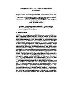
Figure 2. The automaton metamodel for TASU
3.4. Modeling language specification for TASU The semantic anchoring tool suite as shown in Figure 1 assumes that model transformation between a TAML and TASU is defined in terms of their abstract syntax metamodels [11] using the graph transformation language UMT and the GReAT tool. Consequently, we need to create an “interface” toward the semantic anchoring tool suite by defining a metamodel for TASU. Since the metamodeling language in MIC is UML/OCL (or MOF), the metamodel is simply the UML/OCL based representation of the Abstract Data Model defined in Section 3.2. The automaton metamodel (a part of TASU metamodel) in Figure 2 shows the close correspondence between the two. In order to obtain a graphical modeling environment for TASU, we also specified the metamodel in MetaGME. The MetaGME specification adds concrete syntax information to the metamodel and can be used for “meta-programming” the GME tool suite to create a
Proceedings of RTAS 2006, San Jose, CA April 4-7, 2006 modeling environment. (Detailed specifications and the full environment can be downloaded from [14].) The semantic anchoring tool suite provides a translator, which translates TASU models built in the GME modeling environment into AsmL domain models (i.e. instances of the Abstract Data Model). To illustrate this process, we show in Figure 3 a simple TASU automaton model and its equivalent representation in AsmL. This generated AsmL data model can be simulated according to the operational semantics defined in Section 3.3.
Figure 3. A TASU automaton (ComponentKindA) class ComponentKindA extends TimedAutomaton L0 as Location = new Location ("L0",true, {T1,TBT}) L1 as Location = new Location ("L1",false,{T2,TSP}) L2 as Location = new Location ("L2", false, {}) T1 as Transition = new Transition ("T1",false,false,“L1”) T2 as Transition = new Transition ("T2",false,false,“L2”) TBT as Transition = new Transition ("TBT",true,false,“L0”) TSP as Transition = new Transition ("TSP",false,true,“L1”) c as Clock = new Clock () override property locations as Set of Location get return {L0, L1, L2} override property transitions as Set of Transition get return {T1, T2, TBT, TSP} override property localClocks as Set of Clock get return {c} override property syns as Map of get return { T1 -> (EXIT, SEND)} override TimeGuard (t as Transition) as Boolean match t.id "T1" : return c.time >= 10 "T2" : return c.time == 0 "TBT": return c.time >= 20 _ : return true override DataGuard (t as Transition) as Boolean match t.id _ : return true override DoAction (t as Transition) match t.id "T1": c.time := 0 _ : skip override Priority (t as Transition) as Integer match t.id _ : return 0
In the TASU domain modeling environment, a normal transition is represented as a continuous directline. Information attached to a normal transition includes five segments ordered in sequence: a signal channel, a time guard, a data guard, priority and actions. The corresponding segment is left empty if a transition does not have that information. A block time transition (e.g. TBT in Figure 3) is represented by a dot direct-line. Only a time guard can be attached to a block time transition. A dash direct-line is utilized to represent a setPrior transition, e.g. TSP in Figure 3. No additional information might be put on a setPrior transition, since the information attached to a setPrior transition is predefined by the semantic unit and can not be modified by a component. OCL constraints are specified to guarantee the well-formedness of domain models.
4. Semantic anchoring to TASU Semantic anchoring of a TAML means defining the transformation to TASU. In MIC, this transformation is defined in terms of the TAML and TASU metamodels. As it is shown in Figure 1, the specification of the transformation (which is the transformational semantics of the selected TAML) can be directly used for automatically generating a model transformer, which can translate TAML models into TASU models. (The TASU models (as we showed it above) can then be translated into AsmL data models if we want to obtain a simulation using the specification of the semantics.) In this section, we illustrate the semantic anchoring from the UPPAAL and IF languages to TASU. It must be noted that we do not consider in this paper the verification of the semantic equivalence between our specification and those used internally by the tools. We also have to restrict the description of the transformations due to space limitations. The full specifications by using our semantic anchoring tool suite can be downloaded from [14].
4.1 Semantic anchoring for the UPPAAL language A trivial one-to-one mapping can realize the anchoring for those modeling constructs that are the same both in the UPPAAL language and in TASU. In this section we show examples for transformation rules that map modeling constructs that exist in UPPAAL but not in the semantic unit. 4.1.1. Location invariants. Time constraints put on locations are called location invariants. An automaton may remain in a location as long as the clock variables satisfy the invariant condition of that location. When the invariant condition is about to be violated by time progress, the automaton must be forced to leave this location.
Figure 4. Semantic anchoring for a UPPAAL automaton with location invariants
A location with an invariant condition in UPPAAL is anchored to a location in TASU with a blocked time transition where the time guard is the critical condition. As shown by the example in Figure 4, a simple
Proceedings of RTAS 2006, San Jose, CA April 4-7, 2006 UPPAAL time automaton whose start location has an invariant condition on the clock variable c can be translated to an equivalent automaton in TASU. We briefly explain the behavior of the automaton in Figure 4 (b). Before the critical condition, c == 5, is satisfied, the block time transition TBT is not enabled and the automaton may stay in or leave the location start. If the automaton is still in the start location when the critical condition is reached, the block time transition TBT is taken immediately. Now time is not allowed to progress until the automaton leaves the start location. 4.1.2. Urgent/Committed locations. There are three kinds of locations in UPPAAL that are normal locations with or without invariants, urgent locations and committed locations. Time may not pass in urgent or committed locations. However, urgent locations allow instantaneous interleaving with other components. In UPPAAL, a location marked ∪ denotes an urgent location and the one marked C is committed.
4.1.3. Urgent synchronizations. A signal channel in UPPAAL may be declared as urgent. If a transition with an urgent channel is enabled, time delay must not occur before this transition is taken. TASU does not have the urgent channel concept, but the same effects can be achieved through setting the priority of a transition to be an integer greater than zero (depending on the relative priority with respect to other actions). Figure 7 shows an example to illustrate the transformation for urgent synchronization. Note that the signal channel EXIT in (a) is declared elsewhere as an urgent channel, while the one in (b) is only a normal channel in TASU.
Figure 7. Semantic anchoring for a UPPAAL automaton with urgent synchronization
4.2. Semantic anchoring for the IF Language
Figure 5. Semantic anchoring for a UPPAAL automaton with urgent locations
In the anchoring, an urgent location is mapped to a normal location plus a block time transition with no time guard. Figure 5 shows a simple example. In the figure, (a) is a UPPAAL automaton, and (b) is the anchoring automaton in TASU.
Figure 6. Semantic anchoring for a UPPAAL automaton with committed locations
An automaton in a committed location blocks both time progress as well as enabled transitions in all other automata. This functionality is equivalent to a setPtior transition in TASU, which sets the priority of the owner automaton to the top priority. As shown in Figure 6, (a) is a UPPAAL automaton and (b) is the semantic equivalent automaton in TASU after transformation.
The IF language [22] is another well-known TAML to model asynchronous communicating real-time systems. In IF, a real-time system contains a set of processes, which are running in parallel and interacting through asynchronous signal routes. Each process is modeled by an extended timed automaton. This section is focused on the semantic anchoring for the IF specialized language constructs including: transitions with three types of deadline, unstable states and asynchronous signal routes with different policies. 4.2.1. Lazy/Delayable/Eager transitions. The IF language does not support location invariants explicitly, but the same behavior can be achieved through utilizing transitions with different deadlines. An IF transition may have one of three types of deadlines (lazy, delayable and eager), which indicates the priority of a transition with respect to time progress. A lazy transition is never urgent and always allows time progress. An eager transition is urgent and prohibits time progress as soon as it is enabled. A delayable transition becomes urgent when it is about to be disabled by time progress and allows time progress otherwise. A lazy transition is equivalent to a normal transition in TASU with a priority value zero. The same behavior for an eager transition can be achieved by setting the priority of the corresponding transition in TASU to be an integer greater than zero (depending on the relative priority with respect to other actions). A delayable transition implies that the priority of this transition jumps to a higher value than that of time
Proceedings of RTAS 2006, San Jose, CA April 4-7, 2006 progress when the enabling condition of this transition is about to be violated by time progress. An example for the transformation is shown in Figure 8. Note that the transition T1 in (a) is an IF delayable transition while the one in (b) is a normal transition in TASU. We give a briefly explanation for the behavior of the IF automaton in (a). During 10