A Structural Health Monitoring Method Based On Magneto-optic Imaging Technology Yu Hua Cheng1
Li Bing Bai3
School of Automation Engineering University of Electronic Science and Technology of China Chengdu, Sichuan 610054, China 1:
[email protected]
School of Automation Engineering University of Electronic Science and Technology of China Chengdu, Sichuan 610054, China 3:
[email protected]
Yi Ming Deng2
Gui Yun Tian4
Department of Electrical Engineering, Department of Bioengineering, College of Engineering and Applied Science, University of Colorado-Denver 2:
[email protected]
School of Electrical, Electronic and Computer Engineering Newcastle University 4:
[email protected]
Abstract—A magneto-optic imaging system is presented in this paper to detect invisible and buried subsurface flaws in metallic structural, which can be used to monitor structural health. The resulting power of the MO imaging system is mainly given by the parameters of the MO thin films, the magnetic excitation device and image processing algorithms. In this paper, the choice of the MO thin films, the design of the magnetic excitation device and the development of the image processing approaches are introduced in detail. Experimental tests have been done and the method presented is evaluated by the experimental results.
which is laid close to the tested specimen .The intensity of the linear polarized light is correspondingly changed when being reflected by the polarization beam-splitter. The polarizer filters the influence of miscellaneous light, and the magneto-optic (MO) image is received by CCD after being amplified. Finally, the image is analyzed and processed by the computer.
Keywords: MO thin films; intermittent impulse signal; Magnet excitation device; Image processing I.
INTRODUCTION
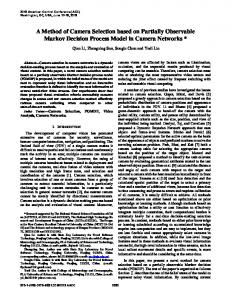
Magneto-optic imaging system appears as a good alternative to conventional eddy current (EC) and magnetic flux leakage (MFL) for inspecting the surface and sub-surface defects in metallic specimens. By imaging the reflected polarized light through the magneto-optic thin film, defects can be imaged. Fig.1 shows the principle configuration of the magneto-optic testing device, which adopts the semiconductor laser instrument as the light source divided into two beams by the polarization beam-splitter: one as the transmission light is the linear polarized light used in the experiment; another is the reflection light which is not used in the experiment. The linear polarized light focuses on the surface of the tested specimen by the object lens. It penetrates the object lens again after reflecting. Its’ direction is parallel to that of the original one. Passing through the (1/2) λ plate, the polarized direction of the light rotates by 90o. The light could only be reflected and could not penetrate the polarization beam-splitter, which is convenient for the imaging sensor to receive and can prevent the reflecting light from improperly influencing the laser instrument. On the coil being excited, the eddy-current-induced magnetic field conceives the information of the defects, and the polarized direction of the linear polarized light is changed twice when passing through the Faraday rotator glass (FRG), Corresponding author: College of Engineering and Applied Science, University of Colorado-Denver,
[email protected]
978-1-4577-1772-7/12/$26.00 ©2012 IEEE
Figure 1. Principle configuration of the magneto-optic device. II.
RESULTS AND DISCUSSION
Fig.2 shows a piece of aluminum slice of 20×10×10mm (length, width, height), which is detected by the device. A 0.2mm wide groove is made by linear cutting, and the surface without groove is ground smooth. The detecting head is fixed above the groove. Fig. 3 shows an image acquired by the device shown in Fig. 1. The image shows the groove, but it is not clear and has a number of noises.
Figure 2. Specimen: crack detection.
Figure 4. Multi-path propagation of light.
Figure 3. The MO images.
Figure 5. Film with transmission increasing film and reflection increasing film.
As shown in Fig. 4, some noises are caused by the multi-path propagation of light. Some light is not modulated by the eddy-current-induced magnetic field and reflected from the upper surface of the MO film directly. Since the lower surface of the MO film and the upper surface of the specimen are not infinitely smooth, some reflected light doesn’t stay parallel to the other. Consequently, the light reflected by different areas is mixed together. The device use single frequency sinusoidal excitation which heats the coil and samples. Further more, the coil is excitation with an amplifier, which limits the frequency and intensity of the magnetic field. As a result, the polarization does not change enough. Except the factors presented above, the original images suffer from numbers of other interference factors, such as variations in the incident light and variations in the YIG’s magnetic domain. III.
IMPROVEMENT
To improve the accuracy and resolution, a new MO film and an excitation device based on power factor correction (PFC) are made, and an image processing method is proposed. A. MO Film Fig.5 shows the new film, which has a transmission increasing film and a reflection increasing film. The film decreases the reflection of the upper surface, and increases the reflection of the lower surface. Consequently, the noises caused by multi-path propagation of light are depressed. B. Excitation Device In order to reduce the working temperature of the coil and enhance the magnetic field, an intermittent square pulse is selected as the type of excitation current which has a higher exciting efficiency than does a sine wave.
Fig.6 shows a schematic diagram of the PFC circuit, which consists of a boost circuit and a power regulating circuit. The boost circuit converts the alternating current (AC) into directing current (DC), and provides a DC voltage for the power regulation part. The voltage varies from 311V to 450V with the variation of duty ratio of the MOSFET Q, when the input AC is 220V/50Hz. The circuit can be regarded as a constant voltage source for the next part, since the DC voltage can be fixed in any voltage between 311V-450V with variation in little range. The PFC utilizes the active switched AC / DC Conversion Technique, with a DC / DC switching converter between the rectifier and filter capacitor. The input current is regulated to a sinusoidal wave which has the same frequency and phase with the grid voltage. Consequently, the harmonic component decreases and the power factor increases effectively. The power regulating circuit converts DC into intermittent square pulses, which excites the coil. A Pulse Width Modulation (PWM) waveform is applied to two pairs of IGBT Q1, Q4 and Q2, Q3. The bus voltage Uin provided by Boost circuit is converted to a square wave voltage Uo which is the output of the excitation device. According to a signal given by the host computer, an intermittent square pulses is generated.
Figure 6. Schematic diagram of the PFC circuit.
C. Image Processing In order to estimate the defect, the position and shape of the flaws must be detect exactly. This paper presents Wavelet Transform (WT) to suppress the noises and locate the flaws The density of any point (c(x, y)) of the image is f (x, y). The WT is
Wf ( x, y ) = f ( x, y ) ⊗ ϕ ( x, y ) , where ϕ ( x, y ) conditions:
is the Mother Wavelet and meet the
^
(2π ) 2 ∫∫ [ϕ (ω x , ω y )]2 /(ω x2 , ω y2 )dω x dω y < ∞ ,
ϕ1 ( x, y ) = ∂θ ( x, y ) / ∂x , ϕ 2 ( x, y ) = ∂θ ( x, y ) / ∂y ,
where
θ ( x, y )
(1)
(2)
IV.
SECOND RESULTS AND DISCUSSION
A. Magnet Excitation Fig. 7 shows the intermittent square pulse of the excitation. The duration of the pulse is referred to as t0 and the intermittent time t. Here t is equal to 1.5t0, and the frequency of the pulse is 2 kHz. Both of them are empirical values, which are suitable for image acquisition and low temperature-rise. B. Image Processing Fig. 8 shows a MO image acquired by CCD, and its optimized images converted by image processing. Fig. 8 (a) is the original MO image. Fig. 8 (b) is the optimized image. Both Fig. 8(a) and Fig. 8(b) show the groove clearly. Further more, Fig. 8(b) locates the edges.
(3) (4)
is a smooth function. Then
W1 f ( x, y ) = f ( x, y ) ⊗ ϕ1 ( x, y ) , W2 f ( x, y ) = f ( x, y ) ⊗ ϕ 2 ( x, y ) .
(5) (6)
|W1(x, y)| has the local maximum at the regular point of x direction; |W2(x, y)| has the local maximum at the regular point of y direction. Define
mf ( x, y ) = {[W1 f ( x, y )]2 + [W2 f ( x, y )]2 }1/ 2 . (7)
Figure 7. Schematic diagram of the intermittent square pulse
If
mf ( x, y ) > m0 ,
(8)
where m0 is a threshold, the point c(x, y) is considered as the edge point of the flaws. In order to improve the accuracy, multi-scale WT is used. The mother wavelets are
ϕ ks = ϕ k ( x / s, y / s) / s 2 , (k = 1,2) .
(9)
(a) MO image
Then
Wks f ( x, y ) = f ( x, y ) ⊗ ϕ ks ( x, y ), (k = 1,2) , (10) m s f ( x, y ) = {[W1s f ( x, y )]2 + [W2s f ( x, y )]2 }1/ 2 .(11) With the right m0 and s, the flaws can be located exactly.
(b) Optimized image Figure 8. MO image and optimized image.
V.
REFERENCES
CONCLUSION
This paper presents a magneto-optic imaging system, which is suitable to monitor structural health. A new MO film is designed to decrease the multi-path propagation of light and depress the noises of the image effectively. A pulse generator based on PFC is utilized to provide intermittent excitation current for the coil, which has a lower working temperature of the coil and a higher exciting efficiency than does a sine wave. An image processing approach is also presented in this paper, which extracts the contour of the defects clearly from the acquired image. The experimental results have shown that the method is practical. Future work will concern the experimental approach extension including multiple defects detection and image processing method which can ascertain the characters of the defects. ACKNOWLEDGMENT This work is partially supported by the National Natural Science Foundation of China (Grant No. 61102141) and the Specialized Research Fund for the Doctoral Program of Higher Education of China (20100185120005).
[1]
[2]
[3]
[4]
[5]
[6]
[7] [8]
P. Novotný, P. Sajdl and P. Machá, “A magneto-optic imager for NDT applications”, NDT & E International, Volume 37, Issue 8, December 2004, Pages 645-649. Y. H. Cheng, and Z. F. Zhou, “Application of the magneto-optic Faraday effect in NDT” , Insight: Non-Destructive Testing and Condition Monitoring, vol. 48, no. 5, pp. 290-292, May 2006. Z. F. Zhou, and Y. H. Cheng, “Magneto-optic microscope for visually detecting subsurface defects,” Applied Optics, vol. 47, no. 19, pp. 3463-3466, July 2008. Yuhua Cheng, and Ke Rong, “Research on visual detection technology using eddy current magnet excitation device” , 2009 IEEE International Conference on Applied Superconductivity and Electromagnetic Devices, Chengdu, China, pp. 149-151, September 25-27, 2009. Unsang Park, Lalita Udpa and George C. Stockman, ‘Motion-based filtering of magneto-optic imagers’, Image and Vision Computing, Volume 22, Issue 3, 1 March 2004, Pages 243-249. Texas Instruments Incorporated, Average current mode controlled power factor correction converter using TMS320LF2407A, SPRA902A, July 2005. Texas Instruments Incorporated, C28x IQmath Library, pp. 21-24, 2008 Xudong Cui, Shenwei Dong, Ruigen Liu, “Flash Image Edge Detection Using Wavelet”, Detonation and Sock Wave, March, 2001.