Web-based Urban 3D GIS: Virtual Environment of 3D Model Visualization Guoqing Zhou, Zhenyu Tan, Ming Xie, and Jianfeng Tang Laboratory for Earth Observing and Spatial Data Processing, Department of Civil Engineering and Technology, Old Dominion University, Kaufman Hall, Rm. 214, Norfolk, VA 23529, USA Tel: 1-757-683-3619; Fax: 757-683-5655; Email:
[email protected]
Keywords: 3D GIS, City model, Visualization, DBM, DTM, VRML, Web GIS
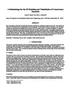
ABSTRACT This paper presents our research results of visualizing 3D city model in a web explorer environment under the supports of digital building model (DBM), digital terrain model (DTM), large-scale true urban orthoimage, and actual building sidewall pictures. A system has initially been designed and developed under a client/server architecture, which integrates Internet GIS with multi-tier web application for creation of 3D city model. The front-end client provides a user interface for setting properties of the 3D model, while the backend server processes the parameters and generates the 3D model, which is then sent back to the VRML-enabled WWW browser for display and navigation. The technology for display and navigation of the 3D model is actually a Java JSP/Servlet technology built under multi-tier web architecture. The data accessing and processing of the technology is through Java programming language to link the displayer with the database where the required GIS spatial data are stored. The results from our experiment demonstrated that this developed architecture is able to display and visualize 3D city data in web environment for public access. Using the sidewall pictures taken from real city buildings, we refill the white walls of urban buildings into a real appearance as seen in our real world city. The player provides several click buttons to change the effect and position of visualization, including rotation, zoom, pan, seek etc. The users can easily to view details of specific building, the entire city in a moving 3 dimensions, to locate a specific building, and so on. superimposed. The system has initially been designed and developed under a client/server architecture, which integrates 1. INTRODUCTION Internet GIS with multi-tier web application for creation of 3D city model. The 3D spatial data such as coordinate elements of The urban GIS model plays an important role in city planning, city buildings are taken as inputs for the 3D model, and communication system design, control and decision-making, as visualization is carried out through virtual reality model well as tourism, etc. The demand for visualization of urban city language (VRML). The front-end client provides a user model and realistic presentation of the real world has been interface for setting properties of the 3D model, while the increased dramatically today. Internet and World Wide Web backend server processes the parameters and generates the 3D (WWW) have been widely applied in delivering, processing, model, which is then sent back to the VRML-enabled WWW and publishing geospatial data. Web-based GIS, which permit browser for display and navigation. The technology for display users to access, retrieve, display and analyze geospatial data and navigation of the 3D model is actually a Java JSP/Servlet over the web, has got a wide variety of applications. In the technology built under multi-tier web architecture. The data recent years, web-based three-dimensional (3D) GIS for accessing and processing of the technology is through Java visualizing geospatial data has attracted many researchers. The programming language to link the displayer with the database operation uses the web as a delivery mechanism, deals with the where the required GIS spatial data are stored. transformation of multi-dimensional geospatial data, information, and knowledge into an effective 3D visual form With this system, user can create 3D scenes and VRML models (Lin et al., 1999; 2000; Belfore et al., 2003; 2002a; 2002b; from 2D spatial data that are stored in GIS databases. A user is 2001a; 2001b; 2000). A few researchers have used different allowed to generate building by supplying related point approaches for this purpose. MacEachren (1998) used VRML coordinate data, and add different types of roofs to the existing 2.0 to model geospatial data, and Java to develop an interface building by inputting building ID. Also user can choose and to interact with the VRML world. Hibbard (1998) designed and customize the texture for the objects. developed the VisAD system, which enable many users to implement the visualization of a shared set of numerical data and computation sources. Lin et al. (1999) and Huang et al. (1999) developed a called GeoVR system, which is a 2. ARCHITECTURE OF WEB-BASED URBAN 3D GIS client/server architecture to enable the interactive creation of a The architecture of web-based urban 3D GIS is designed in 3D scene and VRML model from 2D spatial data by integrating Figure 1. The architecture consists of three-tiered modules. internet GIS and HTML. Rohrer and Swing (1997) suggested The first tier consists of the display layer that includes not only the use of traditional approaches for visualization because of the web browser but also the web server, which is responsible web-based inherent limitation in, such as, the narrow channel for assembling the data into a presentable format. The second of the Internet. tier is the application layer. It consists of some script and program. The third tier provides the second tier with the data This paper presented our initial research results on development that it needs. The tool collect data from the user (the first tier), of a web-based urban 3D visualization application with recent send a request to the web server, run the requested server advances in multimedia capability and networking program (the second and third tiers), package up the data to be technologies. Using downtown Denver CO as protocol, the orthoimage is employed as bottom layer, and objects are
presented in the web browser, and send it back to the browser for displaying (the first tier).
through servlet middleware, and the server is running on the Web server.
Create 3D
Fig. 1. Three-tier client/server architecture of web-based 3D geospatial data visualization Virtual Reality Modeling Language (VRML) has become a popular tool for building 3D representation on client side. A VRML application is typically a hierarchical organization of geometries, sensors, light sources, script methods, and grouping primitives assembled in a meaningful fashion (Web3D Inc., 1998; Brutzman, 1998; Nadeau, 1999). There are various primitives, termed nodes, are ready in VRML. These nodes are capable of directly visualizing a complicated scene, thus it is largely convenient for visualizing urban 3D model. The geometry of the primitives has been defined in VRML with in shape nodes. Sensors are used to associate interactive capabilities. Scripts enable users to implement specific functions. Information is passed between nodes by events whose routes are either explicitly declared or established within Script nodes (Belfore et al., 2002a). VRML has many desirable features to meet user’s needs for describing 3D objects on the WWW for GIS applications (Reddy et al., 1999). A VRML model can be viewed by any web browser that has a VRML plug-in pre-installed. VRML "worlds" can depict realistic or otherworldly places, which can contain objects that link to other documents or VRML worlds on the web. Java web technology is a powerful web development toolkit. Hibbard (1998) used Java technology to support visualization implementation for shared data. Java technology is further improved by supporting servlet technology. Servlets provide the capabilities of cgi-scripts, but superior in execution efficiency, stability and security. Through the Java Development Kit (JDK) API, servlets can connect to server databases. Servlets are software methods that run on the server and can be called up as URLs from the Internet (Belfore et al. 2002a; 2002b). Servlets handles the client requests and dispatches them to the server. With servlet as a middleware, it can build a multi-tier web application. A servlet extends the capabilities of servers that host applications accessed via a request-response programming model. Servlets can respond to any type of request, and are commonly used to extend the applications hosted by Web servers. JSP technology acts as a top layer above Java servlets on the servlet engine. It allows developers to combine HTML code with server-side scripting to create dynamic pages.
2.1 Client Side Architecture The basic architecture of client side is depicted in Fig. 2. This application uses JSP pages to provide front-end interface for client side. The users interact with the interface for their choices. The request from the users is directed to the server
Fig. 2. Three-menu option on client side front end The front end comprises three options. The first choice is for creating 3D VRML model directly from the data stored in the database. The server part of this application will access the data files and load the data automatically into the server, and the server will automatically build a VRML model based on data files and send it back to the client for displaying on the browser. The second choice is for creating single Hexahedron building through point coordinate data input. This system allows the user to make a new building or add a building to an existing model, only if the user input the coordinates of the corners of a building. For example, if an user inputs X and Y-coordinates of the four points of a building, followed by comma “,” then input two Z-coordinate for the building’s top and bottom height, respectively, an building will be created. Also, the user has the choice for choosing the textures for each different face to the building. Modules whose enclosing boxes are not solid may communicate directly with the server. The third choice is for creating roof object through the value provided by the user; it gives the user ability to add a roof object to an existing VRML model. The user first chooses what kind of roof he is interested in, input corresponding data for creating the roof object. When filling the file name field with the VRML model file name, the roof object will be added to the VRML model that is specified by this file name. So with these two extended functionality, user has the option not only build VRML model from database files automatically, but also has the ability to customize the VRML model by manually input the data value. 2.2 Server Side Architecture Our server side architecture is illustrated in Figure 3. The server side would provide functionality, such as, read/write file access on the server, create VRML model and generate content dynamically. Thus, the web server would serve all client requests for generating static and dynamic content. Several software technologies and development packages have been used in this application. These include the JavaTM Development Kit JDK version 1.4, the Java Servlet Development Kit JSDK version 2.2, the Apache Web Server v 4.0.0, and the Cosmo Player version 2.1.1 browser plug-in. The application use Java object oriented design, it will connect and access the database files, process the user input data, and generate VRML model.
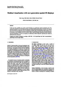
(2) Line objects: which are one-dimensional objects that made by connecting two points, e.g., power line, telephone line, etc.; (3) Face objects: which are two-dimensional objects with area and perimeter characteristics, such as parking lot, grass field, etc.; (4) Body objects: which are three-dimensional objects, such as building, barn, etc. 3.2 Implementation in a Relational Database Fig. 3. Server Side Architecture
3. URBAN 3D MODEL 3.1 Urban 3D Data Structure and Model Visualizing of 3D urban requires a better 3D urban model. Different applications may have different data types and manipulation functions. The geometrical information to be operated to any targeted urban, generally include two types of data: vector data and raster data. An appropriate data model should not only represent the geometrical information, e.g., shape, length, area, etc. but also implicitly or explicitly describe the topological relationship between geometrical object, such as adjacency relations, link relations, positional relations (Wang et al., 1998; Zhou et al., 2000; Zlatanova, 2000). For our model, the urban object is understood as three types of data sets (Figure 4): (1) Digital terrain model (DTM), (2) Original images and orthoimages, in our data structure, texture images are taken as attributes, they are stored an independent database. (3) Spatial objects, such as buildings, roads, waterway.
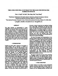
The data structure and model can be implemented by a relational database technology. Each type of object, shown on the above, is defined as a table. The 2D tables are stored in a form of rows and columns, in which each row is identified by a key value. Each row stores the information of one instance of an entity, while each column describes an attribute of the entity. For example, a building table includes three terms. The Building ID is an identification code for a building object. A building is made from a combination of a roof and a wall. The Roof ID points to a Roof table. Roof table has two terms, Component ID and Component Type. It means that a building roof is made from a Component, whose type is either a regular Polyhedron or a Quadric. A Quadric is one of these three: a Cylinder, a Cone and a Sphere. These are three basic types of Quadrics in VRML model. A regular polyhedron is made from Face objects. This can be seen in the Polyhedron table, with a Face ID terms in its table, which points to a Face table. Face table has two terms; they are Texture ID and Point ID. Similarly, they are pointing to Texture table and Point table. Just like Roof object, a Wall object is also made from a Component. Its table relation is just as that of the Roof object.
4. EXPERIMENTS Image
4.1 Data Sets
Point (Power pole...) DEM 3D City Model
Line (Road...)
Objects
(Parking lot...) Regular Polyhedron
Attributes
Quadrics Barn
Points
Face
Buildings Bodies
Cylinder Attributes
Point Radius
Attributes
• Aerial Image The original aerial images were acquired on April 17, 2000 using camera RC30 over downtown of Denver, Colorado. There were totally 6 images from two flight lines. However, Downtown Denver, CO contains a number of high buildings. The image center is located in the downtown area and the available DSM covering its central part.
Height Sphere Attributes
Fig. 4. 3D urban concept model Most important spatial objects in urban area are building. There are four different geometric types of objects. (1) Point objects: which are zero-dimensional objects that have a position but no spatial extension, e.g., power pole, well, etc.;
• Digital Surface Model (DSM) The digital surface model (DSM) available to this study covers Downtown, Denver, CO, which is the central part of the downtown area where a number of high buildings exist. We choose a small part of the imaging area with relatively better DSM for demonstration.
Roof
Texture
… … … … Y RGB … … … … …
PL1 R2
TIF
PL2
…
…
…
Polyhedron
Face
Building
… … … … …
… …
PL1 PL2
…
…
T1 T2
F2
…
…
… Point
X
Y
Z
P1
X1
Y1
Z1
P2
X2
Wall
AP 1 W2
…
P1
PL3
AP 2
PL4
… …
…
…
…
… … … …
Edge
Surface
S1
Road
S2
Road
…
…
…
…
…
P1 P2
…
…
P2 P3
…
Texture
Point
… … … … Y RGB … … … … … TIF
X
Y
Z
P1
X1
Y1
Z1
P2
X2
… … … …
DEM
… … … GRID … T4 … … … … … T3
TIN
Fig. 5. Rational database model for city 3D mode • Digital Building Data (DBD) The 3D coordinates of each building are measured from orthoimage and DSM using EARDAS/IMAGINE v. 6.0. The data were complied into vector data form and stored a relational database as described above.
this section, we will present what kinds of parameters that users need provide to define 3D objects in our system. Our system allows the users to create a single Hexahedron building by inputting several parameters. As shown in Fig. 6., a hexahedron building can be defined by four points and two height values. Each point contains its x and y coordinates.
4.2 Input 3D objects One feature of our system is to allow the users to generate the buildings and add roofs to these buildings. One issue is how to let user input 3D objects. One approach, which is used in our system, is to represent a 3D object as a sequence of parameters. In this approach, the users just need specify several parameters of the buildings or the roofs from our graphic user interface and our system will create the corresponding objects for them. In
Fig. 6. Building’s Parameters The numbers in the cycles of Fig. 6 and all other figures in this section indicate the order of the points.
In our system, we have designed several types of roofs and each type may each shape may require different kind of parameters. In the rest of this section, we will describe the parameters for each type of roofs respectively. In our system, a sharp roof (Fig. 7.) and a house roof (Fig. 8.) can be defined by 5 and 6 points respectively. Each point contains its x, y and z coordinate values. 0
1
0
3 4 2
1
Fig. 7. Sharp Roof
The client side also designs a GUI for users to add various roofs to an existing building implemented by VRML model (Fig. 12). Users first choose what type of roof they are interested in, and then input corresponding coordinates for creating the roof. Recently, we have designed five types of roofs, sharp roof, cone roof, etc. The five types of roofs are stored in roof database. Users can call the roof ID, corresponding to the VRML model ID, the specific roof will be automatically added to the VRML model that user specified.
4
3
2
5
Fig. 8. House Roof
As shown in Fig. 9. , a round roof in our system can be defined by its original point, its bottom radius and its height. The point is represented by its x, y and z coordinates.
Fig. 9. Round Roof
Fig. 11. Client front interface for generating building object
From geometry view, a four-angle roof in our system (as shown in Fig. 10.) is same as a hexahedron building. Not suprisingly, a user can define a four-angle roof in the same way as to define a hexahedron building, which is described in the previous part of this section.
Fig. 10. Four Angle Roof We have already introduced how to define the shape of the 3D object in our system. In addition, our system also allows users to specify the textures for the faces of the object by choosing textures pictures from our database. 4.3 GUI Interface We have developed a graphic user interface, which let customer to create the building, roof, and wall textures. • Customizing Building A called 3D Model Builder, has been developed at client side (see Figure 11). A user only input the building corner coordinates and height from client side, the request is sent to server side. The server will visualize the building by VRML model. On the other hand, the spatial database contains building data, user take advantage of menu for the option to build the building via VRML model from database files automatically. • Customizing Roof
Fig. 12. Client front end for making roof object • Customizing Texture The client side also designs a GUI for users to stick texture image onto the wall of an existing building implemented via VRML model. A texture image database has been established, and various texture images are displayed in the interface. Users first choose the texture images what they are interested in, and then input texture image ID, and Building ID and wall ID, the texture image will be automatically stick to corresponding wall of the VRML model (see Fig. 13)
Fig. 13. Customizing roof and texture for the existing buildings 4.3 Visualization This server/client-based architecture and system is being developed. We used this system to visualize the Denver, CO city, in which 70 buildings have been created via client side. The 3D visualization has pan, zoom, and visibility analysis features. Also, standard texture data has used to construct the database for building in 3D city modeling. With the texture integration in 3D city modeling, it makes the 3D visualization a much more real 3D representation. A city model created by our system is shown in Fig. 14.
This paper reports our initial result of project progress in the first several months. Based on the developed data structure, we implement data model using a relational database. Also, we built an automatic tool for creating buildings and roofs, and sticking textures. By storing quadric data inside the database, it is much beneficial for VRML programming when these data is fetched from storage. It can directly construct a round solid object with VRML Programming, while these objects appear very frequently in a 3D city model. The results from our experiment demonstrated that this developed architecture is able to display and visualize 3D city data in web environment for public access. Using the sidewall pictures taken from real city buildings, we refill the white walls of urban buildings into a real appearance as seen in our real world city. The player provides several click buttons to change the effect and position of visualization, including rotation, zoom, pan, seek etc. The users can easily to view details of specific building, the entire city in a moving 3 dimensions, to locate a specific building, and so on. This technique will bring current 3D GIS city modeling into a new era of development. Future work will implement further details of the 3D city model: such as adding databasequerying ability, adding other geospatial objects, such as roads, rivers, grasses, etc.
5. CONCLUSIONS
Fig. 14. City model created by our system 6. REFERENCES Belfore, A.L., II and Suresh Chitithoti, 2000. An Interactive Land Use VRML Application (ILUVA) with Servlet Assist, Proceedings of the 2000 Winter Simulation Conference, pp. 1823-1829, December, Orlando, Florida. Belfore, A.L., II, 2001. An Architecture for Constructing Large VRML Worlds, Transactions of the Society for Modeling and Simulation, Vol. 18, No. 1, pp. 24-40, March 2001. Belfore, A.L., II and Suresh Chitithoti, 2001. Multiuser Extensions to the Interactive Land Use VRML Application (ILUVA), Proceedings of the Thirty-Fourth Annual Simulation Symposium, pp. 159-166, April 2226, Seattle Washington. Belfore, A.L., II, 2002. An Architecture Supporting Live Updates and Dynamic Content in VRML Based Virtual Worlds, Symposium on Military, Government and Aerospace Simulation 2002 (MGA 2002), pp. 138-143, April 2002, San Diego, California. Belfore, A.L., II and Sudheer Battula, 2002. VRML Clients Linked through Concurrent Chat, Proceedings of the 2002 Winter Simulation Conference, in press, Dec., San Diego, California. Belfore, A.L., II, Roland Mielke, and Krishna Kunam, 2003. A Framework for Creating VRML Visualizations from
Discrete Event Simulations, Proceedings of the Int. Symp. on Collaborative Technologies and Systems (CTS’03), January 2003, Orlando, Florida. Blaser Andreas M. Sester, and M. Egenhofer, 2000. Visualization in an early stage of the problem-solving process in GIS. Computer and Geosciences, vol. 26, pp. 57-66. Broll, Wolfgang and T. Kiip., 1996. VRML: Today and tomorrow, computer and graphics, vol. 20, no. 3, pp. 427-434. Brutzman, D. 1998. The Virtual Reality Modeling Language and Java, Communications of the ACM, vol. 41, pp. 57-64, June 1998. Bruzzone, A.G. and G. Berrino, 1999. Modelling of urban services by VRML & Java, in Proceedings of the 1999 Int. Conf. on Web-Based Modeling & Simulation, (San Francisco, CA), pp. 34--38, January. Green, D.R., 1997. Cartography and the Internet. The Cartographical Journal 34 (1), 23-27. Hibbard, B., 1998. VisAD: connecting people to computations and people to people. IEEE Computer Graphics 3 (32), 10-12. Huang, B., Lin, H., 1999. GeoVR: a web-based tool for virtual reality presentation from 2D GIS data. Computers & Geosciences 25 (1999) 1167-1175.
Kreuseler Matthias, 2000. Visualization of geographically related multidimensional data in virtual 3D scenes, computers and Geosciences vol., 26, pp. 101-108. Lin. H., Gong, J. and Wang F., 1999. Web-based threedimensional geo-referenced visualization. Computers & Geosciences vol. 25, pp. 1177-1185. Li, Q., Shi, W. and Yang, B, 1999. 3D City Modeling Based On An Integrated Data Model, Geoinformatics and Socioinformatics, in Proceedings of Geoinformatics’s99 Conference Ann Arbor, 19-21 June 1999, pp.l-8. MacEachren, A.M. Cartography, GIS and the WWW. 1998, tyyp://www.geog.psu.edu/apoala/r_papers98.htm Nadeau, D.R., 1999. Tutorial: Building virtual worlds with VRML, IEEE Computer Graphics & Applications, vol. 19, pp. 18--29, March/April 1999. Reddy, M., Y. Leclerc, L. Iverson, and N. Bletter, 1999. TerraVision II: Visualizing massive terrain databases in VRML, IEEE Computer Graphics & Applications, vol. 19, pp. 30--38, March/April. Reddy, M., L. Iverson, and Y. G. Leclerc, ``Under the hood of GeoVRML 1.0,'' in Proceedings of the Fifth Symposium on the Virtual Reality Modeling Language VRML2000, (Monterey, CA), pp. 23--38, February 2000. Rohrer, R.M., Swing, E., 1997. Web-based information visualization. IEEE Computer Graphics and Applications, July/August, 53-59. Sun Microsystems, Inc., The JavaTM Servlet API. http://java.sun.com/products/servlet. Sun Microsystems, Inc., The Java 2 Platform Documentation http://java.sun.com/ j2se/1.4/ docs/ Kit JDK. index.html. The Web3D Consortium, Incorporated, The Virtual Reality Modeling Language, http://www.web3d.org/ Specifications/VRML97/index.html, 1998. The Apache Project Software Foundation, the Apache Server Project. http://www.apache.org/httpd.html, April 2000 Wang, X.H. and Gruen, A., 1998, A 3D City Model Data Structure and Its Implementation in a Relational Database, The Proceedings of Spatial Information Science, Technology and Its Application, Wuhan, pp. 429-436. Zhou G., Ming Xie and J. Gong, 2000. Design and implementation of Attribute Database Management System for GIS (GeoStar), Int. Journal of Geographic Information Science, Vol. 6, No. 2, pp. 170-180. Zlatanova, Siyka, 2000. 3D GIS for Urban Development, ISBN: 90-6164-178-0, ITC Dissertation Number 69. Doktor der technischen Wissenschaften an der Technischen Universitate Graz.
ACKNOWLEDGEMENT The project is funded by US National Science Foundation (NSF) under contract number NSF 0131893. The authors sincerely thank Wolfgang Schickler for his kindly providing aerial images, building data, and DSM of downtown Denver, CO.