Advances in Power and Energy Systems
Adaptive Field Oriented Control (FOC) for 3-phase AC-Drives ZHIVKO GROZDEV, DIMITAR DIMITROV, NIKOLAY DJAGAROV, MILEN BONEV Electric Supply and Electrical Equipment Department Technical University of Varna, BULGARIA
[email protected],
[email protected],
[email protected],
[email protected] Abstract: - In the article is suggested new adaptive stabilizer for field oriented control (FOC) of induction drive. The adaptive stabilizer is included in speed control loop. By mathematical modeling is simulated the effectiveness of operation of adaptive control improving the fast response and control accuracy Key-Words: - vector control, FOC control, adaptive control, PWM, IGBT inverter coordinate system – a,b,c. Then the output of the outer loop control relevant models for the switching pulse width modulation (PWM) to be submitted to the valves of the converter (inverter). Conventional proportional-integral (PI) controllers are designed using classical control theory and appropriate control of objects with known linear models. However, the drives are nonlinear objects and their models with variable parameters, in many cases they are unknown. To overcome these problems are using various nonlinear control methods [1-4]. One of the last developing control methods are in the base of adaptive control, fuzzy logic and neuron networks. In [5] proposed a method for controlling the induction motor based on adaptive variable structure controller. The mathematical model of the controller with adaptive variable structure is based on genetic algorithm. In [6-7] was investigated fuzzy procedure for setting the logic controller for indirect field oriented control of the speed of induction motor based on fuzzy logic. In [8] is proposed a hybrid control system combining conventional management methods with fuzzy logic and neural networks. All mentioned modern methods are related to the need for large computational resources, which will worsened their performance and hence - the quality of regulation. In article is suggested new adaptive scalar stabilizer uses optimal singular adaptive observer which is connected in speed control contour. These observers based on measured parameters of the controlled object identify the parameters and variables of minimal model of Frobenius. The main difference of this identification from the known is that not only the current vector is estimated but also
1 Introduction In the recent few years the field of controlled electrical drives has rapid expansion due mainly to the advantages of power electronics in both power and signal electronics and the development of micro-electronic microprocessors and DSPs. These technological improvements have enabled the development of one of the most effective AC drive control with ever lower power requirements for hardware and ever more accurate and effective control structures. The electrical drive controls become more accurate and precise in the sense that not only are the DC current and voltage controlled but also the three phase currents and voltages are managed by so-called vector controls or field oriented control (FOC). The modern methods for control of induction motor drives are based of pulse width modulation (PWM) of inverter which supplies the motor. Especially the development and widespread use received vector control, which provides very good static and dynamic characteristics. Modern power and digital electronics allow the implementation of various methods of vector control. In ordinary vector control usually using cascaded (serial) control like the external contour controls the drive speed. Its output signal is fed to the internal control loop of the motor torque (current). In this component d presents the flux component and the component q of the present torque, created by stator currents. These two separated components (because their vectors are perpendicular – axes d and q are perpendicular) can be controlled independently using of two separate controllers. The outputs of these controllers are transformed back to phase This article is published with help of project BG051PO001/3.3-05-001 „Science and Business”, sponsored by operative program “Development of Human Resources” from European Social Fund.
ISBN: 978-1-61804-128-9
13
Advances in Power and Energy Systems
the initial vector. That avoids the iterative solution of Riccati equations and achieves very high speed of identification and calculation of control signal. Thanks to this, the calculation time of the control signal and feedback is negligible small in comparison with the speed of running processes in the system.
create control signal. The obtained signal which is proportional to reference torque (Tref) of AC motor after that is used for calculation of current iq. The observed system might be present by a following type of a linear model in the state space describing from following differential equations [9]: x (k + 1) = A.x(k ) + b.v (k ) (1)
y (k ) = c t .x (k )
2 Mathematical model of the studied system
v (k ) = u(k ) + z (k ) (3) where x(0)=x0, k=0,1,2,….; x(k), x(k+1) are an unknown current state vector in two neighbor moments of sample; x(0) is an unknown initial state vector; u(k) is an input signal; z(k) is a limited input sequence using for identification. A, b and c are unknown matrices and vectors of the following type: ⎡1⎤ ⎡ 0 M I n - 1⎤ ⎡ b1 ⎤ ⎢0 ⎥ ⎢ ⎥ ⎢ ⎥ A = ⎢L L L ⎥ ; b = ⎢ M ⎥ ; c = ⎢ ⎥ (4) ⎢M⎥ t ⎢⎣ ⎥⎦ ⎢⎣bn ⎥⎦ a ⎢ ⎥ ⎣0 ⎦
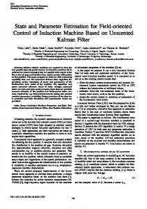
In Fig.1. is shown the block-diagram of studied system. The asynchronous motor is powered by a frequency converter with DC link consisting of three-phase uncontrolled rectifier, the DC braking chooper side and three-phase IGBT inverter. For control of the inverter is used two separated regulation channels: - q channel – PI- regulator in combination with adaptive scalar stabilizer and d – channel – PI - regulator. The output signal from q channel is proportional to motor torque of present induction motor and the output of d-channel – to flux.
where: a t = [a1 , a 2 ,..., a n ] ; I n - 1 - identity matrix with dimensions (n-1)x(n-1); 0 – zero vector with dimensions (n-1)x1. For the equations (1) and (2) describing the investigated system corresponds to following “input/output” difference equations: y (k+n )- a n y (k+n-1)-.... - a 2 y (k+1)- a1 y (k )=
3 Algorithm for Adaptive Control The basic function of the adaptive control is continuously identifying a control object in real time by linear model from low order and creation of control signal. In studied system is used a scalar modal adaptive stabilizer. On the inputs of adaptive stabilizer is feeding discrete sample from measured speed of AC motor and reference speed given from operator. The scalar adaptive modal regulator identifies in real time control object on the basis of estimated parameters and variables of the model and
ISBN: 978-1-61804-128-9
(2)
= h1 u (k + n − 1)+ ... + h n-1 u (k + 1)+ h n u (k ) k = 0,1,2,... (5) The input/output data are shaped in following matrices and vectors.
14
Advances in Power and Energy Systems
Y 1t = [ y (0 ), y (1),..., y (n − 1)];
Y t2 = [ y (n ), y (n + 1),..., y (2n − 1)];
−1 H 1 = − N 1−1 .Y22 .Y12 −1 −1 −1 H 2 = Y12 + Y12 .U 21 .N 1−1 .Y22 .Y12 −1 H 3 = −Y12 .U 21 .N 1−1
(6)
Y t3 = [ y (2n ), y (2n + 1),..., y (3n − 1)];
−1 N 1 = U 31 − Y22 .Y12 .U 21 The Toeplitz matrix T with dimension nxn is shaped. 0 0⎤ L 0 ⎡ 1 ⎢ − 1 L 0 0 ⎥⎥ ⎢ aˆ n T = ⎢− aˆ n − 1 − aˆ n L 0 (8) 0⎥ . ⎢ ⎥ M O M M⎥ ⎢ M ⎢ − aˆ 2 − aˆ 3 L − aˆ n 1⎥ ⎣ ⎦ ˆ The vector estimate b is calculated by linear system equations of following type: T.bˆ = hˆ . (9) The initial vector estimate xˆ (0 ) is calculated by the optimal estimator of following type: xˆ (0) = Y 1 − U 11 .bˆ ; (10) where: xˆ 1 (0) = y (0) . The current vector is estimated by the degenerate optimal singular adaptive observer of the following form : xˆ (k + 1) = Aˆ .xˆ (k ) + bˆ.u(k ), xˆ (0 ) = xˆ 0 , (11) k=0, 1, 2, … , The investigations shown that the controlled system can be identified by model from second order i.e. n = 2 ) Tref ( p ) = − aˆ1 . xˆ1 ( p ) − aˆ 2 . xˆ 2 ( p ) (12)
0 0⎤ L 0 ⎡ 0 ⎢ u (0 ) 0 0 ⎥⎥ L 0 ⎢ u (0 ) L 0 0⎥ ; U 11 = ⎢ u (1) ⎢ ⎥ M O M M⎥ ⎢ M ⎢⎣u (n-2 ) u (n-3 ) L u (0 ) 0 ⎥⎦ u (0 ) ⎤ ⎡ u (n − 1) u (n − 2 ) L ⎢ u (n ) u (n − 1) L u (1) ⎥⎥ ⎢ L u (2 ) ⎥ ; u (n ) U 21 = ⎢ u (n + 1) ⎥ ⎢ M M O M ⎥ ⎢ ⎢⎣u (2n − 2 ) u (2n − 3 ) L u (n − 1)⎥⎦ u (n ) ⎤ ⎡ u (2n − 1) u (2n − 2 ) L ⎢ u (2n ) u (2n − 1) L u (n+1) ⎥⎥ ⎢ u (2n ) L u (n+2 ) ⎥ ; U 31 = ⎢ u (2n + 1) ⎥ ⎢ M M O M ⎥ ⎢ ⎢⎣u (3n − 2 ) u (3n − 3 ) L u (2n − 1)⎥⎦ where U11, U21, U31 are Toeplitz matrices with dimensions nxn; ⎡ y (0 ) y (1) L y (n-1) ⎤ ⎢ y (1) y (2 ) L y (n ) ⎥⎥ ⎢ Y 12 = ⎢ y (2 ) y (3 ) L y (n+1) ⎥ ; ⎥ ⎢ M O M ⎥ ⎢ M ⎢⎣ y (n-1) y (n ) L y (2n-2 )⎥⎦
y (n+1) L y (2n-1) ⎤ ⎡ y (n ) ⎢ y (n+1) y (n+2) L y (2n ) ⎥ ⎥ ⎢ ⎥; ⎢ = ( ) ( ) ( ) L 2 3 2 1 y n+ y n+ y n+ Y 22 ⎥ ⎢ M O M ⎥ ⎢ M ⎢⎣ y (2n-1) y (2n ) L y (3n-2 ) ⎥⎦ where Y12 и Y22 are Hankel matrices with dimensions nxn; The vectors estimations hˆ и aˆ of difference equations (5) are calculated through the following vector-matrix expression: ) ⎡h ⎤ ⎡ H 1 N −1 ⎤ ⎡Y 2 ⎤ 1 ⎥. (7) ⎢ )⎥ = ⎢ ⎢ ⎥ ⎣a ⎦ ⎣⎢ H 2 H 3 ⎦⎥ ⎣Y 3 ⎦ where:
ISBN: 978-1-61804-128-9
where: p=k,k+1,…,k+n.
4 Experimental Results By using the created mathematical model of adaptive control system and computer model was developed in Matlab space. To prove the effective operation of adaptive FOC have been investigated a number of transients processes - changes in the speed reference, modify the moment of resistance of the motor shaft as part of the obtained experimental results are shown below. On figures 2÷7 is shown transient process at variation of motor speed set point. Firstly the motor is starting in idle. In 1sec. is applied constant torque in motor shaft. During variation of speed the applied torque remain constant. On figures 8÷13 is shown transient process at loading of induction motor at constant speed set point.
15
Advances in Power and Energy Systems
ωIM [rev/min]
UDC [V]
1600
720
1400
700
1200
680
1000
660 640
800
620
600
600 400
580 200
560 0
540
-200
520 1
2
3 time [sec]
4
5
6
1
Fig.2. Variation of motor speed at constant torque TIM, Tref [N.m]
2
3 time [sec]
4
5
Fig.5. DC link voltage PIM x10 [kW] 12
1400 1200
10
1000 8
800 600
6
400 4
200 2
0 -200 -400
IIM
0
1
2
3 time [sec]
4
5
1
6
2
3 time [sec]
4
5
Fig.6. Active power of induction motor
Fig.3. Variation of motor torque – red line; Tref – blue line [A]
4 QIM x10 [kVAr] x 10
1
900 800
0
700 -1
600 500
-2
400 -3
300 -4
200 100
-5
0 -6
-100 1
2
3 time [sec]
4
5
-7
6
Fig.4. Variation of motor current. ISBN: 978-1-61804-128-9
1
2
3 time [sec]
4
5
Fig.7. Reactive power of induction motor 16
6
Advances in Power and Energy Systems
ωIM [rev/min]
UDC [V]
1201
720 700
1200 680 660
1199
640
1198
620 600
1197 580 560
1196
540
1195
2
2.5
3
3.5
2
time [sec]
Fig.8. Motor speed: reference speed – red line; motor speed – blue line
2.5 3 time [sec]
3.5
Fig.11. DC link voltage.
TIM [N.m]
PIM x10 [kW]
2500 14
2000
12
1500
10
1000
8
500
6
0
4
-500
2 0
-1000 2
2.5
3 time [sec]
3.5
2
2.5
3
3.5
time [sec]
Fig.12. Active power of induction motor
Fig.9. Variation of motor torque – red line; Tref – blue line
QIM x10 [kVAr]
IIM [A] 1000
0
900 800
-2
700 600
-4
500 400
-6
300 -8
200 100
-10
0 2
2.5
3
2
3.5
time [sec]
3 time [sec]
3.5
Fig.13. Reactive power of induction motor
Fig.10. Variation of motor current. ISBN: 978-1-61804-128-9
2.5
17
Advances in Power and Energy Systems
a Fuzzy Logic Controller Based on an Indirect Vector Control for Induction Motor Drive, Journal of Electrical Engineering, Vol.55, No.7-8, 2004, pp.188-194. [8] Denai M.A., Attia S.A., Fuzzy and Neural Control of an Induction Motor., Int. J. Appl. Math. Comput. Sci., 2002, Vol.12, No.2, pp.221–233. [9] Sotirov L. N., Selected chapters from modern control theory, Technical university of Varna, Bulgaria,1998, 281 pp.
6 Conclusion The proposed new adaptive stabilizer for speed control of AC drives allows optimizing all parameters of electrical drive in dynamic regimes. Thanks to the identification of the controlled object using a linear model of low order the required calculation time is much less than the rate of change of the status of the electrical drive. This control can be realized using modern signal processors (DSP). The studies of the proposed adaptive control in Matlab space show very good performance, efficiency and effectiveness of the proposed adaptive controller. Application: 3-phase AC motor parameters: P=150kW, U=460V, f=60Hz, Rs=14,8.10-3Ω, Ls=0,3.10-3H, Rr=9,3.10-3 Ω, Lr=0,3.10-3H, Lmutual=10,5.10-3, J=3,1kg.m2, Friction=0,08Nms, Pole pairs=2; References: [1] Nandam P. K., Sen, P. C. A Comparative Study of Luenberger Observer and Adaptive Observer-Based Variable Structure Speed Control System Using Self-Controlled Synchronous Motor, IEEE Transactions on Industrial Electronics 37 (1990), 127–132. [2] Utkin, V. I. Sliding Mode Control Design Principles and Applications to Electric Drives, IEEE Transactions on Industrial Electronics 40 (1993), 23–36. [3] Ravitharan N. G., Vilathgamuwa D. M., Duggal, B. R.: Fuzzy Variable Structure Control of Induction Motors with Sag RideThrough Capability, 4th IEEE Power Electronics and Drives Systems, Vol.1, pp. 235–240, 22–25 Oct. 2001. [4] Zhang J., Barton T. H.: Optimal Sliding Mode Control of Asynchronous Machine Speed with State Feedback, in Conf. Rec. IEEE IAS Annual Meeting, pp. 328–336, 1988. [5] El-Kholy E. E. High Performance Induction Motor Drive Based on Adaptive Variable Structure Control, Journal of Electrical Engineering, Vol.56, No.3-4, 2005, pp.64–70. [6] Wang J. B. and Liaw C. M., Indirect Fieldoriented Induction Motor Drive with Fuzzy Detuning Correction and Efficiency Optimization Controls, IEE Proc.-Electrical Power Applications, Vol.144, No.1, pp.37-45. 1997. [7] Mokrani L., Kouzi K. Influence of Fuzzy Adapted Scaling Factors on the Performance of
ISBN: 978-1-61804-128-9
18