Hindawi Publishing Corporation International Journal of Reconfigurable Computing Volume 2013, Article ID 517947, 12 pages http://dx.doi.org/10.1155/2013/517947
Research Article An Asynchronous FPGA Block with Its Tech-Mapping Algorithm Dedicated to Security Applications Taha Beyrouthy and Laurent Fesquet Laboratoire TIMA, 46 Avenue F´elix Viallet, 38031 Grenoble, France Correspondence should be addressed to Taha Beyrouthy;
[email protected] Received 6 September 2012; Revised 26 November 2012; Accepted 9 December 2012 Academic Editor: Michael H¨ubner Copyright © 2013 T. Beyrouthy and L. Fesquet. This is an open access article distributed under the Creative Commons Attribution License, which permits unrestricted use, distribution, and reproduction in any medium, provided the original work is properly cited. This paper presents an FPGA tech-mapping algorithm dedicated to security applications. The objective is to implement—on a full-custom asynchronous FPGA—secured functions that need to be robust against side-channel attacks (SCAs). The paper briefly describes the architecture of this FPGA that has been designed and prototyped in CMOS 65 nm to target various styles of asynchronous logic including 2-phase and 4-phase communication protocols and 1-of-n data encoding. This programmable architecture is designed to be electrically balanced in order to fit the security requirements. It allows fair comparisons between different styles of asynchronous implementations. In order to illustrate the FPGA flexibility and security, a case study has been implemented in 2-phase and 4-phase Quasi-Delay-Insensitive (QDI) logic.
1. Introduction During the last decade, FPGA manufacturers have successfully reached a high level of performance in their designs. Nowadays, FPGAs are not only used as fast prototyping tools, but they also become active players as components in embedded systems [1]. Moreover, the increasing attractiveness of embedded systems has made them part of our everyday life, especially when it comes to security applications, where cryptographic algorithms and countermeasures need to be updated or changed in some cases, for instance in homeland security, e-banking, and pay-tv. Thus, it becomes very important to guarantee a high level of flexibility and security for these FPGAs, in order to make them robust against different forms of attacks which aim to illegally retrieve secret information hidden in cryptographic systems. Unlike cryptography that protects confidentiality, integrity, or secure authentication, the cryptanalysis is about the challenge to retrieve hidden information. There are no known mathematical cryptanalysis methods which can decrypt standard cryptographic algorithms like AES in a reasonable amount of time and space, assuming that the cryptanalyst has access to both plain text and encrypted
messages. However, such algorithms are implemented with some physical processes that leak information. An access to this physical information makes the job of the cryptanalyst much easier. These kinds of leakage from physical processes are commonly known as side-channel leakage. Physical cryptanalysis has been demonstrated to be effective against various standard algorithms and on various platforms in recent times (FPGAs, ASICs, etc.). Researchers have shown that side-channel attacks can be mounted on standard cryptographic algorithms like DES [2], AES [3] and RSA [2]. A widely known SCA is DPA (differential power analysis) [4], which exists in various forms [5] and concerns the information leaked through supply current peaks. Attacks which exploit the electromagnetic emissions (EMA) [6] from the hardware constitute another major branch of sidechannel attacks. The attacks on RSA, which use the difference in execution time, as their major source of information, have also been reported, and this is commonly known as timing attacks [2]. These attacks put in danger critical applications such as banking. Credit cards use algorithms similar to RSA for authentication, and 2-key triple DES for the challenge [7].
2 Wholesale frauds on systems which rely on smart cards for their security (e.g., pay-tv) could also be a target of such attacks. Mounting a side-channel attack requires expertise and expensive high-resolution equipment. So such techniques are prone to be used only if there is enough gain. Contrarily, the unprotected devices—which require cheap equipment—will be an easy target for such attacks. One more reason to incorporate side-channel resistance into these systems. On the other hand, asynchronous circuits are more and more used in order to remove the clock distribution problems and to reduce the power consumption overhead, which drastically increases with frequency. Furthermore, because of their weak sensitivity to SCAs, asynchronous circuits appear to be an interesting alternative to their synchronous counterparts for implementing cryptosystems [8, 9]. Therefore, an asynchronous secured FPGA could be of interest. To the best of our knowledge, today there is no FPGA natively secured against SCAs attacks. In the literature, several architectures of programmable asynchronous circuits have been proposed [10–14]. They often use the properties of asynchronous logic for high performance (high speed, low power, robustness, etc.). From the flexibility point of view, most of them are dedicated either to a specific asynchronous circuit style (PGA-STC [15], PAPA [16]), or to a dedicated application (MONTAGE [17], GALSA [18], STACC [19], and Speedster [20] FPGAs). For examples, PGA-STC was developed to implement twophase bundled-data systems such as micropipelines, GALSA for massively parallel computing architectures, STACC for reconfigurable computation, PAPA for fine-grain pipelines with a high throughput, and Speedster from Achronix is now the world’s fastest FPGA. From the security point of view, all these FPGAs are vulnerable to differential power analyses “DPAs” and more generally to SCAs attacks. In spite of this situation, very few research works address the FPGA security. Our project called S.A.F.E. (Secure Asynchronous FPGA for Embedded Systems) aims at specifying, designing, and validating an asynchronous programmable circuit (FPGA) suitable for flexible, high-performance, and secured implementations. We propose a novel FPGA architecture [21] that is natively robust against differential power analysis (DPA), simple power analysis (SPA), and timing attacks. It has also been designed to be more flexible than the existing asynchronous programmable circuits. To achieve such a level of robustness, all security problems have been addressed at all the abstraction levels: architectural, logical, electrical and physical. In order to meet the security requirements, a specific tech-mapping algorithm has been developed and is presented in the sequel (the routing technique was presented in [22]). The paper is organized as follows: Section 2 outlines the FPGA security features. Section 3 describes the FPGA architecture. Section 4 presents the technology-mapping algorithm. Finally, the last part gives some test results of a 2-phase and 4-phase SBOX (substitution box) implementation on our asynchronous FPGA, as well as an implementation of the same function on a standard unsecured FPGA.
International Journal of Reconfigurable Computing
2. Secured Asynchronous FPGA Specifications The FPGA reconfigurability can offer major advantages for cryptographic applications [9]. However, the physical implementation of FPGAs might provide side channels that leak critical information, for instance, power consumption, timing behavior, electromagnetic emission, and surface temperature. These different types of side-channels are considered as information sources that can be used potentially by attackers to reveal the secret key of a cryptographic algorithm. Simple power analysis (SPA) and differential power analysis (DPA) have been introduced in [23]. While performing a ciphering operation, the power consumption of cryptographic devices is analyzed in order to extract the secret cipher keys. These attacks exploit the datadependent power consumption of the cryptographic device. In [24], the author proves that electromagnetic analysis (EMA) is more efficient than DPA. It uses the electromagnetic fields emitted by the switching gates as side-channel information. Fault attacks (FAs) presented in [25] are also an efficient type of attacks. With these kinds of attacks, an attacker injects faults into the device while it executes a known program. In this case, the device behavior can reveal the secret information to the hacker. Many countermeasures have been recently implemented in ASICs to prevent SPA, DPA, EMA, and FAs. One interesting approach consists in using balanced Quasi-DelayInsensitive (QDI) asynchronous circuits [26] as a countermeasure. This approach appears to be one of the most promising. This work aims at transposing this method in an FPGA context. The challenge is first to make the asynchronous FPGA natively robust against SPA and DPA while being very flexible. Afterwards, countermeasures against other SCAs and FAs can be easily explored and experimented. The FPGA presented in this paper offers the following advantages towards security issues. (i) Balanced Power Consumption. QDI circuits that generally use 1-of-𝑛 encoding (e.g., dual-rail, triple-rail, e.g.) can be balanced to reduce the power consumption dependency with the processed data. Indeed, the bit encoding ensures that the data are transmitted and the computations are performed with a constant Hamming weight. This is important since the leakage of the Hamming weight or distance can be exploited by SPA, DPA, and EMA. In addition, the Hamming weight constant technique can be combined with other countermeasures. For instance, in [8], the authors propose to use a temporal or a spatial jitter to make power consumption more unintelligible. (ii) No Global Synchronization Signal. The absence of the clock signal means that FAs based on clock are no more possible to perform. Moreover, DPA and SPA attacks are expected to be much more difficult without global clock signal. Indeed, the clock absence will make the synchronization of the DPA and SPA signatures very complicated. (iii) Tolerance to Environment Variations. QDI circuits are robust to the environment variations, such as voltage and
International Journal of Reconfigurable Computing
3
PLB
PLB Connection box
PLB
PLB
Switch box
Figure 2: FPGA architecture. Figure 1: Asynchronous FPGA layout.
temperature variations. Therefore, they are tolerant to many kinds of fault injection (power glitches, thermal gradients, etc.). These QDI circuits can also be combined with other countermeasures to efficiently counteract FAs [27]. (iv) Redundant Data Encoding. QDI circuits typically use a redundant data-encoding scheme (1-of-𝑛 data encoding). For instance, the dual-rail encoding (a bit is encoded onto two wires) provides a mean to encode an alarm signal to counteract FAs [26]. (v) Balanced Implementation. As it is presented in the sequel, the tech-mapping algorithm, which was developed especially for this FPGA, allows implementing secured functions while keeping their architecture electrically and logically balanced. This helps increasing the security of the circuit by making the power consumption and the computation time more dataindependent.
3. The A-FPGA Architecture This section gives an overview of the proposed asynchronous FPGA architecture [21]. Figure 1 shows the layout of the A-FPGA prototype, designed in 65 nm, and fabricated by STMicroelectronics. It is a full-custom layout, designed to be electrically balanced in order to fit the security constraints. As far as we know, it is probably the world first secured asynchronous FPGA. 3.1. General Description of the FPGA Architecture. The global architecture of the FPGA is an island-style architecture mainly composed by Programmable Logic Blocks (PLBs). Like a classical FPGA, it contains a programmable interconnect network whose the building blocks are connection boxes (CBs) and switch boxes (SBs). The interconnect network was fully described in a previous paper [22]. Finally, the FPGA architecture is the repetition in 2-dimension of the pattern made by a PLBs, 2 connection boxes, and a switch box as described in Figure 2. 3.1.1. The Programmable Logic Block (PLB). The PLB architecture has been designed to be a good trade-off between the efficient resource management and the high flexibility required to be style-independent (many asynchronous logic
styles exist: 4-phase, 2-phase logic, e.g., and different data encoding: for instance the 1-of-𝑛 data encoding). Figure 3 shows the details of the PLB architecture. Each PLB has 12 inputs and 7 outputs. It consists of two logic elements (LE), one LUT2-1, one XOR, and three multiplexers. Its outputs are directly connected to the connection boxes. 3.1.2. The Logic Element (LE). The Logic Element is a programmable logic component that hosts the function generators. It has 6 inputs, and 4 outputs, and consists of two LUT6-1 [28, 29], followed by a multiplexer and one XOR, connected together as shown in Figure 5. For more flexibility, inside the LE, each input is connected to a multiplexer M𝑘 In𝑙 Out𝑚 (M𝑘 In𝑙 Out𝑚 : means the multiplexer “𝑘” (M𝑘 ) is connected to the first “𝑙” input (In𝑙 ) and contributes in computing the output “𝑚” (Out𝑚 )) that allows a programmable choice between 2 types of inputs: (i) the first is for primary input (In𝑗 with 𝑗 = 0, 1, 2, 3, 4, 5) connected to external signals; (ii) the second is for feedback, where internal signals— which are some of the PLB outputs Out𝑖 with 𝑖 = 0, 1, 3, 4, 5—are looped back to the multiplexer’s inputs (see Figure 5). As shown in Figure 5, the LE outputs are fed back to the LE inputs through multiplexers in order to ensure the implementation of memory elements that are commonly used in asynchronous logic such as Muller 𝐶-elements. This implementation technique was first presented in [30]. The Muller gate is in fact a state-holding element (see Figure 4). When all inputs are set to the same value, the output is set to the inputs value. When the inputs are different, the output does not change as shown in the table in Figure 4. Consequently, when the output changes from 0 to 1, we may conclude that both inputs are 1. And similarly, when the output changes from 1 to 0, we may conclude that both inputs are set to 0. This behavior could be interpreted as an acknowledgement that indicates when both inputs are 1 or 0. This is why the Muller element (or 𝐶-element) is extensively used in asynchronous logic and is considered as the fundamental component on which is based the 4-phase and 2-phase asynchronous protocols implementation. The LE feedbacks in Figure 5 also give much more flexibility to the LE to implement complex functions.
4
International Journal of Reconfigurable Computing In1
In2
In3
In4
In0 In1 In2 In3 In4 In5
In5
Out7
Logic Element II
Out6
Out2
Logic Element I
LUT2
Out9
Out8 P2
P1 Out0 Out1 Out2 /Out6
Out5
In0
PLB
P3
Out8 /Out9
Out5 /Out7 Out3 Out4
Figure 3: PLB architecture. I1
I2
Out
0 0 1 1
0 1 0 1
0 Out−1 Out−1 1
I1
C
Out
I2
Figure 4: Muller 𝐶-element.
To ensure such a behavior, each multiplexer connected to the LUT6-1 inputs is controlled by a programmable selection bit 𝑆𝑘 : if 𝑆𝑘 is set to 1, memorization is enabled, and thus one of the PLB outputs will become one of the PLB inputs. Otherwise (𝑆𝑘 set to 0), primary inputs are used, and so external signals are connected to the LE inputs. Thus, each LE can implement a 6-input logical function, which is almost the equivalent of an asynchronous 2-input dual-rail gate (2 rails for each input + one acknowledgement signal + one feedback signal for the memorization) (see Figure 6). Implementing a 3-input dual-rail gate requires the two LEs of the PLB (Figure 7). Output rails will be mapped onto the outputs of each LE. The multiplexer of the output “Out2 ” is connected to Out0 and Out1 of the corresponding LUT6-1 (see Figure 5). This output (Out2 ) is fed back to the multiplexer selection bit. Thus, a memorization is always implemented on Out2 : Out2 = 𝑓 (Out0 , Out1 , Out2 −1 ) = 𝑓 (𝐴 0 , 𝐴 1 , 𝐵0 , 𝐵1 , 𝐶0 , 𝐶1 , Out2 −1 ) , Out5 = 𝑓 (Out3 , Out4 , Out5 −1 )
(1)
= 𝑓 (𝐴 0 , 𝐴 1 , 𝐵0 , 𝐵1 , 𝐶0 , 𝐶1 , Out5 −1 ) . As multiple outputs are available per LE, 1-of-𝑛 encoding (especially dual-rail) can easily be implemented. In addition,
implementing multirail encoding is also quite simple with a reduced number of LEs, thanks to their large number of inputs. Using the 1-of-𝑛 encoding—which is a balanced data encoding—in association with the balanced FPGA architecture enhances the security characteristics of the FPGA and makes DPA attacks more difficult [31]. With this encoding style, both logical “0” and logical “1” are encoded with code words of the same Hamming weight, “01” and “10,” respectively. If an electrical symmetry is considered in the whole design, along such an encoding style, power consumption is expected to be quasi-data-independent. Figure 5 shows the fully balanced architecture of the Logic element block “LE.” (i) The Look Up Table 6-1 (LUT6-1). The following equation shows that an LUT6-1 is able to implement, a 6-input function: Out0 = 𝑓1 (In0 | Out0 , In1 | Out1 , In2 | Out3 , In3 | Out4 , In4 | Out5 , In5 | Out0 ) .
(2)
It is important to notice that the feedback usage allows the following. Memorization. In this case, the internal feedback is used. The LUTs are able to implement functions with memorization which are required for asynchronous logic. For example, in case of the LUT6-1 on the left of Figure 5, the internal feedbacks are Out0 and Out1 . Cascading Functions. These feedbacks allow the mapping of multirail and complex functions (more than 6 inputs). The four external feedbacks help to split complex functions into smaller ones (≤6 inputs) and to cascade them in the same PLB. Thus, no resource is taken from the interconnection network. For instance, in Figure 5 the external feedbacks of the LUT6-1 on the left of the PLB are Out3 , Out4 , and Out5 .
International Journal of Reconfigurable Computing In0
Out0
In1
Out1
In2
In3
Out3
In4
Out4
5 In5
Out5 Out0
Out0
Out1
Out3
LUT6-1
Out4
Out5
Out1
LUT6-1
Out2
Out0
Out6
Out1
Figure 5: Logic Element architecture.
A0 A1 B0
B1 Ack Out 0−1
A0 A1 B0
B1 Ack Out1−1
A0
A1
B0
B1 C0 C1
A0
LE
LUT6-1
B0
B1 C0 C1
LE
LUT6-1
Out2 Out0
A1
Out6 = Ack out
Out1
Out8 = Ack out
Out5
Figure 7: 3-input dual-rail gate implementation.
Figure 6: 2-input dual-rail gate implementation.
(ii) The LUT2-1 and the XORs. Asynchronous logic requires implementing protocols between communicating modules, which basically consists in computing an acknowledgment signal. Inside the Logic Element, this protocol is supported by adding an XOR directly connected to the outputs of both
LUT6-1 (see the Out6 in Figure 5). This allows to check the data validity on both Out0 and Out1 , and to provide an acknowledgement. Outside the Logic Element, the LUT2-1 and the XOR ensure the same role (Out8 and Out9 ) (cf. Figure 3). As Out2 and Out6 are never used simultaneously, we connected them to a multiplexer whose selection input is
6
International Journal of Reconfigurable Computing
a programmable bit (𝑃1 ) (cf. Figure 3). The same thing is done with the outputs Out7 /Out5 and Out8 /Out9 . As a result, the number of PLB’s outputs is decreased and the interconnection complexity is reduced.
use 2 LUT6-1s of the same LE to implement each function. If 𝑛 = 7 then use 2 LEs of the same PLB to implement each of
4. The Technology-Mapping Algorithm 4.1. Introduction. The FPGA is a reconfigurable integrated circuit that consists of a PLBs matrix with vertical and horizontal programmable routing networks. The PLBs are based on two LUT6-1 (6-input LUTs). Each one contains 26 truth table configuration bits and allows the implementation of a 6-input function. On the one hand, the number of PLBs needed to implement a given circuit determines the size and cost of the FPGA. On the other hand, its security depends on the symmetry of the whole PLBs network. Therefore, one of the most important phases of the FPGA design flow is the technologymapping step which maps the optimized circuit description onto the PLBs network. Two main objectives were defined for the mapping algorithm. Area Efficiency. The implementation of a function should minimize the PLB’s resources. In fact, if the considered function has maximum 6 primary inputs, it will be mapped into one PLB, which means no optimization job is needed in this case. But if it has more than 6 primary inputs, a specific mapping method will be used as we will see later on. Security. The implemented circuit is balanced at the architectural level. The technology mapping algorithm allows keeping the symmetry and generates “balanced function.” As a result, the implementation will be electrically balanced—thanks to the FPGA secured design—and logically balanced—due to the implementation symmetry. Thus, in a logical cone, each input propagates from input to output through the same number of blocks. 4.2. The Mapping Algorithm. This section concisely describes the mapping algorithm used to implement different asynchronous functions onto the FPGA presented above. Both 4phase and 2-phase Quasi-Delay-Insensitive (QDI) logic have been tested. The 1-of-𝑛 data encoding has been used only with the 4-phase structure. For a given dual-rail function “𝑓”, Out0 and Out1 are the outputs representing the bit values “0” and “1,” respectively. The algorithm is given in the following. For functions Out0 and Out1 Begin
them. (It’s worth noting that the feedback of each function is in this case ensured by the multiplexer connected to the outputs of both LUT6-1 of the LE (see Figure 5)). If 7 < 𝑛 If 2-phase case then do method for more than 7 2-phase Eslif 4-phase case then do method for more than 7 4-phase End. The difference between the method for more than 7 2phase and the method for more than 7 4-phase is the way they manage the implementation of the communication protocol. These methods are described as follows. Method for More Than 7 2-Phase & 4-Phase. Before presenting these methods, it is important to take into consideration the following points. (1) The LE does not support more than 7-input functions (cf. Figure 5). Thus, a function with more than 7 inputs should be split into smaller subfunctions (inputs ≤ 7), in order to map each of them in different LEs. (2) The result of this decomposition could be vulnerable against side-channel attacks because the final circuit is not guaranteed to be electrically or logically balanced. (3) It is possible to make the above decomposition robust against side-channel attacks, by adding countermeasures that balanced the circuit on the logically and the electrically level. These countermeasures will mostly be implemented at the structural level (netlist), and thus will lead to increase the number of PLBs used for mapping the circuit. As a result, these so-called “method for more than 7 2phase” and “method for more than 7 4-phase” are developed for securely mapping functions with more than 7 inputs and minimizing as much as possible the number of PLBs. They are based on separating the communication protocol part from the computation part of the function. It is defined by 2 main steps:
Compute the number 𝑛 of single inputs of both functions.
(i) the first step consists in computing the output without considering the communication protocol.
(It must be the same because both of them belong to the same dual rail function. The number 𝑛 is representing the number of inputs including the feedback.
(ii) The second step adds the communication protocol to the circuit. At this structural level, the circuit works normally and is electrically and logically balanced.
ex: if Out0 = 𝑌(𝑎0 , 𝑎1 , 𝑏0 , 𝑏1 , 𝑐0 , 𝑐1 , Out0 −1 ), then 𝑛 = 7, where Out0 −1 is the feedback.) If 𝑛 ≤ 6 then
It is worth mentioning that countermeasures are added within these two steps in order to balance the circuit on the logically and the electrically levels.
International Journal of Reconfigurable Computing
7
6 Secret key XOR
6
SBOX2
4
Plaintext 6
State
d1
d0
Valid “0”
0
1
Valid “1”
1
0
Invalid
0
0
Not used
1
1
Figure 8: Sensitive submodule of the DES.
These methods have been validated, as presented later in this paper. They allowed us to make a comparison between 2-phase and 4-phase circuits, and their behavior towards security constraints.
01 “1”
00 Invalid
10
“0”
Figure 9: Three-state encoding.
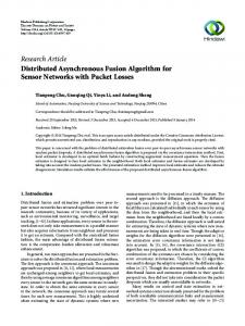
5. Experimental Results 5.1. Mapping a Dual-Rail-Sensitive DES Submodule Using 4Phase and 2-Phase Communication Protocols. In this section, a submodule of the DES [32] (Data Encryption Standard) algorithm is studied: an XOR followed by the substitution box (SBOX) (see Figure 8). As shown in Figure 8, this module has two main jobs: the first is the combination of the plaintext with the secret key which is done by a 6 dual-rail input XOR; the second encodes its outputs using a substitution function: the S-BOX. Many studies have proved that this block is very sensitive to side-channel attacks. Thus, it is important to ensure a high level of security on it [33]; otherwise a hacker could easily retrieve—through a power analysis—the secret key used during the encryption. This submodule is implemented on the FPGA using our dedicated tech-mapping algorithm. Both 4-phase and 2phase protocols are evaluated and compared. Then a quick comparison of these results with those of a standard FPGA is made to prove the efficiency of our countermeasures approach. 5.1.1. Implementation Using Dual Rail 4-Phase Protocol. The 4-phase dual-rail protocol uses two wires 𝑑0 and 𝑑1 per bit to encode data. The first 𝑑1 is used for signaling logic 1, and the second 𝑑0 is used for signaling logic 0. The couple {𝑑0 , 𝑑1 } could have 3 different combinations: (i) {0, 1} to present logic 1 → Valid Data; (ii) {1, 0} to present logic 0 → Valid Data; (iii) {0, 0} to present no data → Invalid Data; (iv) {1, 1} this couple is not used. Also, in the 4-phase protocol, the transition between a valid state and another valid state is not allowed. Between two valid states, an invalid state must occur as shown in Figure 9. This encoding is known as the three-state-data-encoding. The term 4-phase refers to the number of communication actions in a complete communication cycle. This protocol is familiar to most designers. It is in fact very robust because two blocks can communicate reliably regardless of delays in the wires; it is a delay-Insensitive protocol. However, the superfluous return-to-zero transitions create an
unnecessary waste of time. One of its most important features is that this data encoding has a constant hamming weight. It is important because, as described in Section 2, the leakage of the Hamming weight or distance can be exploited by SPA, DPA, and EMA. As shown in Figure 8, the XOR of the submodule is a function that has 6 dual-rail inputs and six dual-rail outputs. However, outputs are given by computing the XOR of the inputs bit per bit. Thus, the XOR is implemented on 12-LUTs (3 PLBs). The SBOX implementation is more complicated than the XOR’s one. In fact, with a 4-phase dual-rail protocol, each SBOX output is a dual-rail function represented by two wires 𝑂1 and 𝑂0 . We denote, respectively, 𝑓0 (𝐴 0 , 𝐴 1 , 𝐵0 , 𝐵1 , 𝐶0 , 𝐶1 , 𝐷0 , 𝐷1 , 𝐸0 , 𝐸1 , 𝐹0 , 𝐹1 ) , 𝑓1 (𝐴 0 , 𝐴 1 , 𝐵0 , 𝐵1 , 𝐶0 , 𝐶1 , 𝐷0 , 𝐷1 , 𝐸0 , 𝐸1 , 𝐹0 , 𝐹1 ) ,
(3)
the functions computing the values of each wire. 𝑂1 and 𝑂0 equations could be written as follows: 𝑓1 𝑂1 −1
if all inputs are valid and Ackin = 0 otherwise
𝑓 𝑂0 = { 0 −1 𝑂0
if all inputs are valid and Ackin = 0 otherwise.
𝑂1 = {
(4)
Each equation needs 6 dual-rail inputs, an Ackin signal, and a feedback. They are considered as a 14 inputs-functions. Thus the method for more than 7 4-phase is used to implement them on the FPGA. The resulting circuit is implemented on 8 PLBs where 6 PLBS are needed for the communication protocol and two others for the outputs computation. The acknowledgement signal Ackout of each dual-rail output is computed using the LUT2 of the PLB that does the computation of the final stage of this output. So no extra PLBs are used for the acknowledgement (see Figure 3). In order to evaluate the area efficiency of the block implementation, a filling ratio has been calculated. The filling ratio of the LEs is defined as the number of the used primary inputs over the total number of primary inputs. Figure 5 shows that a Logic Element (LE) has a total of 6 primary
International Journal of Reconfigurable Computing 1.4
2 0 −2 −4 −6 −8 −10 −12 −14
1.2 1 0.8 V
e−3 A
8
0
1
2
3
4
e −9 s
Figure 10: Current profiles of the DES submodule block implemented on the secure FPGA.
inputs (In0 , In1 , In2 , In3 , In4 , and In5 ). Thus, the overall filling ratio of this submodule is 88%. It is a metric we used that help us to know how far Logic elements are used and thus evaluating the area efficiency of the PLBs. To meet the security constraints presented in Section 2: (i) the subblocks of this function are implemented using a 1-of-𝑛 encoding. This strategy guarantees a constant Hamming weight which is required to make power consumption data-independent. (ii) The circuit architecture is fully symmetric. This means that all the data paths have the same logical depth. To validate the implementation native-robustness against SPA, DPA, and timing attack, an electrical simulation campaign has been carried out. The analyzed block (cf. Figure 8) has been designed in an CMOS 65 nm technology. Remind that, to be robust against DPA, SPA, and timing attack the block should have the same current profiles and a constant running time whatever the manipulated data. During the electrical simulation campaign and for a given secret key, random plain-text vectors have been processed. The corresponding current profiles are given in Figure 10 and the outputs are given in Figure 11. Figure 10 shows that all current profiles curves of the circuit are overlapped. That means that whatever the manipulated data are, the current profiles are very similar. In other words, the power consumption is quasi-data-independent. In addition, as shown in Figure 11, the outputs curves are also superposed. This means that the FPGA running time is also quasi-data-independent. This drastically increases the circuit robustness against SCAs exploiting the running time variations. In conclusion, with a quasi-data-independent power consumption and a constant running time, this implementation could be considered as natively robust against SPA, DPA, and timing attacks. 5.1.2. Implementation Using Dual-Rail 2-Phase Protocol. The 2-phase dual-rail protocol has a minimal sequence of data exchange. It uses 2 wires {𝑑0 , 𝑑1 } per bit. But the difference between the 2-phase and the 4-phase protocols is that the information in 2-phase protocol is encoded as transitions (events). There is no difference between a 0 → 1 and a 1 → 0 transition. In fact, both represent new data.
0.6 0.4 0.2 0
0
1
2
3
4
e−9 s
Figure 11: Outputs of the DES submodule block implemented on the secure FPGA.
A new datum is received when an event occurs on exactly one wire of the 2 wires. In this protocol, there is no invalid state, or unused state. Each message is acknowledged and immediately followed by the next message. This encoding is known as the 4-state data encoding (see Figure 12). The term 2-phase refers to the number of communication actions in a complete communication cycle. The 2-phase protocol avoids the superfluous return-tozero phase. Thus, it is faster than the 4-phase. In spite of its efficiency, the asymmetry between phase 1 and phase 2 makes it more difficult for the designer to implement this protocol. Moreover, its data encoding unfortunately provides a variable hamming weight, which is considered as a serious leak of information in side-channel attacks. In order to address this problem, the LUT6-1 inputs were specially designed to balance the hamming weight of input data (see Figure 13). The inverters added on the inputs of the LUT6-1 are designed in order to balance the propagation delay (it is a fullcustom design). Also, they generate for each input data 𝐴, two values 𝐴 and 𝐴 in order to have a data-independent constant hamming weight. The DES submodule (XOR + SBOX) is implemented on the FPGA using 2-phase protocol. The XOR has 6 dualrail input and 6 dual-rail outputs. Its outputs are given by computing the XOR of the inputs bit per bit. Thus, the XOR is implemented on 12 LUTs (3 PLBs). Each of the SBOX outputs is a dual-rail function represented by two wires 𝑂1 and 𝑂0 . We denote, respectively, 𝑓0 (𝐴 0 , 𝐴 1 , 𝐵0 , 𝐵1 , 𝐶0 , 𝐶1 , 𝐷0 , 𝐷1 , 𝐸0 , 𝐸1 , 𝐹0 , 𝐹1 ) , 𝑓1 (𝐴 0 , 𝐴 1 , 𝐵0 , 𝐵1 , 𝐶0 , 𝐶1 , 𝐷0 , 𝐷1 , 𝐸0 , 𝐸1 , 𝐹0 , 𝐹1 ) , the functions computing the values of each wire.
(5)
International Journal of Reconfigurable Computing
9
“0”
A
C
B
D
E
F n=6
00
Complex gate 01
“1”
10
“0”
dec0
Complex gate 11 dec2n−1
“1”
Figure 12: Four-state data encoding. Figure 13: Detailed inputs of the LUT6.
𝑂1 and 𝑂0 equations could be written as follows: if condition 1 & Ackin = 1, if condition 2 & Ackin = 0, otherwise,
𝑓 { { 0 𝑂0 = {𝑓0 { −1 {𝑂0
if condition 1 & Ackin = 1, if condition 2 & Ackin = 0, otherwise.
4
0
(6) −5
e −3 A
𝑓 { { 1 𝑂1 = {𝑓1 { −1 {𝑂1
With
−10
(i) condition 1: 𝐴 0 ⊕ 𝐴 1 = 𝐵0 ⊕ 𝐵1 = 𝐶0 ⊕ 𝐶1 = 𝐷0 ⊕ 𝐷1 = 𝐸0 ⊕ 𝐸1 = 𝐹0 ⊕ 𝐹1 = 0;
(7)
(ii) condition 2: 𝐴 0 ⊕ 𝐴 1 = 𝐵0 ⊕ 𝐵1 = 𝐶0 ⊕ 𝐶1 = 𝐷0 ⊕ 𝐷1 = 𝐸0 ⊕ 𝐸1 = 𝐹0 ⊕ 𝐹1 = 1.
−15
−20
0
(8)
As each equation needs 6 dual-rail inputs, an Ackin signal and a feedback, it is considered as a 14 inputs function. Thus, the method for more than 7 2-phase is used to implement it on the FPGA. The resulting circuit is implemented on 9 PLBs where 7 PLBS are needed to the communication protocol and two others for the outputs computation. The acknowledgement signal Ackout of each dual-rail output is computed using the LUT2 of the PLB that does the computation of the final stage of this output. Thus, no extra PLBs are used (see Figure 3). The overall filling ratio of this submodule is 88%. To meet the security constraints presented in Section 2: (i) although the 2-phase data encoding is not a 1-of-𝑛, we ensured—thanks to the LUT6’s designed inputs—a constant Hamming weight which is required to make power consumption data-independent.
1
2
3
4
e −9 s
Figure 14: Current profiles of Figure 8 DES submodule block implemented on the secure FPGA.
(ii) The circuit architecture is also fully symmetric thanks to the dedicated tech-mapping algorithm. This means that all the data paths have exactly the same logical depth. To validate the implementation native-robustness against SPA, DPA, and timing attacks, an electrical simulation campaign has been carried out. During the electrical simulation campaign and for a given secret key, random plain-text vectors have been processed. The corresponding current profiles are given in Figure 14 and the outputs are given in Figure 15.
10
International Journal of Reconfigurable Computing
e−3 A
1.4 1.2 1
0.2 0 0.2 0.4 0.6 0.8 1 0
0.5
1
1.5
V
0.8
2
2.5
3
3.5
4
e −9 s
0.6
Figure 16: Current profiles of Figure 8 DES submodule block implemented on a standard model FPGA.
0.4 0.2 V
0
0
1
2
3
4
e −9 s
Figure 15: Outputs of the DES submodule block implemented on the secure FPGA.
Figure 14 shows that all current profiles curves of the circuit are overlapped. That means that whatever the manipulated data are, the current profiles are very similar. So the power consumption is quasi-data-independent. In Figure 15, the outputs are also superposed. This means that the FPGA running time is quasi-data-independent. This drastically increases the circuit robustness against SCAs that exploit the running time variations. In conclusion, with dataindependent power consumption and a constant running time, this implementation is natively robust against SPA, DPA, and timing attacks. Comparing these results to those we obtained in 4phase—from the security point of view—both 2-phase and 4-phase implementations are robust against side-channel attacks based on power and timing analysis. The only difference is that the 2-phase protocol is faster than the 4phase as it requires 2 communication actions to complete the communication cycle, while the 4-phase protocol needs 4 actions. The price to pay is one more PLB: 7 PLBs were needed to implement the communication protocol in 2-phase and only 6 PLBs for the 4-phase case. 5.1.3. Implementation of the Block Using 4-Phase on a Standard Model FPGA. Finally, the same block was implemented on a standard model FPGA commonly used in commercial FPGAs. It needs 8 PLBs in order to be implemented with a dualrail 4-phase protocol, using the same algorithm. The same electrical simulation campaign was executed: the corresponding current profiles are given in Figure 16 and the outputs are given in Figure 17. As we can see in Figure 16, current profiles are different. This means that the consumption of the circuit changes when its inputs changes. The DES submodule power consumption is now data-dependent. This dependency makes a DPA attack of this FPGA easy. Figure 17 reflects the different running times of the circuits. Indeed, the execution time needed by
1.4 1 0.8 0.4 0 0
0.5
1
1.5
2 e −9
2.5
3
3.5
4
s
Figure 17: Outputs of Figure 8 DES submodule block implemented on a standard model FPGA.
the circuit to finish the computation of its outputs changes with the inputs value. These results lead us to the conclusion that only adding countermeasures in the technology mapping phase will not stop the leakages. These later will continue to exist for the simple reason that the FPGA architecture is not electrically balanced (on the structural and the layout levels).
6. Conclusion In this paper, a novel asynchronous embedded FPGA architecture is presented. It is more appropriate than conventional FPGA architectures to support asynchronous designs and mainly dedicated to security applications. This architecture has been designed to be natively robust against DPA, SPA, and timing attacks. It is also designed to be enough flexible to allow exploring and experimenting countermeasures against SCAs and FAs. To achieve data-independent power consumption, this architecture adopts the 1-of-𝑛 encoding in 4-phase protocol communication. In addition, the building blocks have been designed to be logically and electrically balanced. A balanced multirail routing technique is also proposed in the paper entitled “Physical design of FPGA interconnect to prevent information leakage” [22]. In summary, within this project, the security problems have been addressed at the architectural, logical, electrical, and routing levels. In order to preserve the advantages of such an FPGA, a dedicated technology mapping algorithm has been developed and presented. Finally, a comparison between 2-phase and 4-phase DES submodule implementations shows that both of them have a data-independent power consumption. This was not the case for the implementation of the same submodule on an unprotected FPGA. We also show that the implementation of both protocols produces circuits with a data-independent running time. The only difference is that the 2-phase implementation
International Journal of Reconfigurable Computing
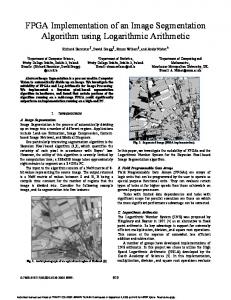
Figure 18: Asynchronous FPGA die photography.
needs one more PLB to implement its communication protocol. Up to now, these first results indicate that even if an absolute security could not be reached, a high security level is still possible for secured applications implemented on a dedicated asynchronous FPGA. Such an FPGA is a promising approach to counteract SCAs attacks (such as SPA, DPA, and timing attacks) while being flexible enough for secured systems that need to be regularly updated. To the best of our knowledge, it is the first Asynchronous FPGA which is designed with embedded countermeasures against sidechannel attacks. The prototype has been fabricated in CMOS 65 nm from STMicroelectronics (see Figure 18) and will be tested in a future work.
Acknowledgments The authors would like to thank Jean-Luc Danger, Sylvain Guilley, and Sumanta Chaudhuri, from Institut T´el´ecom ParisTech for the fruitful discussions and the shared design of the FPGA.
References [1] S. Wong, S. Vassiliadis, and S. Cotofana, “Futur directions of (Programmable and Reconfigurable) embedded processors,” in Proceedings of the Workshop on Systems, Architectures, Modeling and Simulation, Embedded Processor Design Challenges (SAMOS ’02), 2002. [2] P. Kocher, J. Jaffe, and B. Jun, “Timing attacks on implementations of Diffie-Hellman, RSA, DSS, and other systems,” in Proceedings of the 16th Annual International Cryptology Conference on Advances in Cryptology (CRYPTO ’96), vol. 1109 of Lecture Notes in Computer Science, pp. 104–113, Springer, Santa Barbara, Calif, USA, 1996. ¨ [3] S. B. Ors, F. G¨urkaynak, E. Oswald, and B. Preneel, “Poweranalysis attack on an ASIC AES implementation,” in Proceedings of the International Conference on Information Technology: Coding Computing (ITCC ’04), pp. 546–552, Washington, DC, USA, April 2004.
11 [4] P. Kocher, J. Jaffe, and B. Jun, “Differential power analysis,” in Proceedings of the 19th Annual International Cryptology Conference on Advances in Cryptology (CRYPTO ’99), vol. 1666 of Lecture Notes in Computer Science, pp. 388–397, Springer, 1999. [5] C. Rechberger and E. Oswald, “Practical Template Attacks,” in Proceedings of the 5th International Workshop on Information Security Applications (WISA ’04), vol. 3325 of Lecture Notes in Computer Science, pp. 443–457, Springer, Jeju Island, Korea, August 2004. [6] D. Agrawal, B. Archambeault, J. R. Rao, and P. Rohatgi, “The EM side-channel(s),” in Proceedings of the 4th International Workshop on Cryptographic Hardware and Embedded Systems (CHES ’02), vol. 2523 of Lecture Notes in Computer Science, pp. 29–45, Springer, Redwood Shores, Calif, USA, 2002. [7] M. Ward, “EMV card payments—an update,” Information Security Technical Report, vol. 11, no. 2, pp. 89–92, 2006. [8] F. Bouesse, G. Sicard, and M. Renaudin, “Path swapping method to improve DPA resistance of QDI asynchronous circuits,” in Proceedings of the 8th International Workshop on Cryptographic Hardware and Embedded Systems (CHES ’06), vol. 4249 of LNCS, pp. 384–398, Springer, Yokohama, Japan, October 2006. [9] T. Wollinger and C. Paar, “How Secure are FPGAs in cryptographic applications?” in 13th International Conference on Field Programmable Logic and Applications (FPL ’03), vol. 2778 of Lecture Notes in Computer Science, pp. 91–100, Lisbon, Portugal, September 2003. [10] A. J. Martin, A. Lines, R. Manohar et al., “The design of an asynchronous MIPS R3000 microprocessor,” in Proceedings of the 17th Conference on Advanced Research in VLSI (ARVLSI ’97), pp. 164–181, Ann Arbor, Mich, USA, September 1997. [11] A. J. Martin, M. Nystrom, K. Papadantonakis et al., “The Lutonium: a sub-nanojoule asynchronous 8051 microcontroller,” in Proceedings of the 9th International Symposium on Asynchronous Circuits and Systems (ASYNC ’03), pp. 14–23, Vancouver, Canada, May 2003. [12] J. D. Garside, W. J. Bainbridge, A. Bardsley A et al., “AMULET3i—an asynchronous syste-on-chip,” in Proceedings of the 6th International Symposium on Advanced Research in Asynchronous Circuits and Systems (ASYNC ’00), pp. 162–175, Eilat, Israel, April 2000. [13] R. Konishi, H. Ito, H. Nakada et al., “PCA-1: a fully asynchronous, self-reconfigurable LSI,” in Proceedings of the 7th International Symposium on Asynchronous Circuits and Systems (ASYNC ’01), pp. 54–61, March 2010. [14] J. Teifel and R. Manohar, “An asynchronous dataflow FPGA architecture,” IEEE Transactions on Computers, vol. 53, no. 11, pp. 1376–1392, 2004. [15] K. Maheswaran and V. Akella, “PGA-STC: programmable gate array for implementing self-timed circuits,” International Journal of Electronics, vol. 84, no. 3, pp. 255–267, 1998. [16] J. Teifel and R. Manohar, “Highly pipelined asynchronous FPGAs,” in Proceedings of the 12th ACM International Symposium on Field-Programmable Gate Arrays (FPGA ’04), pp. 133– 142, Monterey, Calif, USA, February 2004. [17] S. Hauck, G. Boriello, and C. Ebeling, “Montage: an FPGA for synchronous and asynchronous circuits,” in Proceedings of the 2nd International Workshop on Field-Programmable Logic and Applications, Vienna, Ausrtia, August 1992. [18] B. Gao, A globally asynchronous locally synchronous configurable array architecture for algorithlm embeddings [Ph.D. thesis], University of Edinburgh, 1996.
12 [19] R. Payne, Self timed field programmable gate array architectures [Ph.D. thesis], University of Edinburgh, 1997. [20] http://www.achronix.com/. [21] T. Beyrouthy, A. Razafindraibe, L. Fesquet et al., “A novel asynchronous e-FPGA architecture for security applications,” in Proceedings of the International Conference on Field Programmable Technology (ICFPT ’07), pp. 369–372, Kokurakita, Japan, December 2007. [22] S. Chaudhuri, S. Guilley, P. Hoogovost et al., “Physical Design of FPGA Interconnect to prevent Information Leakage,” in Proceedings of the 4th International Workshop on Reconfigurable Computing: Architectures, Tools and Applications (ARC ’08), Lecture Notes in Computer Science, pp. 87–98, 2008. [23] P. C. Kocher, J. Jaffe, and B. Jun, “Diferential power analysis,” in Proceedings of the 19th Annual International Cryptology Conference on Advances in Cryptology (CRYPTO ’99), M. Wiener, Ed., vol. 1666 of Lecture Notes in Computer Science, pp. 388–397, Springer, Santa Barbara, Calif, USA, 1999. [24] J. Quisquater and D. Samyde, “ElectroMagnetic Analysis (EMA): measures and counter-measures for smard cards,” in Proceedings of the International Conference on Research in Smart Cards (E-smart’01), vol. 2140 of Lecture Notes in Computer Science, pp. 200–210, 2001. [25] R. J. Anderson and M. G. Kuhn:, “Low cost attacks on tamper resistant devices,” in Proceedings of the 5th International Workshop on Security Protocols, B. Christianson, B. Crispo, M. Lomas, and M. Roe, Eds., vol. 1361 of Lecture Notes in Computer Science, pp. 125–136, Springer, Paris, France, April 1997. [26] S. Moore, R. Anderson, P. Cunningham, R. Mullins, and G. Taylor, “Improving smart card security using self-timed circuits,” in Proceedings of the 8th IEEE International Symposium on Asynchronous Circuits and Systems (ASYNC ’02), pp. 211–218, IEEE, 2002. [27] Y. Monnet, M. Renaudin, and R. Leveugle, “Designing resistant circuits against malicious faults injection using asynchronous logic,” IEEE Transactions on Computers, vol. 55, no. 9, pp. 1104– 1115, 2006. [28] L. Fesquet and M. Renaudin, “A programmable logic architecture for prototyping clockless circuits,” in Proceedings of the International Conference on Field Programmable Logic and Applications (FPL ’05), pp. 293–298, Tampere, Finland, August 2005. [29] N. Huot, H. Dubreuil, L. Fesquet, and M. Renaudin, “FPGA architecture for multi-style asynchronous logic,” in Proceedings of the Design, Automation and Test in Europe (DATE ’05), pp. 32–35, Munich, Germany, March 2005. [30] L. Fesquet, B. Folco, M. Steiner, and M. Renaudin:, “Stateholding in look-up tables: aopplication to asynchronous logic,” in Proceedings of the IFIP International Conference on Very Large Scale Integration (VLSI-SoC ’06), pp. 12–17, Nice, France, November 2006. [31] D. Solokov, J. Murphy, A. Bystrov, and A. Yakovlev, “Improving the Security of dual rail circuits,” in Proceedings of the Workshop on Cryptographic Hardware and Embedded Systems, Cambridge, Mass, USA, August 2004. [32] FIPS 46-3, “Data Encryption Standard (DES),” Specifies the Use of Triple DES, October 1999. [33] C. Canovas and J. Cl´edi`ere, “What do S-boxes say in fifferential side channel attacks?” Tech. Rep. 311, CEA-LETI, 2005.
International Journal of Reconfigurable Computing
International Journal of
Rotating Machinery
Engineering Journal of
Hindawi Publishing Corporation http://www.hindawi.com
Volume 2014
The Scientific World Journal Hindawi Publishing Corporation http://www.hindawi.com
Volume 2014
International Journal of
Distributed Sensor Networks
Journal of
Sensors Hindawi Publishing Corporation http://www.hindawi.com
Volume 2014
Hindawi Publishing Corporation http://www.hindawi.com
Volume 2014
Hindawi Publishing Corporation http://www.hindawi.com
Volume 2014
Journal of
Control Science and Engineering
Advances in
Civil Engineering Hindawi Publishing Corporation http://www.hindawi.com
Hindawi Publishing Corporation http://www.hindawi.com
Volume 2014
Volume 2014
Submit your manuscripts at http://www.hindawi.com Journal of
Journal of
Electrical and Computer Engineering
Robotics Hindawi Publishing Corporation http://www.hindawi.com
Hindawi Publishing Corporation http://www.hindawi.com
Volume 2014
Volume 2014
VLSI Design Advances in OptoElectronics
International Journal of
Navigation and Observation Hindawi Publishing Corporation http://www.hindawi.com
Volume 2014
Hindawi Publishing Corporation http://www.hindawi.com
Hindawi Publishing Corporation http://www.hindawi.com
Chemical Engineering Hindawi Publishing Corporation http://www.hindawi.com
Volume 2014
Volume 2014
Active and Passive Electronic Components
Antennas and Propagation Hindawi Publishing Corporation http://www.hindawi.com
Aerospace Engineering
Hindawi Publishing Corporation http://www.hindawi.com
Volume 2014
Hindawi Publishing Corporation http://www.hindawi.com
Volume 2014
Volume 2014
International Journal of
International Journal of
International Journal of
Modelling & Simulation in Engineering
Volume 2014
Hindawi Publishing Corporation http://www.hindawi.com
Volume 2014
Shock and Vibration Hindawi Publishing Corporation http://www.hindawi.com
Volume 2014
Advances in
Acoustics and Vibration Hindawi Publishing Corporation http://www.hindawi.com
Volume 2014