replaced by a single PC with software running under a real- time variant of the Linux ... tion) of objects moving in the robot workspace. .... servos of the C3G are used to move the robot. .... send drive on/off commands, to select the type of motion.
WC2-01
Proceedings of the 2005 IEEE/ASME International Conference on Advanced Intelligent Mechatronics Monterey, California, USA, 24-28 July, 2005
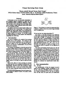
An Experimental Setup for Visual Servoing Applications on an Industrial Robotic Cell Vincenzo Lippiello, Bruno Siciliano, Luigi Villani Abstract— An experimental setup for visual servoing applications on an industrial robotic cell is presented in this paper. The setup is composed of two industrial robot manipulators equipped with pneumatic grippers, a vision system and a belt conveyor. The original industrial robot controllers have been replaced by a single PC with software running under a realtime variant of the Linux operative system. A vision-oriented software environment named VESPRO has been developed on a PC running under Windows NT operating system, which allows programming image processing and visual tracking tasks, using one or more cameras. Advanced user interfaces permit fast, safe and reliable prototyping of control schemes based on visual measurements both for the single robots and for the dual-arm robotic cell.
I. I NTRODUCTION
Fig. 1.
The development of advanced sensor-based control algorithms for industrial robots requires open control architectures where software modules can be modified and exteroceptive sensors like force/torque sensors and vision systems can be easily integrated. Various open control architectures for industrial robots have already been developed by robot and control manufacturers as well as in research labs (see, e.g., [1], [2]). Most of them are based on a standard PC hardware and a standard operating system. In fact, a PC-based controller can more easily integrate many commercially available add-on peripherals and allows standard software development tools (e.g., Visual C++, Visual Basic, Delphi, etc.) to be used. An important issue of control software architectures deals with real-time operating systems. In recent years the hard real-time variants of the Linux operating system (RTLinux [3] and RTAI-Linux [4]) are becoming widely adopted, especially in research labs [5], [6]. A common problem encountered in control architectures embedding visual measurements is that the time constraints of motion controllers are hardly met by the vision systems. This is especially true for position-based visual servoing [7], more than for image-based visual servoing [8]. In fact, the first approach requires computationally expensive operations to achieve the estimation of the pose (position and orientation) of objects moving in the robot workspace. This problem is usually solved by adopting a so-called “indirect” visual servoing scheme [9], based on an inner/outer feedback loop where the inner position feedback loop runs at a frequency higher than the outer visual feedback loop, to guarantee The authors di Informatica Napoli Federico
are with PRISMA Lab, Dipartimento e Sistemistica Universit`a degli Studi di II Via Claudio 21, 80125 Napoli, Italy
{lippiell,siciliano,lvillani}@unina.it
0-7803-9046-6/05/$20.00 ©2005 IEEE.
The dual-arm industrial robotic cell at PRISMA Lab
stability and disturbance rejection. This allows the time constraint of the visual feedback loop to be partially relaxed, so that non-hard real-time operating system can be adopted for the vision software. In this paper, an environment for visual servoing applications on the industrial cell of PRISMA Lab, based on two robots Comau SMART-3 S, is presented. The control architecture is an open version of the industrial Comau C3G 9000, developed at the PRISMA Lab, which allows controlling both the robots using a standard PC working with RTAI-Linux operating system. The open controller, named RePLiCS [10], allows advanced control schemes to be designed and tested, including dual-arm cooperation, force control, as well as visual servoing. The visual system runs on a separate PC working with Windows NT operating system. A vision-oriented software environment named VESPRO has been developed to manage a multi-camera system and to perform visual pose estimation of objects moving in the cell. As an example of application, a position-based visual servoing task, involving both robots of the cell, is described. II. T HE EXPERIMENTAL SETUP The setup in the PRISMA Lab consists of two industrial robots Comau SMART-3 S (see Fig. 1). Each robot manipulator has a six-revolute-joint anthropomorphic geometry with nonnull shoulder and elbow offsets and non-spherical wrist. One manipulator is mounted on a sliding track which provides an additional degree of mobility. The joints are actuated by brushless motors via gear trains; shaft absolute resolvers provide motor position measurements.
1431
PC
Force sensor readings
PC CPU
Parallel interface
Visual system readings
Serial interface
Pose Control (RePLiCS)
Gripper and belt conveyor communications
Desired Task
Smartlab interface
Dynamic Trajectory Planner
Motion Control
Robot
Joint feedback (500Hz)
ISA BUS
BIT 3 Adapter
C3G 9000
Visual feedback (26Hz)
Pose Estimation (VESPRO)
BIT 3 Adapter
Fig. 3.
VME BUS
Position-based visual servoing scheme
Motor currents
Robot CPU
Fig. 2.
Servo CPU
Joint readings
Schematic of the C3G open control architecture for one robot
Each robot is controlled by the C3G 9000 control unit which has a VME-based architecture with two processing boards (Servo CPU and Robot CPU) both based on a Motorola 68020/68882. The Robot CPU includes a shared memory area accessible by the other boards connected to the VME bus. Two BIT3 bus adapter boards allows the connection of the VME bus of the C3G 9000 unit to the ISA bus of a standard PC with RTAI-Linux operating system, so that the PC and C3G communicate via the shared memory of the Robot CPU. In this way the PC can be used to implement control algorithms, and time synchronization is achieved by means of a flag set by the C3G and read by the PC. A schematic of the open control architecture for one robot is sketched in Fig. 2. Seven different operating modes are available in the C3G, allowing the PC to interact with the original controller both at trajectory generation level and at joint control level. The most useful operating modes are number 4 and number 6. In operating mode number 4, the joint position servos managed by the C3G are opened and the PC is in charge of acquiring data from the resolvers, computing the control algorithm and passing the references to the current servos at 1 ms sampling time. Hence, the C3G is only used as an interface between the PC and the resolvers and the brushless motors of the robot. In operating mode number 6, the PC computes the joint position references for the microinterpolator of the Servo CPU of the C3G at 2 ms sampling time. Therefore, the PC is in charge of trajectory planning and kinematic inversion, while the native joint position servos of the C3G are used to move the robot. Each robot can be also equipped with a pneumatic gripper with two parallel jaws. The completion of the open and close operations are detected using Hall-effect sensors. The grippers can be directly commanded by the C3G industrial controller, or by the PC through a SMARTLAB ISA interface board. Through this board it is also possible to operate a belt conveyor.
A force/torque sensor ATI FT30-100 can be mounted at either arm’s wrist. The sensor is connected to the PC by a parallel interface board which provides readings of six components of force/torque at 1 ms. A vision system composed of a standard PC with Windows NT operating system, equipped with two MATROX Genesis boards and two SONY 8500CE B/W cameras is available. The MATROX boards are used as frame grabbers as well as for image processing (e.g., windows extraction from the image), while the PC host is in charge of executing visionbased algorithms and guarantees communication with the PC performing robot control via a serial and/or parallel connection. III. V ISUAL SERVOING The experimental setup may be used to perform both position-based and image-based visual servoing. For brevity, only position based visual servoing is considered here. This approach requires the estimation of the pose of a target object with respect to a reference frame by using the vision system; the estimated pose is then fed back to a pose controller. Hence, the two main operations to be performed are pose control and pose estimation (see Fig. 3). Notice that pose estimation is a computationally demanding task, because it requires processing of the measurements of some geometric features extracted from the images of one or more cameras. Hence, the sampling time of the pose estimation algorithm is usually higher than the sampling time of the pose control loop. In the best case, the pose estimation can be performed at camera frame rate (between 25 Hz and 60 Hz). Pose control is performed through an inner-outer control loop. The inner loop, running at 2 ms sampling time (i.e., 500 Hz frequency), implements motion control (independent joint control or any kind of joint space or task space control). In the outer loop, the block named dynamic trajectory planner computes the trajectory for the end-effector on the basis of the current object pose and on the desired task. The input of this block is updated at 26 Hz frequency, corresponding to the frame rate of the employed cameras, the output is available at 500 Hz frequency, thanks to a second order interpolating filter. The control software implementing pose control is RePLiCS.
1432
The pose estimation algorithm provides the measurements of the target object pose at 26 Hz frequency and is implemented by the software platform VESPRO. The vision system can be based on eye-in-hand cameras, i.e., one or two cameras mounted on the robot end-effector, or on eye-to-hand cameras, i.e., fixed cameras. Hybrid configurations, including both eye-in-hand and eye-to-hand cameras are possible as well. The use of a multi-camera system requires the adoption of intelligent and computationally efficient strategies for the management of highly redundant information (a large number of object image features from multiple points of view). This task has to be realized with real-time constraints and thus the extraction and interpretation of all the available visual information is not possible. To solve this problem, an efficient technique has been developed which is able to improve the accuracy and robustness of the visual system by exploiting a minimal set of significant data suitably selected from the initial redundant set. This technique, implemented in VESPRO, is described in [11], [12]; here only the main features are outlined. The pose estimation algorithm can be decomposed in three main parts: geometric modelling, redundancy management, motion estimation. The geometrical modelling part allows building computationally efficient geometrical representations of 3D polyedral objects using Binary Space Partitioning (BSP) tree structures [11] starting from simple CAD models. These are hierarchical data structures that provide an ordered representation of a 3D space containing one or more objects. Computationally efficient visit algorithms are available to evaluate the position of all the visible features of the objects (corners, holes, contours, etc.) in the image planes of the cameras, if an estimate of the object poses is available. The redundancy management part is in charge of dynamically selecting an optimal set of visible image features of the object, provided by the BSP tree visit algorithm. This is obtained by minimizing an optimal cost function based on a combination of suitable quality indexes ensuring an optimal spatial distribution of the projections of the feature points on the image plane of the camera. Moreover, in a multi-camera system, it is important to achieve an optimal distribution of the features among the different cameras, considering their different resolutions and focuses [12]. The motion estimation part is based on the Extended Kalman Filter, which provides an estimate of the pose and velocity of an object starting from a dynamic set of measurements of image features. The Kalman filter provides good robustness to noise and disturbances affecting visual measurements. Moreover, it allows exploiting redundancy of the information because the measurement set can be changed during the operation. This latter feature is implemented in VESPRO by generating on-line the equations of the filter output model on the basis of the features selected by the redundancy management algorithm. An adaptive formulation of the Extended Kalman Filter is also available to cope with the uncertainties of the statistics of the measurement noise
and of the object motion. IV. R E PL I CS The control software of the robotic cell, named RePLiCS (REal-time PrismaLab LInux Control System), can be structured into a real-time module, which is a driver for the kernel of RTAI-Linux, and a set of non real-time applications that provide a user interface for the real-time module. This is periodically activated by an external interrupt signal generated by the C3G controller. The real-time module of RePLiCS implements all the realtime functions required for the control of the robotic cell. All those functions are collected in an API (Application Programming Interface) software library written in the C language. These functions can be grouped in: • communication with the C3G controllers • synchronization for cooperative control • robot kinematics • robot control • trajectory planning • serial and parallel communication • force sensors reading • safety checks • data storage • I/O functions (file or console). The functions for the communication with the C3G controllers implement the drive on/off commands and have access to the shared memory area of the Robot CPUs to read the joint positions and write the current or the position set-points, depending on the selected operating mode. To implement cooperative control of the two robots, the PC should write the positions or the current set-points for both robots at the same time, on the basis of the motor angular positions read at the same time. This ideal behavior, however, is difficult to achieve because the two C3G controllers have two separate clocks. A synchronization module of RePLiCS has been developed to overcome this problem; details can be found in [10]. The functions used for robot kinematics allow the computation of the direct and inverse kinematics of the robots and their Jacobian matrices. Several utility functions are available, e.g., for unit conversion of the joint variables (degrees, radians, Bit resolvers), for coordinate conversion between different frames, for representation of the orientation (Euler angles, angle/axis, quaternion). The robot control functions implement decentralized joint control as well as centralized control, e.g., inverse dynamics or resolved acceleration in the task space. New control schemes can be easily programmed by modifying the control module of a template program file (written using the standard C language), which includes the API library. As for trajectory planning, a set of functions are available for the point-to-point motion, both in the joint and in the task space (along straight lines for the position) which use time laws with trapezoidal velocity profile. A function which allows generating a path (in the joint space or in the task
1433
RePLiCS MATROX Genesis Board
MATROX Genesis Board
Hardware Interface Feature Extraction
Motion Estimation
Feature Selection
Visual Task Module
Communication Object Recognition
Modelling
FS
Data
Driver Manager VESPRO Driver
Fig. 4.
VESPRO GUI
A screen-shot of all the RePLiCS GUI windows Fig. 5.
space) through assigned via points is also implemented. Special functions have been realized to achieve synchronization of the two robots at trajectory planning level, and generate smooth trajectories when the target is not known in advance (e.g., in visual servoing applications). The serial and parallel communications allow the controller to communicate with an external device (e.g., the PC used for the vision system) using the standard serial and parallel port. A set of functions have also been developed to command the two grippers and the belt conveyor through the SMARTLAB interface board. Details on the other functions available in the API library can be found in [10]. The applications in the user space are aimed at helping the human user to communicate with the robotic cell through a Graphical User Interface (GUI). In Fig. 4 all the GUI windows are collected in the same graphical page. The window on the top-left of Fig. 4 is the GUI of the main user application, which allows performing the most important operations on the system. In particular, by using the menu bar or the toolbar, it is possible: to select one of both the robots, to select the operating mode (4 or 6), to send drive on/off commands, to select the type of motion (joint space or task space) and to select the real or the virtual mode of operation. This latter feature is of the utmost importance, because it allows testing all the functionalities of the controller in a simulation environment which respects the real-time constraint and includes the C3G controllers, the robot dynamics and the interaction with a virtual environment. Hence, the whole control prototyping process can be developed off-line in a very fast, safe and reliable way; moreover, the same code developed in the virtual mode can be executed in the real mode without any modification, also using the real measurements of the exteroceptive sensors, if connected. A detailed description of the functionalities of all the GUI windows of RePLiCS can be found in [10]. From the main window it is also possible to compile and to
Schematic of the VESPRO software architecture
execute the control modules (linked to the real-time kernel) written by the user. For the execution of visual servoing tasks, a suitable visual task module is available as a user control module, which realizes the high level communication with VESPRO using the serial or parallel communication functions of RePLiCS. This module collects a number of functions that can be used for programming and executing visual servoing tasks, e.g., acquisition of object pose estimation, dynamic trajectory planning, check of workspace limits, check of consistency of the visual measurements, supervisory control. V. VESPRO VESPRO (Visually Enhanced System for PrismaLab Robot Operation) is a software environment able to manage a multi-camera visual system and to perform visual pose estimation of moving objects. It can be used both with eyein-hand and eye-to-hand cameras. It is structured into a low level driver (entirely written in C and in C++ languages) and a GUI for Windows NT operating system. The software architecture of VESPRO is represented in Fig. 5. It can be recognized that the driver is composed by a collection of software modules that can be activated and configured by a Driver Manager which translates the high level commands form the GUI. The Hardware Interface allows interfacing with the two MATROX Genesis boards, used as frame grabbers and image pre-processing. In particular, the low level functions of the boards are organized in high level functions that allows, e.g., image acquisition, image windows extraction, image preprocessing as binarization, convolution, etc. This is the sole VESPRO module to be hardware dependent (i.e., depending on the boards used as frame grabbers). It includes also a software library for the characterization of the cameras and the compensation of the main geometrical distortion phenomena.
1434
The Modelling module is in charge of managing a library of CAD model of objects and building BSP-tree geometric representations. The input of this module is an ASCII file containing a simplified description of the objects geometry based on a representation of increasing complexity. First of all, the coordinates of the feature points of each object are given, then these points are composed to define the object surfaces, and finally the surfaces are composed to achieve the object representation. The library allows building the representation of a single object and of a set of objects (that may also form a kinematic chain as a robotic arm) in a form suitable to derive a BSP-tree representation. Two functions are available to build a BSP-tree: one that use a dynamic memory allocation, and one that use a static memory allocation, which is faster but memory expensive. The Feature Selection module performs the dynamic choice of features that, at a given sampling time, have to be found and extracted from the image plane. This module includes occlusion prediction algorithms to locate the image feature that will be visible at the next sampling time, based on the BSP-tree representation of the cell built by the Modelling module. From the set of visible features, a subset of optimal features is selected, on the basis of some optimal criteria. For each optimal feature, an algorithm computes the optimal size of the window of the image plane to be used for feature extraction. The Feature Extraction module includes primitive functions for high level image processing, as edge detection (Sobel, Prewitt, Canny, Rothwell), corner detection (intersection of lines extracted using one of the previous methods, Susan, Sojka), holes and lines detection (under development). These functions depend on parameters that can be set form the GUI of VESPRO. An Object Recognition module is under development, that allows recognizing all the objects of the library of the Modelling module that are present in the cell. This module also allows the estimation of the pose of the recognized object. Graphical primitives are available for the manual selection and positioning of the graphical objects on the real objects in the scene. The Motion Estimation module is devoted to the realtime pose estimation based on the Extended Kalman Filter. This module includes also two independent adaptation mechanisms for updating the statistical parameters of the covariance matrices of the modelling and measurement errors. The equations of the output model of the Kalman filter are dynamically generated on the basis of the measurements currently available, independently from which camera provides the measurements. The Communication module allows interfacing VESPRO with the Visual Task module of RePLiCS. Finally, the Data module is in charge of recording the measurements and the main parameters and variables. The GUI of VESPRO allows the configurations of all the above modules using graphical objects. For example, it is possible setting the parameters of the Kalman filter and of the adaptation algorithm, the calibration parameters of
Robot 2
Robot 1
Target object
Camera 1
Fig. 6.
Camera 2
Sketch of the visual tracking experiment.
the cameras and those of the feature extraction algorithms. Moreover, it is possible to select the target objects from those available in the library and choosing the type of robot tool. One section of the GUI permits sending commands to the Visual Task module of RePLiCS (e.g., the execution of a grasping task, the synchronization of the robot motion with respect to the object motion). VI. E XPERIMENT An example of visual servoing task for the robotic cell is described below. The two robots (see Fig. 6) execute independent tasks. Robot 1 performs a grasping task of a moving object localized using the visual system. For this experiment, an eye-to-hand configuration with two cameras is adopted. Robot 2 performs a different task and during motion it may occlude the object with respect to the cameras. The task assigned to Robot 1 includes the following phases: 1) Approaching – When the target object is localized, starting from the HOME pose, approach the grasp pose in two steps: first go over the target object (at 5 cm height), and then descend on it. 2) Grasping – Grasp the object and check the state of the gripper; 3) Manipulating – Return to the HOME pose carrying the object. 4) Releasing – Go to the FINAL pose and release the object. The trajectory of the robot gripper and the estimated object position (the orientation is omitted for brevity) are shown in Fig. 7. The Approaching phase begins after about 4 sec and ends in about 11 sec. During this phase the robot recognizes the target object and moves over it, initially keeping a distance of about 5 cm along the vertical direction (z component); then the robot begins the descent to the grasping pose. Notice that the object is moving during this phase while the gripper motion in the horizontal plane (x and y components) matches the object motion. When the grasping pose has been reached, the Grasping phase begins and ends after about 2.5 sec. During this time interval the pneumatic gripper is closed and a check of the state of the gripper is performed using the magnetic sensors. At about 17.5 sec the Manipulating phase begins and the robot return to the HOME pose carrying the object. At about 40 sec the
1435
Manipulating
Grasping
Approaching
Releasing
z
B y
A
x
Fig. 7. Gripper (solid) and estimated object (dashed) trajectories during the first experiment.
B robot reaches the FINAL pose and releases the object; then, it returns to HOME (Releasing phase). In Fig. 8 the state of the visible and selected object feature points during the experiment are represented; the total number of image features (object corners) is 16. For each point, the bottom line indicates when it is visible, the top line indicates when it is selected for feature extraction. The maximum number of visible image features, for both cameras, is 32, but the selection algorithm, at each sampling time, chooses a subset of 11 optimal features to be extracted. The A-area corresponds to the occlusion caused by the gripper during the grasping, while the B-area corresponds to the occlusion caused by Robot 1. Notice that the motion of Robot 1 generates a partial occlusion (only on point remains visible) on the Camera 2 between the Approach and the Grasping phase. This event does not affect the accuracy of pose estimation and allows the successful execution of the Grasping phase. Moreover, during the Manipulating phase, Robot 1 occludes completely the object with respect to Camera 1. Again, the visual tracking algorithm maintains high accuracy, even though the estimated pose is not used after grasping (only the joint resolver measurements are used in the Manipulating and Releasing phases). VII. C ONCLUSION In this work an experimental setup for visual servoing applications on an industrial robotic cell has been presented. The software architecture includes an open controller for the two robots of the cell, based on RTAI-Linux, and a vision system based of multiple cameras in eye-in-hand, eye-tohand or hybrid configurations. The setup allows testing both image-based and position-based visual servoing algorithms. In this work a position-based scheme is illustrated where the visual system is in charge of estimating the pose of one or more target objects. A visual tracking technique has been implemented, which guarantees accurate estimation at camera frame rate, also in the presence of occlusions. An experimental test where a robot grasps an object partially occluded by the other robot has been illustrated.
A
Fig. 8. Visible and selected object feature points for Camera 1 (top) and Camera 2 (bottom).
ACKNOWLEDGMENTS The authors wish to thank Nello Grimaldi for the significant support to the development of RePLiCS. R EFERENCES [1] [2] [3] [4] [5] [6]
http://www.mitsubishielectric.com http://www.robot.lth.se http://www.rtlinux.org http://www.rtai.org http://www.gnu.org A. Macchelli, C. Melchiorri, “Real time control system for industrial robots and control applications based on real time Linux,” Proc. 15th IFAC World Congress, Barcelona, Spain, pp. 21–26, 2002. [7] W.J. Wilson, C.W. Hulls, and G. Bell, “Relative end-effector control using cartesian position based visual servoing,” IEEE Trans. on Robotics and Automation, vol. 12, pp. 684–696, 1996. [8] B. Espiau, F. Chaumette, and P. Rives, “A new approach to visual servoing in robotics,” IEEE Trans. on Robotics and Automation, vol. 8, pp. 313–326, 1992. [9] S. Hutchinson, G.D. Hager, and P.I. Corke, “A tutorial on visual servo control,” IEEE Trans. on Robotics and Automation, vol. 12, pp. 651–670, 1996. [10] F. Caccavale, V. Lippiello, B. Siciliano, L. Villani, “RePLiCS: An environment for open real-time control of a dual-arm industrial robotic cell based on RTAI-Linux, ”submitted to 2005 IEEE/RSJ Int. Conf. on Intelligent Robots and Systems, Edmonton, Canada, August 2005. [11] V. Lippiello, B. Siciliano, L. Villani, ”3-D objects motion estimation based on Kalman filter and BSP tree models for robot stereo vision”, Archives of Control Science, vol. 12, pp. 71–78, 2002. [12] V. Lippiello and L. Villani, “Managing redundant visual measurements for accurate pose tracking,” Robotica, vol. 21, pp. 511-519, 2003.
1436