Ergun, and B.T. Khuri-Yakub. Edward L. Cinzton Laboratory, Stanford University, Stanford, CA 94305-4088. Tel: 1-650-725-2990, Fax: 1-650-725-7509.
AN IMPLEMENTATION OF A MICROFLUIDIC MIXER AND SWITCH USING MICROMACHINED ACOUSTIC TRANSDUCERS H. Jagannathan, G.G. Yaralioglu, AS. Ergun, and B.T. Khuri-Yakub Edward L. Cinzton Laboratory, Stanford University, Stanford, CA 94305-4088 Tel: 1-650-725-2990, Fax: 1-650-725-7509
ABSTRACT
It should also he noted that the transducer can be located both inside and outside the channel giving an additional degree of flexibility in its fabrication.
This paper presents the results of fluidic switching and mixing, performed in microfluidic channels, integrated with micromachined acoustic transducers. The transducers operate at 400 MHz while the microfluidic channels are made by casting polydimethylsiloxane (PDMS) on silicon moulds. Rapid switching is incorporated by applying pressure waves in one of the two outlet channels to get preferential flow. Radiation pressure is also utilized to obtain active mixing of fluids within the channel. This method of switching and mixing has the advantages of simple design and ease of integration into larger systems.
FABRICATION OF CHANNELS AND TRANSDUCER The micro channels used in our experiments for switching and mixing are made from PDMS by casting silicone rubber on wafers containing patterned and etched channels. Figure 1 shows the steps of fabrication of this master wafer. A dry Silicon etch with a high aspect ratio is used to obtain vertical walls. Channels with a height of IOOKm, 200pm, 300pm and 500pm were fabricated.
INTRODUCTION The field of microfluidics has given rise to many exciting possibilities that range from Micro-Total Analysis systems to portable bio-chemical devices [I]. Such systems are often very small and require minute quantities of reagents and fluid:j for their operation. This makes microfluidic systems an exciting and lucrative substitute for many processes used today. Nevertheless, the implementation of a microfluidic system has its share of difficulties. The characteristic laminar flow that occurs in micronscale channels makes mixing of two fluids a very challenging operation. This can be a serious problem in systems that require the interaction between hvo or more fluids. Many mixers, both active and passive, have been demonstrated utilizing different methods [2,3]. Moving small inert beads inside the fluid and applying alternating electric fields (electrokinetic mixing) are two such methods. An alternative method of mixing using acoustics is discussed in this paper [4]. Furthermore, the routing of fluids is even inore challenging due to the small scales involved. MEMS switches [5,6] with moving components show a high failure rate and deteriorate in performance with rime. The acoustic implementation of a microfluidic switch gives reliable and stable-switching as it does not have moving components. The acoustic implementation of both micro-mixers and micro-switches share many benefits such as ease of design and fabrication, having no moving components, being non-invasive and being easy to integrate in many existing systems.
0-7803-7744-3/03/$17.00 02003 IEEE.
$7775 Sillcan SublVate
Pholorer,rt PMS
Figure I . Steps in fabrication of Silicon Master The ultrasonic transducers used in the experiments are made by sandwiching thin films of Zinc Oxide in between gold layers. The piezoelectric property of Zinc Oxide is used to convert the applied electrical energy into acoustic energy. Figure 2 describes the steps involved in the fabrication of the transducer. First, a thin film of gold is sputtered and patterned over a quartz substrate to function as one of the electrodes of the transducer. This is followed by a deposition of Zinc Oxide by means of Magnetron Sputtering using a shadow mask. Finally, another layer of gold is deposited and patterned using lift-off to function as the top electrode of the transducer.
104
-
r:. >. m.
.. ... ..... . -
..:.
4
, PDMS
5
2
outpu
3
6
.
Mm"g
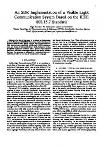
Figure 4. Schematic drawing of an Acoustic Mixer
0 oum S"i**~tc Gall P"Q"9,ll
I,"tO.,de
Figure 2. Steps in fabrication of Ultrasonic Transducer The final microfluidic device that was used in our experiments is shown in Figure 3 by aligning the fabricated transducer and channel under a microscope. The fluidic chip is then placed on a custom made printed circuit hoard and wire bonded to the necessary electronics.
Two different fluids are pumped thorough the inlets and mixing is performed at the vicinity of the transducer. As shown in Figure 5 , the two fluids can he seen to flow side by side with no mixing in normal conditions. Figure 6 shows the mixing of two fluids when a continuous wave signal is applied to the transducer. A more thorough mixing can be achieved by using an array of such transducers.
Figure 5 . Laminar flow in Micro-channels
Figure 3 . Photograph of a fabricated ultrasonic microfluidic device ULTRASONIC MIXING The mixing of fluids in micro-channels is a challenging task due to the low Reynolds numbers involved. In such channels, the flow of the fluid is laminar as shown in Figure 5 , and the mixing between the interfaces is dominated by diffusion, which can be a very slow process. An ultrasonic transducer is intemated within the channel to radiate acoustic waves into channel. The RF radiation field creates a DC pressure in the field view of the transducer disrupting the interface between the fluids and rapidly increasing the rate of mixing. This DC pressure field associated with the high frequency acoustic wave propagation is called radiation pressure [7]. ~~i~~ ~~~~
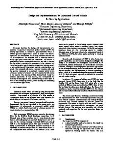
Figure 6. Mixing in Micro-channels The acoustic transducers were also integrated with larger channels obtained from Motorola. Figure 7 shows the acoustic stirring that was seen in the fluid. The vortices produced in the fluid by the acoustic transducer are made visible by introducing dyed heads to the fluid.
The schematic drawing of the acoustic mixer is shown in Figure 4.
105
Figure 1. Vortices produces from the Acoustic Transducer
ULTRASONIC SWITCHING The ability to switch fluids in micro-channels can he a very powerful method in reducing the total number of channels in a complicated system. The acoustic implementation of a microfluidic switch involves two transducers being placed at the inlet of the corresponding channels as shown in Figure 8. By applying a continuous wave signal to the transducer, a radiation pressure is created at that corresponding inlet causing preferential fluid flow into the other channel. It has been verified from the experiments that the change of flow from one channel to the other can be done quickly and can be implemented with relatively simple electronics.
-.-
Transduc
Figure 9. Switching using Acoustic Transducers As illustrated in figure 9, the beads are prevented to enter one channel and clutter at the inlet of the blocked channel. A small amount of leakage was observed making this method not suitable for completely blocking the flow in both the channels.
CONCLUSION We have demonstrated the ability to perform mixing
Figure S. Working ofan Acoustic Switch Figure 9 shows pictures of the fluids being switched from one channel to another. Colored heads are added to the fluid to make the switching visible. The figures show that on turning the corresponding transducer on, the beads flow into the other channel depicted with the arrows.
and switching of fluids in microfluidic channels using ultrasonic transducers. The mixing was observed to occur in the field view of the transducer. Fluidic switching by creating a preferential flow in a channel was also performed. Since this method involves thin film depositions on the channel, it provides an easy fit with many existing systems currently in use. Future work includes the use of Capacitive Micromachined Ultrasonic Transducers (CMUTs) instead of Zinc Oxide as the transducer.
ACKNOWLEDGEMENTS This work was made possible by support from the Defense Advanced Research Program Agency (DARPA) under the BIOFLIPS program. We would also like to thank Motorola for providing us with channels for testing our mixers.
REFERENCES 1. Chih-Ming Ho, “Fluidics The link between micro and nano sciences and technologies”, Proc. IEEE International conference on MEMS, (2001), 375-384. 2. M. H. Oddy, J. G. Santiago, and J. C. Mikkelsen, “Electrokinetic Instability Micromixing,“ Anal. Chem.2001, Vol. 73, No. 24, pp5822-5832 3. J. Evans, D. Liepmann, D. Pisano, “Planar Laminar Mixer”, MEMS97, pp 96-101. 4. H. Jagannathan, G. Yaralioglu, A. S. Ergun, F. L. Degertekin, and B. T. Khuri-Yakub, “Microfludic Channels with Integrated Ultrasonic Transducers,” in Proceedings of 2001 IEEE International Ultrasonics Symposium (October 7-10, 2001, Atlanta, Georgia), pp. 903-906
5. Smith, L. and B. Hok, “A Silicon Self-Aligned Non- Reverse Valve,” Transducers 91, pp 10491051. 6. J. Tiren, L. Tenerz, and B. Hok, “A batchfabricated non-reverse valve with cantilever beam manufactured by micromachining of silicon,” Sensors and Actuators, vol. IS, 1989, pp. 389-396. 7. B-T. Chu, and R.E. Apfel, “Acoustic radiation pressure produced by a beam of sound,” Journal of Acoustical Society of America, Vol. 72, 1673, 1982.
107