AbstractâA novel rank order statistic calculation algorithm for OS CFAR is presented. OS CFAR gives improved performance in a multitarget environment as ...
Design and Implementation of an OS-CFAR Processor Based on a New Rank Order Filtering Algorithm Zulfiqar Ali, Ali Arshad, Umair Razzaq, Sawaira Sana Irtiqa Technologies, Islamabad, Pakistan. {zulfiqar, ali, umair}@irtiqa.com
Abdul Haseeb Ahmed U Michigan Ann Arbor, Michigan, USA.
Abstract—A novel rank order statistic calculation algorithm for OS CFAR is presented. OS CFAR gives improved performance in a multitarget environment as compared to CA CFAR. However, the computational requirements of sorting data arrays complicate its implementation. We present an algorithm to overcome this challenge by employing a rank order statistic finding algorithm coupled with the exploitation of parallelism offered by FPGAs. In this technique previously computed results are used to successively divide the data array in order to find the new rank order value. The design is tested on MTI processed data from a TA-10K air traffic control radar and is part of a single chip FPGA based radar signal processor. It is implemented on a Virtex-4SX35 FPGA using the Xilinx XtremeDSP kit.
I.
INTRODUCTION
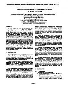
Fixed radar threshold detection assumes a constant interference and noise level to set a constant probability of false alarm. However, in practice, interference levels in radar signal are a function of time and environment. Constant False Alarm Rate (CFAR) detection incorporating an adaptive thresholding algorithm based on background estimation is used to ensure a predictable false alarm behavior [1]. Background interference level is estimated from the surrounding cells of the cell under test (CUT) using a variety of techniques. Cell Averaging CFAR (CA CFAR) uses the mean value of a specified number of surrounding cells to compute a threshold for a particular CUT. CA CFAR suffers performance degradation in presence of nonhomogenous interference [2]. There is also a chance of target masking if two or more targets are present in close vicinity. Rank based algorithms such as Order Statistic CFAR (OS CFAR) show an improved performance in multiple target environments inside the sliding window [3]. This fact is elaborated in Fig. 1, where one of the two close targets is masked in case of CA CFAR, whereas both are successfully qualified by OS CFAR. However there is a downside to this as OS CFAR involves sorting the cell array window to obtain a threshold for each CUT. This is a computation intensive operation compared to the mean finding required for CA CFAR. Various solutions have been proposed previously to overcome the computational requirements imposed by
c 978-1-4244-8278-8/10/$26.00 2010 IEEE
Abdullah M. Harris Aalto University of Technology Helsinki, Finland.
sorting the data array. One approach could be to use a fully parallel architecture to sort the complete data array based on sorting networks. However, a more efficient approach is to find the rank order sample without sorting the complete window. This finds applications not only in radar signal processing but also in median filtering used for removing impulse noise in images and is thus a popular research interest. Magaz and Bencheikh[4] have proposed an FPGA implementation scheme for OS CFAR that involves finding the Kth order element by iteratively finding the window maxima N-K+1 times where ‘N’ is the number of reference cells in the window and ‘K’ is the rank order. The worst case scenario would occur if median is to be found. The number of clock cycles required to find the rank order is fixed and does not take advantage of the result computed in the previous iteration. Moreover, the maxima finding tree structure grows as the window size grows and thus the required comparators increase in a non-linear manner. Two methods for rank order filtering are proposed in [5] and [6]. These are bit-serial algorithms that are based on data decomposition. The same bit of all elements in the window is compared for dividing the data into two groups in each iteration. Lee [7] has also proposed a similar bit-serial sorting algorithm for the special case of median finding. The performance of these algorithms is data independent and the same number of cycles is consumed for a given number of bits per element. In radar applications, an OS-CFAR processor would typically receive data from a Moving Target Indication block that serves to remove clutter from stationary objects. Higher order FIR or IIR filters may be required for MTI filtering and thus the resultant data may have a much higher number of bits compared to the number of bits of a typical A/D converter operating in the 2-20 MHz range [8]. A bit serial approach may not be suitable for such large bit numbers. In this paper, we propose a design for an FPGA based OS CFAR processor which is a part of a single chip radar signal processor also incorporating the preceding algorithms. The design includes a new rank order filtering technique that gives the required speed while keeping area consumed to a level whereby the other algorithms can be ported on the same device.
158
is a bit parallel one that uses the previously calculated rank order as a seed value for the next calculation. The window is divided and sub-divided into chunks through a series of comparisons until the algorithm converges to the rank order value. Multiple instances of the K-finding core are used to speed up the computation to the desired level. The Kth value is scaled and compared with CUT. Whenever a target declaration is made, a packet synthesizer writes the target information into a FIFO that is read by the host PC on an interrupt. III.
Figure 1 OS CFAR on baseband data The paper is organized as follows. In section 2, we give a brief description of the general OS CFAR algorithm along with the data flow of the proposed OS CFAR processor. In section 3, a new rank order calculation algorithm is presented. The implementation scheme for the complete OS CFAR processor is presented in Section 4. Section 5 discusses the results of implementation on a Virtex4SX35 device. The paper is concluded in section 6. II.
ALGORITHM AND DESIGN FLOW
OS CFAR rank orders the window data consisting of N samples to form a new sequence in ascending order. The samples {x1,x2,…,xN} are ordered as { x(1),x(2),…,x(N) } where the Kth element, known as the Kth order statistic, is scaled to compute the threshold for target qualification. Fig.2 shows a general OS CFAR process. The MTI processed data is fed to the OS CFAR processor via a buffer. This buffer is filled by a host computer while the processor is running in test mode. In running mode, this data is supplied by the previous processing block i.e. MTI processor. The data is read from this buffer into another buffer of size N+1 which includes N reference window cells and cell under test (CUT). The proposed K-finding engine computes the Kth order statistic from this window. The K-finding algorithm
Figure 2 General OS CFAR process
159
PROPOSED K-FINDER ALGORITHM
We now present a new algorithm for finding rank order statistic suitable for OS CFAR. The algorithm directly finds the rank order statistic eliminating the need to sort the complete data window. As opposed to the algorithms discussed earlier, this recursive method uses the previously computed results to calculate the new rank order value. This algorithm exploits the sliding window nature of the OS CFAR whereby only two samples change in the reference window for each calculation. Fig.3 gives the algorithm for finding the Kth value. Given a reference window with elements {x1,x2,…,xN},we have to find xK where K is the rank order. After each calculation two new elements enter the reference window i.e. the new sample value and the previous CUT value. At the start of a new calculation the new elements entering the reference window are compared with the previous Kth value, known as the pivot value. The comparison result for old elements is used as such. The reference data window is always divided into two sub-windows, the lower one holding elements smaller than or equal to the pivot value, while upper one having greater elements. The pivot value for the first iteration will be the previous Kth value. For the subsequent iterations, it will be the integer mean value of the selected sub-window. A variable Cu holds the current count of the elements greater than the pivot value in the current sub-window. Another variable Tu holds the total count of eliminated greater elements and is updated after each iteration. One of the sub-windows contains the required Kth value. This will be the upper sub-window if Tu is greater than N-K and the lower one otherwise. The greater values are eliminated if Tu is smaller than or equal in size to N-K, and the lower sub-window is selected for further processing. The selected sub-window is further divided on the basis of comparison with their average. The process is repeated until Cu is zero. At this time Tu is equal to N-K and the last value left is the Kth value. Tables 1 and 2 illustrate a worked example on arbitrary data with a window size N of 10 and K equal to 7. Table 1 shows input data with previous Kth order value (6 in this case) taken as pivot value. Table 2 illustrates the next run where two samples (5&28) have been replaced by two new ones (3&4). The same procedure is followed and the new Kth value is computed.
transposition as the number of elements are increased. Odd even transposition, if used in a time shared manner whereby the same set of N/2 comparators are fed the results from the previous iteration, would save hardware resources but decrease throughput drastically. IV.
Figure 3 K-Finder algorithm TABLE 1 Reference window
Pivot
Cu
5, ↑13, 2, ↑11, ↑19, ↑28, 6, 3, 1, ↑9
6
5
13, 11, 19, 28, 9 (upper) ↑13, 11, ↑19, ↑28, 9
Tu 5 0
12
3
3
10
1
4
11
11
0
3
Reference window
Pivot
Cu
Tu
↑13, 2, 11, ↑19, 3, 6, 3, 1, 9, 4
11
2
11, 9 (lower) ↑11, 9
3
11 (upper)
3
TABLE 2
2, 11, 3, 6, 3, 1, 9, 4 (lower) 2, ↑11, 3, ↑6, 3, 1, ↑9, 4
4
3
5
8
2
4
10
1
11, 6, 9 (upper) ↑11, 6, ↑9
2
11, 9 (upper) ↑11, 9
2
9 (lower) 9
2 2
3 3
9
0
IMPLEMENTATION
The intensive computational requirements imposed by the OS-CFAR algorithm makes it essential to exploit the inherent parallelism of the algorithm. This can be achieved by dividing the input data into n chunks. This logically partitioned shared memory space is accessed by n processing cores running in parallel to produce n threshold values at a time. The block diagram for complete OS-CFAR is shown in Fig.4. The processor can be divided into three sub units namely memory access, K-finder & thresholding and the packet synthesizer. Memory access unit controls the reading of input data to the parallel processing cores. The cores evaluate the Kth rank order each time a new data is read and compute the threshold value. Packet synthesizer creates and transfers a 32 bit target packet to the host machine once a target is declared. The detailed architecture of each is described below. A. Memory access unit Fig.5 shows the memory reading scheme. The shared memory space is built around a Virtex-4 block RAM (BRAM). It is a ping pong buffer that can hold two MTI processed returns at a time. The reading addresses from the n processing cores are multiplexed by the memory access unit. A read flag register controls the read address to the buffer. The memory access unit clears the read flag after a read request has been serviced, increments the reading address for that particular core and moves on to the next request from another core. Though the memory is divided into chunks with each chunk being accessed by its corresponding processing core, the memory space of two adjacent processing cores overlaps. This is due to the fact that OS CFAR requires neighboring cells to compute threshold value for each CUT. This overlap size is equal to the reference window size.
3
The proposed K-finder has advantages over [4] as the calculation time is independent of the rank order. There is no “worst case” scenario with respect to the rank order that has to be found. Any rank order may be calculated with equal efficiency. Also the calculation time does not increase as rapidly when the number of elements in the reference window is increased. The algorithm has advantages over bitserial architectures as bit sizes after higher order MTI processing may approach much greater values compared to normal A/D bit sizes. This may make the calculation time prohibitively long. The hardware growth of the algorithm is much lesser than that of sorting networks or odd-even
Figure 4 OS CFAR processor block diagram
160
INPUT STREAM
DATA SAMPLE1
AVG
PU1 AVG
DATA SAMPLE2
PU2 AVG AVERAGE
DATA SAMPLE3
PU3
AVG
DATA SAMPLEN-1
Figure 5 Memory access scheme
PUN‐1 AVG
B. K-finder and thresholding These units constitute the processing cores of the design. Fig.7 shows the K-finder implementation scheme. The Kfinder is built around a basic Processing Unit (PU) that contains the comparison and sub-window selection logic. Fig.6 shows the architectural detail for the basic PU. There are N flip flops labeled as U1 to UN that hold the comparison result for each element of the current window. Similarly, there is another set of N flip flops named E1 to EN that hold the elimination bit for each element in the reference window. A number that has its elimination bit set is permanently eliminated from the calculation. The corresponding flip flops from the E and U groups are fed to a particular PU for the selection decision of that element for new sub-window. The register Cu holds the count of 1s in the U flip flop group. The registers feeding the K-finder with a new data element after each calculation are initialized with a value of 1 when the FPGA is configured. This is the seed value for the first computation. The integer mean calculation of the current sub-window is controlled by the PU. The integer mean is calculated for a number of ‘p’ values such that 1≤p≤N. In order to achieve division by p, a look up table of N values holding all the possible reciprocal values of p is built using Virtex-4 distributed ROM. This value is multiplied with the sum of ‘p’ current window elements to get integer mean.
Figure 6 Processing Unit design
161
DATA SAMPLEN
PUN
Figure 7 K-Finder implementation C. Packet synthesizer The packet synthesizer is triggered once a target is declared as a result of thresholding. There is a single synthesizer unit that is used by all the cores running in parallel. There is an n-bit flag register to synchronize packet synthesizing requests from the different processing cores. The 32-bit packet contains all the required information about the target. Fig.8 shows the target packet format. This module contains separate range bin counters for each processing core.
Figure 8 Target Packet format V.
RESULTS
The OS CFAR processor incorporating the proposed Kfinder has been ported on a Virtex-4SX35 FPGA using the Xilinx XtremeDSP kit. The processor is tested by supplying MTI processed data from a functional TA-10K radar as input. There is a total of 1650 range bins per radar return array. Thus 1650 thresholds have to be calculated in a time interval of 1.4msec, which is the pulse repetition interval for TA-10K radar. The speed requirements in this case are met with two processing cores operating at 30MHz. The design is extendible to N processing cores. The complete OS CFAR processor utilizes 11% of the available slices for one processing core. Device utilization and estimated static power consumption as a function of N are presented in Table3.
TABLE 3
No. of cores ‘N’ 1 2 4 8
[2]
Device utilization (slices) 1755 (11%) 3465 (22%) 6826 (44%) 13957 (90%) VI.
Power consumption(W) 0.06779 0.11893 0.1663 0.23909
CONCLUSION
This paper presented design and implementation of an FPGA based OS CFAR processor. The highlight of the design is a novel rank order calculation algorithm that eliminated the need for sorting. The algorithm is equally efficient for any rank order value. An FPGA implementation of the OS CFAR processor has been presented. The design meets the speed requirements while keeping the device utilization inside the required limits. This ensures complete implementation of the radar signal processor on a single chip. REFERENCES [1]
[3]
[4]
[5]
[6]
[7]
[8]
Mark A. Richards “Fundamentals of radar signal processing”. pp 347-374. McGraw-Hill 2005.
162
Mohammad Ali Khaligi, Muhammad Hasan Bastani, “ Adaptive CFAR processor for Nonhomogeneous Environments”, IEEE Trans on AES, vol. 36(3), pp. 889-897, 2000. Rohling H, “Radar CFAR Thresholding in Clutter and Multiple Target Situation”, IEEE Transactions on AES, vol. 19(4), pp 608-621, 1983. B. Magaz, M.L Bencheikh, “An Efficient FPGA Implementation of the OS-CFAR Processor” International Radar Symposium 2008. Barun K. Kar, Dhiraj K. Pradhan, “A New Algorithm for Order Statistic and Sorting”, IEEE Trans on Signal Processing, vol 41(8), pp. 2688-2694, 1993. K. Benkrid, D. Crooks, A. Benkrid, “Design and implementation of a novel algorithm for general purpose median filtering on FPGAs”, IEEE International Symposium on Circuits and Systems, pp. IV 425- IV 428, 2002. Tae-Wook Lee, Jong-Hwa Lee, Sang Bock Cho, “FPGA implementation of a 3x3 Window Median Filter Based on a New Efficient Bit-Serial Sorting Algorithm”, Proceedings of the 7th Korea-Russia International Symposium, KORUS 2003, pp. 237-242. Z. Ali, A. Arshad, U. Razzaq, “An FPGA based semi-parallel architecture for higher order Moving Target Indication (MTI) processing”, Unpublished.