AN IMPLEMENTATION OF THE FELDKAMP ALGORITHM FOR MEDICAL IMAGING ON CELL Masaharu Sakamoto IBM Japan 1623-14 Shimo-tsuruma Yamato-shi, Kanagawa-ken, Japan, 242-8502 +81-46-215-4599
[email protected]
Hiroki Nishiyama IBM Japan 800, Ichimiyake, Yasu-shi, Shiga-ken, Japan 520-2392 +81-77-587-7688
[email protected]
Hitoshi Satoh IBM Japan 1623-14 Shimo-tsuruma Yamato-shi, Kanagawa-ken, Japan, 242-8502 +81-46-215-5276
[email protected]
Shigenori Shimizu IBM Japan 1623-14 Shimo-tsuruma Yamato-shi, Kanagawa-ken, Japan, 242-8502 +81-46-215-4880
[email protected]
Toshiyuki Sanuki IBM Japan 19-21 Nihonbashi Hakozaki-cho, Chuoh-ku, Tokyo, Japan, 103-8510 +81-3-5644-9174
[email protected]
Kohich Kamijoh IBM-Japan 1623-14 Shimo-tsuruma Yamato-shi, Kanagawa-ken, Japan, 242-8502 +81-77-587-2238
[email protected]
Atsushi Watanabe IBM Japan 1623-14 Shimo-tsuruma Yamato-shi, Kanagawa-ken, Japan, 242-8502 +81-46-215-6834
[email protected]
Akihiro Asahara IBM Japan 800, Ichimiyake, Yasu-shi, Shiga-ken, Japan 520-2392 +81-77-587-7727
[email protected]
ABSTRACT The Cell Broadband Engine Architecture (CBEA) is a novel microprocessor architecture designed to provide power-efficient and cost-effective high-performance processing for some of the world’s most demanding applications, including next generation game consoles. Applications that show special promise of benefiting from CBEA are medical imaging, security and surveillance, digital media, entertainment, communications, and selected scientific workloads. A medical imaging application for 3D CT image reconstruction, which is one of our application studies for the new architecture, is a good example to demonstrate the unique capabilities of CBEA. However, the programming scheme of CBEA is different from a single-core architecture. In this paper, we describe the parallelization of the 3D image reconstruction algorithm on CBEA. The results show that CBEA is viable for 3D CT image reconstruction and results in run time savings. Keywords Computer Tomography (CT), Cone-beam, Feldkamp algorithm, Backprojection, Cell Broadband Engine (CBE), Power Processor Element (PPE), Synergistic Processor Element (SPE),
Single Instruction Multiple Data (SIMD), Direct Memory Access (DMA) 1. INTRODUCTION Cone beam X-ray computed tomography (CT) reconstructs a volume from cone-beam projections. The advantages of cone beam X-ray CT are that it can obtain the X-ray projection images required for reconstructing a volume in shorter time than the conventional technique, and that the volume image has isotropic voxels. Cone beam X-ray CT includes not only medical applications, but non-destructive inspection systems and explosive detection systems for airports. However, in most applications, the 3D image reconstruction is still a very demanding computational task. The reconstruction from projections is done using special algorithms with high operational complexity—O(N4) where N is the number of detector pixels in one detector row. In generally, the cone beam X-ray CT device needs special computational hardware for the 3D image reconstruction. According to [8], when using a detector with 1,0242 pixels, the projection data occupies approximately 1.6 GB and the reconstruction of the 1,0243-voxel volume takes 90 minutes on a single PC. The Cell Broadband Engine (CBE) consists of two different types of processor elements called PowerPC
Processor Element (PPE), and multiple Synergistic Processor Elements (SPEs) respectively [9]. The programming scheme of CBEA is different from a singlecore architecture. The programmer needs to take into account of appropriate design for application partitioning between PPE and SPEs. The synchronization among each processor element (PPE and its SPEs) is also an important factor. The optimization to fit the size of the Local Storage (LS) is also another factor. In this paper, we discuss how the 3D image reconstruction problem can be implemented on the CBEA. The organization of the paper is as follows. In Section 2, we describe the 3D-CT and the Feldkamp Algorithm for reconstructing the original volume from the projection images. In Section 3, we describe the implementation of the Feldkamp Algorithm on CBEA. In Section 4, we describe the experimental results of our implementation. In section 5, we discuss on the performance metrics. Finally, Section 6 concludes the paper and describes the future work.
The cone-beam CT can scan a wider area, in a shorter time, than the multi-slice CT. However, since current computer systems are slower than desired for practical uses, a dedicated computer system is used for cone beam reconstruction.
2. 3D CT AND THE FELDKAMP ALGORITHM 2.1. Cone beam CT X-ray CT makes a cross-sectional X-ray picture of a "slice" of the target. The machine rotates around the patient taking X-rays from different angles. The computer processes the projection images to reconstruct the original volume. The projections are transferred to a high-speed computer that calculates, or reconstructs, the inner structure of the object. Mathematically, the projection is described by a forward Radon transform and the reconstruction is an inverse transform [1, 2, 3, 4, 5, 6, 7, 8]. The inverse Radon transform is approximated by backprojection. In order to do a backprojection, we "smear" the projections back along the angle from which they were taken, as shown Figure 1. The filtered backprojection is an implementation of this inverse Radon transform. The filtering is used to obtain a sharp reconstructed image. The gray-scale values in the reconstructed image are proportional to the rate of X-ray absorption in the object. High-density objects, such as bone, absorb more X-rays and appear as bright structures in the image while low-density objects, such as fat, absorb fewer X-rays and appear as darker structures in the image. A multi-slice CT is based on the acquisition of onedimensional projections from different slices from a fanbeam X-ray source. In contrast, cone beam X-ray CT is based on the acquisition of two-dimensional projections for different positions of a cone beam X-ray source. Figure 2 shows the CT geometry of a cone beam in 3D space. A schematic drawing of the key elements is shown in the figure. The key components are an X-ray source, a 2D Xray detector, and a mechanism to rotate the source and detector around the object.
Fig. 1: A schematic illustration of the backprojection. X-ray source
Cone beam
Object
2D x-ray detector
Fig. 2: CT geometry of cone beam in 3D space 2.2. Feldkamp Algorithm We describe the reconstruction algorithm for the 3D cone beam CT. The filtered backprojection algorithm for volumetric data is called the Feldkamp algorithm [1]. The Feldkamp algorithm is expressed as follows [4, 7]: I[ x, y, z] =
∑ β P [ u ( x , y , β ), v ( x , y , β ), β ] ⋅ w ( x , y , β )
…. (1) where,
s = x cos β + y sin β t = − x sin β + y cos β D w= D2 + u 2 + v2 t*D u= ....( 4) D−s z*D v= .....(5) D−s
...(2)
single precision floating point operations, the calculation speed of the SPE can achieve eight times of the clock frequency by using SIMD instruction. Projections Weighting
....(3)
The value of the desired output individual voxels I(x, y, z) is the sum over all projection angles β of the filtered projection pixels P(u, v, β) multiplied by a weighting factor w(x, y, β). D is the distance between the source and the z-axis. The computational complexity of the Feldkamp algorithm is biquadratic. To reconstruct a 128 x 128 x 128 image volume from 64 projections requires roughly 5x10⁹ floating point operations. In this case, the data size of the projections is 4 MB and the data size of the reconstructed voxels is 8 MB. The Feldkamp algorithm can be divided into the following three steps: (1) Obtain the weighted projection data (2) Filter the weighted data (3) Backproject the filtered data The most computation-intensive step of the Feldkamp algorithm is backprojection. Roughly 97% of the operations involve the backprojection when reconstructing a 1283 volume from 64 1282 projections.
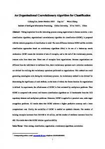
3. IMPLEMENTATION As described in the previous section, the most computation-intensive step is backprojection. This suggests that it is efficient to focus on investing computation resources in the backprojection. For this reason, we decided to off-load the backprojection step to the SPEs. Figure 3 shows the task-assigning portion of our implementation on the CBEA. First, the PPE reads the projections from the main memory and weights the projections. Next, the PPE filters the weighted data. Finally, the SPEs compute backprojections of the filtered data. In the backprojection stage, the SPEs run intensively until they finish reconstructing all of the voxels. The backprojection computation is implemented using the SPE SIMD instruction to exploit the data parallelism. For
3D Picture Filtering
Backprojection
PPE
Compute pixel locations
SPE
Packing
PPE
Backprojection
SPE
Fig. 3: The Feldkamp algorithm can be divided into three steps. The weighting and filtering stages are assigned to the PPE. The backprojection stage is assigned to the SPEs. The backprojection stage is divided into three parts. Although the core parts of the backprojection run on the SPE, the packing processing runs on the PPE. However, to implement the backprojection on the SPEs, we must consider the memory space limitations of each SPE. Each SPE contains 256 KB of memory called the local storage (LS) for both instructions and data. Since the LS cannot contain all of the data necessary for the backprojection, the projection images and the reconstructed voxels are stored in the main memory, and communicated to the LS through the ring bus. The thread in each SPE invokes a DMA transfer request to read the data and to write the results of the calculations. Data dependency is another problem. Before the backprojection computation, it is unknown which projection image pixel will be necessary for reconstructing a certain voxel. Therefore, we divided the backprojection into three parts. In the first part, the filtered projection pixel locations (u, v, β) that required for reconstruction of a certain voxel are computed by using Formulas (2)-(5). After computing the pixel locations, in the second part, the pixels P(u, v, β) are fetched from main memory and are packed. This process runs on the PPE. In the third part, the desired output individual voxels I(x, y, z) are computed by using Formula (1). 4. RESULTS We reconstructed a volume of 1283 from 64 views of 128 pixels each. The reconstruction code was executed on a 1.8 GHz CBE prototype hardware in IBM T.J. Watson Research Center in New York. Figure 4 shows comparison of execution times in backprojection step by different 2
usages of CBE (not include the weighting and the filtering.) The execution time of the core part in this figure shows the summation of the execution time of the first part and the third part of the backprojection as described the previous section. The execution time of the packing processing shows latency to fetch and pack all of the data necessary for reconstruction of a certain voxel. When the code was run by using one PPE without VMX instruction, the execution time of the core part was 97.5 seconds. On the other hand, when the code was run by using both one PPE and one SPE with SPE SIMD instructions, the execution time of the core part was 4.5 seconds. In order to measure the effect of the SPE SIMD operations, we didn't use the VMX instructions for PPE, in this measurement. Furthermore, since the execution time was measured in the PPE thread, it also includes the time of communication overhead between the PPE and SPE. These facts indicate that the SPE with SIMD operations gives more than 20 times better performance, compared to the PPE without using VMX instructions. As described before, for single precision floating point operations, since the calculation speed of the SPE can achieve eight times of the clock frequency by using SIMD instructions, SIMD operations potentially gives 8 times better performance than the case where the SIMD operations are not used, if they work effectively for the application.
Execution time [sec]
120 100 80
core
60
packing
40 20 0
PPE
PPE + 1SPE
Fig. 4: Comparison of execution time in backprojection step comparison by different usages of CBE. A volume of 1283 was reconstructed from 64 views of 1282 pixels. What is the remaining factor which boosts the performance of the SPE with SIMD further in this case? Although we haven't done a fine detailed analysis of real causes of the performance improvement in a quantitative manner, we observe another important factor for the further performance improvement in the effect of the local memory of the SPE. As discussed before, the local memory size of an SPE is 256 KB, whereas the L1 cache size of the PPE is 32 KB. For this application, the 256 KB local memory works very well and probably outperforms the effect of the L1 cache for the PPE. As the result, the
SPE with SIMD achieved more than 20 times better performance than the PPE without SIMD. On the other hand, the execution time of the packing was the 4.5 seconds in the both case because the packing was run on PPE with both cases. 5. DISCUSSION As shown in the previous section, the execution time dramatically improved by parallel use of one PPE and one SPE. This exemplified outstanding performance of SPE SIMD instructions. We observed the efficiency of SPE in the backprojection processes. However, it is expected that current program structure is inadequate to improve the overall performance in the multiple SPEs environment, since the packing processing and the core part of the backprojection are serialized. If the packing processing is able to be distributed to eight SPEs, and do pipelining both the core part of backprojection and the packing processing, the bottleneck will be resolved. When it is able to be achieved, it is expected that the execution time can be shortened to 1/8 if the latency of the packing process is hidden to the latency of the core of the backprojection. 6. CONCLUSION AND FUTURE WORK We have presented in this paper the parallelization of the Feldkamp algorithm on CBEA. The execution time dramatically improved by parallel use of one PPE and one SPE. However, this is just initial implementation. Some challenges remain in it. The biggest challenge is to parallelize the core of the backprojection and the packing processing as described in the discussion section. To parallelize the both tasks, there are further considerations: 1) how to parallelize on eight SPEs and one PPE, and 2) a double-buffering technique to hide DMA latency. In order to distribute the backprojection to eight SPEs, we should use voxel parallelism, which is based on the fact that the reconstruction of each voxel is independent of the others. In some cases, DMA latency is larger than the time required for an SPE to process the data itself. A double-buffering scheme will have a beneficial effect on elimination of the SPE idle states pending DMA completions.
ACKNOWLEDGEMENTS The author would like to thank Dr. Peter Hofstee and Mr. Barry Minor from IBM Austin for valuable discussions. REFERENCES [1]
H. P. Hiriyannaiah: “X-ray Computed Tomography for
Medical Imaging,” IEEE Signal Processing Magazine, Vol. 114, No. 2, pp. 42-59, 1997 [2] L.A. Feldkamp, L.C. Davis, and J.W. Kress, “Practical conebeam algorithm,” J. Opt. Soc. Amer., Vol. A1, pp. 612–619, 1984. [3]
A.C. Kak, M. Slaney, “Principle of computerized tomographic imaging,” New York: IEEE Press, pp. 99-107, 1988.
[4]
D. A. Reimann, V. Chaudhary, M.J. Flynn, and I.K. Sethi, “Parallel Implementation of Cone-Beam Tomography,” International Conference on Parallel Processing, II, pp. 170-173, 1996.
[5]
J. Muller-Merbach, “Simulation Of X-Ray Projections For Experimental 3D Tomography,” ISSN 1400-3902 Report No. LiTH-ISY-R-1866, March 31, 1996. http://www.cvl.isy.liu.se/Research/Tomo/take/
[6]
A. Shih, G. Wang, P. Cheng, “Fast algorithm for X-ray cone-beam microtomography,” Microscopy and Microanalysis, 7, pp.13–23, January, 2001.
[7]
I. Goddard, M. Trepanier, “High-speed cone-beam reconstruction: an embedded systems approach,” http://www.mc.com/literature/literature_files/MI468150_MercGoddard.pdf
[8]
N. Sorokin, “An FPGA-based 3D Backprojector,” Dissertation, Universität des Saarlandes, 2003.
[9]
J. A. Kahle, M. N. Day, H. P. Hofstee, C. R. Johns, T. R. Maeurer, D. Shippy, “Introduction to the Cell multiprocessor,” IBM J. RES. & DEV. Vol. 49 No. 4/5 JULY/SEPTEMBER, pp. 589 - 604, 2005.
© IBM Corporation 2005 IBM Corporation Systems and Technology Group Route 100 Somers, New York 10589 Produced in the United States of America May 2005 All Rights Reserved This document was developed for products and/or services offered in the United States. IBM may not offer the products, features, or services discussed in this document in other countries. The information may be subject to change without notice. Consult your local IBM business contact for information on the products, features and services available in your area. All statements regarding IBM future directions and intent are subject to change or withdrawal without notice and represent goals and objectives only.
IBM, the IBM logo, Power Architecture, are trademarks or registered trademarks of International Business Machines Corporation in the United States or other countries or both. A full list of U.S. trademarks owned by IBM may be found at: http://www.ibm.com/legal/copytrade.shtml. IEEE and IEEE 802 are registered trademarks in the United States, owned by the Institute of Electrical and Electronics Engineers. Other company, product, and service names may be trademarks or service marks of others. Photographs show engineering and design models. Changes may be incorporated in production models. Copying or downloading the images contained in this document is expressly prohibited without the written consent of IBM All performance information was determined in a controlled environment. Actual results may vary. Performance information is provided “AS IS” and no warranties or guarantees are expressed or implied by IBM THE INFORMATION CONTAINED IN THIS DOCUMENT IS PROVIDED ON AN "AS IS" BASIS. In no event will IBM be liable for damages arising directly or indirectly from any use of the information contained in this document.