AN INFORMED LCMV FILTER BASED ON MULTIPLE INSTANTANEOUS. DIRECTION-OF-ARRIVAL ESTIMATES. Oliver Thiergart and Emanuël A. P. Habets.
AN INFORMED LCMV FILTER BASED ON MULTIPLE INSTANTANEOUS DIRECTION-OF-ARRIVAL ESTIMATES Oliver Thiergart and Emanu¨el A. P. Habets International Audio Laboratories Erlangen∗ Am Wolfsmantel 33, 91058 Erlangen, Germany {oliver.thiergart, emanuel.habets}@audiolabs-erlangen.de ABSTRACT
and are computed based on instantaneous estimates of the model parameters. The principle advantages of parametric spatial filters are a highly flexible directional response, a comparatively strong suppression of diffuse sound and interferers, and the ability to quickly adapt to new situations. However, as shown in [20], the underlying single plane wave signal model can easily be violated in practice which strongly degrades the performance of the parametric spatial filters. In this work, we consider the problem of obtaining a desired, arbitrary spatial response for at most L sound sources being simultaneously active per time-frequency instant. We solve this problem by incorporating instantaneous parametric information about the acoustic scene into the design of a linearly constrained minimum variance (LCMV) filter resulting in an informed LCMV filter. The proposed informed spatial filter is obtained by minimizing the diffuse plus self-noise power subject to L linear constraints. In contrast to earlier works, the L constraints are based on instantaneous direction-of-arrival (DOA) estimates and the resulting responses to the L DOAs correspond to the specific desired directivity. In addition, a novel estimator for the diffuse-to-noise ratio (DNR) is developed which exhibits a sufficiently high temporal and spectral resolution to reduce both reverberation and noise. The presented results demonstrate that an optimal tradeoff between maximum white noise gain (WNG) and maximum directivity is achieved. In addition, the proposed spatial filter exhibits a short response time. The remainder of the paper is organized as follows: Section 2 formulates the problem. In Sec. 3, two existing optimal linear filters and the proposed optimal filter are described. In Sec. 4, it is shown how the L DOAs and the DNR are estimated. The performance of the proposed spatial filter is evaluated in Sec. 5. Section 6 draws the conclusions.
Extracting sound sources in noisy and reverberant conditions remains a challenging task that is commonly found in modern communication systems. In this work, we consider the problem of obtaining a desired spatial response for at most L simultaneously active sound sources. The proposed spatial filter is obtained by minimizing the diffuse plus self-noise power at the output of the filter subject to L linear constraints. In contrast to earlier works, the L constraints are based on instantaneous narrowband direction-of-arrival estimates. In addition, a novel estimator for the diffuse-to-noise ratio is developed that exhibits a sufficiently high temporal and spectral resolution to achieve both dereverberation and noise reduction. The presented results demonstrate that an optimal tradeoff between maximum white noise gain and maximum directivity is achieved. Index Terms— microphone array processing, optimal beamforming, diffuse-to-noise ratio estimation 1. INTRODUCTION Extracting sound sources in noisy and reverberant conditions is commonly found in modern communication systems. In the last four decades, a large variety of spatial filtering techniques have been proposed to accomplish this task. Existing spatial filters are optimal when the assumed signal model is valid and when the information required to compute the filters is accurate. In practice, however, the signal model is often violated and estimating the required information becomes a major challenge. Existing spatial filters can be broadly classified into linear spatial filters [1–4] and parametric spatial filters [5–8]. In general, linear spatial filters require an estimate of the propagation vector(s) or the second-order statistics (SOS) of the desired source(s) plus the SOS of the interference. Some spatial filters are designed to extract a single source signal (either reverberant or dereverberated) [9–16], while others have been designed to extract the sum of two or more reverberant source signals [17–19]. The aforementioned methods require prior knowledge of the direction of the desired source(s) or a period in which only the desired sources are active (either separately or simultaneously). A drawback of these methods is the inability to adapt sufficiently quickly to new situations (e. g., source movements, competing speakers that become active when the desired source is active). Parametric spatial filters are often based on a relatively simple signal model (i. e., the received signal in the timefrequency domain consists of a single plane wave plus diffuse sound)
2. PROBLEM FORMULATION Let us consider an uniform linear array (ULA) of M omnidirectional microphones located at d1...M . For each time-frequency instant we assume a sound field composed of L < M plane waves (directional sound) propagating in an isotropic and spatially homogenous diffuse sound field. The microphone signals x(k, n) = [X(k, n, d1 ) . . . X(k, n, dM )]T at frequency index k and time index n can be written as x(k, n) =
xl (k, n) + xd (k, n) + xn (k, n),
(1)
l=1
where xl (k, n) = [Xl (k, n, d1 ) . . . Xl (k, n, dM )]T contains the microphone signals that are proportional to the sound pressure of the l-th plane wave, xd (k, n) is the measured diffuse field, and xn (k, n) is the microphone self-noise.
∗ A joint institution of the University Erlangen-Nuremberg and Fraunhofer IIS, Germany
978-1-4799-0356-6/13/$31.00 ©2013 IEEE
L X
659
ICASSP 2013
0
=
L X
Φl (k, n) + Φd (k, n) + Φn (k, n),
|G(k, ϕ)|2 [dB]
Assuming the three components in (1) are mutually uncorrelated, we can express the power spectral density (PSD) matrix of the microphone signals as n o Φ(k, n) = E x(k, n) xH (k, n)
−5 −10
G1 G2 ϕA ϕB
−15 −20
(2)
−90
−45
0
l=1
45
90
DOA ϕ [◦ ]
with
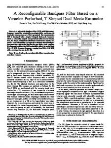
Fig. 1. Two arbitrary directivity functions & source positions Φd (k, n) = φd (k, n) Γd (k), Φn (k, n) = φn (k, n) I.
(3) (4)
3. OPTIMAL SPATIAL FILTERS
Here, I is an identity matrix, φn (k, n) is the expected power of the microphone self-noise, which is identical for all microphones, and φd (k, n) is the expected power of the diffuse field, which can vary rapidly across time and frequency. The ij-th element of the coherence matrix Γd (k), denoted by γij (k), is the diffuse field coherence between microphone i and j. For instance for a spherically isotropic diffuse field, we have γij (k) = sinc(κ rij ) [21] with wavenumber κ and rij = ||dj − di ||. The directional sound xl (k, n) in (1) can be written as xl (k, n) = a(k, ϕl ) Xl (k, n, d1 ),
3.1. Existing Spatial Filters While the PSD φn (k, n) can be estimated during periods of silence, φd (k, n) is commonly assumed unknown and unobservable. We therefore consider two existing spatial filters that can be computed without this knowledge. The first spatial filter is known as a delay-and-sum beamformer and minimizes the self-noise power at the filter’s output (i. e., maximizes the WNG) [1]. The optimal weight vector that minimizes the mean squared error (MSE) between (7) and (8) subject to (9) is then obtained by
(5)
where ϕl (k, n) is the DOA of the l-th plane wave (ϕ = 0 denoting the array broadside) and a(k, ϕl ) = [a1 (k, ϕl ) . . . aM (k, ϕl )]T is the propagation vector. The i-th element of a(k, ϕl ), � ai (k, ϕl ) = exp κ ri sin ϕl (k, n) , (6)
wn = arg min wH Φn (k, n) w w | {z }
L X
G(k, ϕl ) Xl (k, n, d1 ),
(10)
There exists a closed-form solution to (10) [1] that allows a fast computation of wn . It should be noted that this filter does not necessarily provide the largest directivity index (DI). The second spatial filter is known as the robust superdirective (SD) beamformer and minimizes the diffuse sound power at the filter’s output (i. e., maximizes the DI) with a lower-bound on the WNG [22]. The lower-bound on the WNG increases the robustness to errors in the propagation vector and limits the amplification of the self-noise [22]. The optimal weight vector that minimizes the MSE between (7) and (8) subject to (9) and satisfies the lower-bound on the WNG is then obtained by
describes the phase shift of the l-th plane wave from the first to the i-th microphone. Note that ri = ||di − d1 || is equal to the distance between the first and the i-th microphone. The aim of the paper is to filter the microphone signals x(k, n) such that directional sounds arriving from specific spatial regions are attenuated or amplified as desired, while the diffuse sound and microphone self-noise are suppressed. The desired signal can therefore be expressed as Y (k, n) =
s. t. (9).
wH w
(7)
l=1
wd = arg min wH Φd (k, n) w w | {z }
where G(k, ϕ) is a real-valued arbitrary directivity function which can be frequency dependent. Figure 1 shows the magnitude of two example directivities G1 (k, ϕ) and G2 (k, ϕ). When using G1 (k, ϕ) (solid line), we attenuate directional sound arriving from ϕ < 45◦ by 21 dB while directional sound from other directions is not attenuated. In principle, one can design arbitrary directivities, even functions such as G2 (k, ϕ) (dashed line). Moreover, G(k, ϕ) can be designed time variant, e. g., to extract moving or emerging sound sources once they have been localized. An estimate of the signal Y (k, n) is obtained by a linear combination of the microphone signals x(k, n), i. e., Yˆ (k, n) = wH (k, n) x(k, n),
l ∈ {1, 2, . . . , L}.
(11)
and subject to a quadratic constraint wH w < β. The parameter β −1 defines the minimum WNG and determines the achievable DI of the filter. In practice, it is often difficult to find an optimal trade-off between a sufficient WNG in low signal-to-noise ratio (SNR) situations, and a sufficiently high DI in high SNR situations. Moreover, solving (11) leads to a non-convex optimization problem due to the quadratic constraint, which is time-consuming to solve. This is especially problematic in our application, since the complex weight vector needs to be recomputed for each k and n due to the time-varying constraints (9).
(8)
where w(k, n) is a complex weight vector of length M . It follows from (5) and (7) that w(k, n) has to satisfy the linear constraints wH (k, n) a(k, ϕl ) = G(k, ϕl ),
s. t. (9)
wH Γd (k,n) w
3.2. Proposed Spatial Filters
(9)
The proposed spatial filter combines the benefits of the spatial filters in the previous subsection, i. e., providing a high DI in situations with high DNR, and a high WNG otherwise. The spatial filter is only linearly constrained, which allows a fast computation of the weights.
Moreover, the diffuse sound power and self-noise power at the filter’s output has to be minimized. The corresponding optimal weight vector w(k, n) is derived in the next section. In the following, the dependency of the weights w(k, n) on k and n is omitted for brevity.
660
The optimal weights w(k, n) to solve our problem in (8) are found by minimizing the sum of the self-noise power and diffuse sound power at the filter’s output, i. e., s. t. (9).
w
frequency [kHz]
wnd = arg min wH [Φd (k, n) + Φn (k, n)] w
40
8
(12)
Using (3) and (4), the optimization problem can be expressed as
7 30
6 5
20
4 10
3 2
0
1
wnd = arg min w w
H
[Ψ(k, n) Γd (k) + I] w | {z }
s. t. (9),
(13)
0
0.5
1
φd (k, n) φn (k, n)
is the time-varying input DNR at the array microphones. The solution to (13) given the constraints (9) is [23] h i−1 g, (15) wnd = J−1 A AH J−1 A
5
w a(k, ϕ0 ) = 1.
2
(16)
(17)
l
1
1.5
2
2.5
3
5.1. Time-Invariant Directional Constraints
H H wΨ Φ(k, n) wΨ = φd (k, n) wΨ Γd (k) wΨ
For this simulation, we assume prior knowledge about the two source positions ϕA and ϕB . In all processing steps we used ϕ1 (k, n) = ϕA and ϕ2 (k, n) = ϕB . Therefore, the directional constraints in (9) and (17) do not vary over time. Figure 2 shows the true and estimated DNR Ψ(k, n) as a function of time and frequency. We obtain a relatively high DNR during
(20)
The input DNR can now be computed with (14) and (20), i. e., H H wΨ Φ(k, n) wΨ − φn (k, n) wΨ wΨ H φn (k, n) wΨ Γd (k) wΨ .
0.5
Let us assume L = 2 plane waves in the model in (1) and an ULA with M = 4 microphones with an inter-microphone spacing of 3 cm. A reverberant shoebox room (7.0 × 5.4 × 2.4 m3 , RT60 ≈ 380 ms) was simulated using the source-image method [26, 27] with two speech sources at ϕA = 86◦ and ϕB = 11◦ , respectively (distance 1.75 m, cf. Fig. 1). The signals consisted of 0.6 s silence followed by double talk. White Gaussian noise was added to the microphone signals resulting in a segmental signal-to-noise ratio (SSNR) of 26 dB. The sound was sampled at 16 kHz and transformed into the time-frequency domain using a 512-point STFT with 50% overlap. We consider the directivity function G1 (ϕ) in Fig. 1, i. e., we aim at extracting source A without distortions while attenuating the power of source B by 21 dB. We compare the two spatial filters in Sec. 3.1 and the proposed spatial filter in Sec. 3.2. For the robust SD beamformer (11), we set the minimum WNG to −12 dB. For the proposed spatial filter (13), we estimate the DNR Ψ(k, n) as explained in Sec. 4. The self-noise power φn (k, n) is computed from the silent signal part at the beginning. The expectation in (2) is approximated by a recursive temporal average over τ = 50 ms.
where ϕ ∈ [− π2 , π2 ]. Given the weights wΨ , the output power of the additional spatial filter is given by
Ψ(k, n) =
0
5. EXPERIMENTAL RESULTS
(18)
H + φn (k, n) wΨ wΨ .
10
3
The required expected power of the microphone self-noise φn (k, n) can for example be estimated during silence assuming that the power is constant over time. Note that the proposed DNR estimator does not necessarily provide the lowest estimation variance in practice due to the chosen optimization criteria (16), but provides unbiased results.
Constraint (18) ensures non-zero weights wΨ . The propagation vector a(k, ϕ0 ) corresponds to a specific direction ϕ0 (k, n) being different from the DOAs ϕl (k, n) of the L plane waves. In the following, we choose for ϕ0 (k, n) the direction which has the largest distance to all ϕl (k, n), i. e., � ϕ0 (k, n) = arg max min |ϕ − ϕl (k, n)| , (19) ϕ
20
4
Fig. 2. True and estimated DNR Ψ(k, n). The two marked areas indicate respectively a silent and active part of the signal.
subject to l ∈ {1, 2, . . . , L},
30
6
−10
Several parameters need to be estimated for the proposed approach in Sec. 3.2. The DOAs ϕl (k, n) of the L plane waves can be obtained with well-known narrowband DOA estimators such as ESPRIT [24] or root MUSIC [25]. In the following, we discuss the estimation of the input DNR Ψ(k, n). To estimate Ψ(k, n), we propose to use an additional spatial filter which cancels the L plane waves such that only diffuse sound is captured. The weights of this spatial filter are found by maximizing the WNG of the array, i. e.,
H
40
time [s] (b) Estimated Ψ(k, n) [dB]
4. PARAMETER ESTIMATION
wH a(k, ϕl ) = 0,
−10
7
0
w
3
1
where A(k, n) = [a(k, ϕ1 ) . . . a(k, ϕL )] contains the propagation vectors for the L plane waves. The corresponding gains are given by g(k, n) = [G(k, ϕ1 ) . . . G(k, ϕL )]T . The estimation of Ψ(k, n) is discussed in the next section.
wΨ = arg min wH w
2.5
8
(14)
frequency [kHz]
Ψ(k, n) =
2
time [s] (a) True Ψ(k, n) [dB]
=J(k,n)
where
1.5
(21)
661
90
wn wd wnd wnd
9
frequency [kHz]
DI [dB]
12
6
3
5 45
4 3
0
2 −45 1 0
1
0.5
1
0
2
2.5
3
−90
0
wn wd wnd wnd
frequency [kHz]
WNG [dB]
6
1.5
time [s] (a) DOA ϕ1 (k, n) [◦ ]
frequency [kHz] (a) Mean DI
−6 −12 −18
5 −5 4 3
−10
2
−15
1 −20
1
0
frequency [kHz] (b) Mean WNG
0.5
1
1.5
2
2.5
3
time [s] (b) |G(k, ϕ1 )|2 [dB]
Fig. 3. DI and WNG of the spatial filters in Sec. 3. For wd , the minimum WNG was set to −12 dB to make the spatial filter robust against the microphone self-noise.
Fig. 4. Estimated DOA ϕ1 (k, n) and resulting gains G(k, ϕ1 ) Table 1 summarizes the overall performance of the spatial filters in terms of signal-to-interference ratio (SIR), signal-to-reverberation ratio (SRR), and SSNR at the filter’s output. In terms of SIR and SRR (source separation, dereverberation), the proposed approach (wnd ) and the robust SD beamformer (wd ) provide the highest performance. However, the SSNR of the proposed wnd is 6 dB higher than the SSNR of wd , which represented a clearly audible benefit. The best performance in terms of SSNR is obtained using wn . In terms of PESQ, wnd and wd outperform wn . Using instantaneous directional constraints (as in this section) instead of timeinvariant constrains (as in Sec. 5.1, values in brackets) mainly reduced the achievable SIR, but provides a fast adaption in case of varying source positions. Note that the computation time of all required complex weights per time frame was larger than 80 s for wd (CVX toolbox [28, 29]) and smaller than 0.08 s for the proposed approach (MATLAB R2012b, MacBook Pro 2008).
speech activity due to the reverberant environment. The estimated DNR in Fig. 2(b) possesses a limited temporal resolution due to the incorporated temporal averaging process. Nevertheless, the Ψ(k, n) estimates are sufficiently accurate as shown by the following results. Figure 3(a) depicts the mean DI for wn and wd (which are both signal-independent), and for the proposed spatial filter wnd (which is signal-dependent). For the proposed spatial filter, we show the DI for a silent part of the signal and during speech activity [both signal parts marked in Fig. 2(b)]. During silence, the proposed spatial filter (dashed line wnd ) provides the same low DI as wn . During speech activity (solid line wnd ), the obtained DI is as high as for the robust SD beamformer (wd ). Figure 3(b) shows the corresponding WNGs. During silence, the proposed spatial filter (dashed line wnd ) achieves a high WNG, while during signal activity, the WNG is relatively low. In general, Fig. 3 shows that the proposed spatial filter combines the advantages of both existing spatial filters: during silent parts, a maximum WNG is provided leading to a minimal self-noise amplification, i. e., high robustness. During signal activity and high reverberation, where the self-noise is usually masked, a high DI is provided (at cost of a low WNG) leading to an optimal reduction of the diffuse sound. In this case, even rather small WNGs are tolerable. Note that for higher frequencies (f > 5 kHz), all spatial filters perform nearly identically since the coherence matrix Γd (k) in (11) and (13) is approximately equal to an identity matrix.
6. CONCLUSIONS An informed linearly constrained minimum variance filter was proposed that provides a desired spatial response for L sources being simultaneously active for each time and frequency in a noisy and reverberant environment. The filter exploits instantaneous information on the direction-of-arrival of L plane waves and on the diffuse-tonoise ratio (DNR) at the filter input. The DNR information allows us to design a filter that maximizes the white noise gain when the DNR is low, and the directivity index when the DNR is high. Simulations results demonstrate the practical applicability of the proposed filter and DNR estimator.
5.2. Instantaneous Directional Constraints For this simulation, we assume that no a priori information on ϕA and ϕB is available. The DOAs ϕ1 (k, n) and ϕ2 (k, n) are estimated with ESPRIT. Thus, the constraints (9) vary across time. Only for the robust SD beamformer (wd ) we use a single and time-invariant constraint (9) corresponding to a fixed look direction of ϕA = 86◦ . This beamformer serves as a reference. Figure 4 shows the estimated DOA ϕ1 (k, n) and resulting gain |G(k, ϕ1 )|2 . The arriving plane wave is not attenuated if the DOA is inside the spatial window in Fig. 1 (solid line). Otherwise, the power of the wave is attenuated by 21 dB.
∗ wn wd wnd
SIR [dB] 11 (11) 21 (32) 26 (35) 25 (35)
SRR [dB] −7 (−7) −2 (−3) 0 (−1) 1 (−1)
SSNR [dB] 26 (26) 33 (31) 22 (24) 28 (26)
PESQ 1.5 (1.5) 2.0 (1.7) 2.1 (2.0) 2.1 (2.0)
Table 1. Performance of all spatial filters [∗ unprocessed]. Values in brackets refer to Sec. 5.1, otherwise Sec. 5.2. The signals were A-weighted before computing the SIR, SRR, and SSNR.
662
7. REFERENCES [1] J. Benesty, J. Chen, and Y. Huang, Microphone Array Signal Processing. Berlin, Germany: Springer-Verlag, 2008.
[15] E. A. P. Habets and J. Benesty, “Joint dereverberation and noise reduction using a two-stage beamforming approach,” in Proc. Hands-Free Speech Communication and Microphone Arrays (HSCMA), 2011, pp. 191–195.
[2] S. Doclo, S. Gannot, M. Moonen, and A. Spriet, “Acoustic beamforming for hearing aid applications,” in Handbook on Array Processing and Sensor Networks, S. Haykin and K. Ray Liu, Eds. Wiley, 2008, ch. 9.
[16] M. Taseska and E. A. P. Habets, “MMSE-based blind source extraction in diffuse noise fields using a complex coherencebased a priori SAP estimator,” in Proc. Intl. Workshop Acoust. Signal Enhancement (IWAENC), Sep. 2012.
[3] S. Gannot and I. Cohen, “Adaptive beamforming and postfiltering,” in Springer Handbook of Speech Processing, J. Benesty, M. M. Sondhi, and Y. Huang, Eds. Springer-Verlag, 2008, ch. 47.
[17] S. Affes, S. Gazor, and Y. Grenier, “An algorithm for multisource beamforming and multitarget tracking,” Signal Processing, IEEE Transactions on, vol. 44, no. 6, pp. 1512–1522, June 1996.
[4] J. Benesty, J. Chen, and E. A. P. Habets, Speech Enhancement in the STFT Domain, ser. SpringerBriefs in Electrical and Computer Engineering. Springer-Verlag, 2011.
[18] G. Reuven, S. Gannot, and I. Cohen, “Dual source transferfunction generalized sidelobe canceller,” IEEE Trans. Speech Audio Process., vol. 16, no. 4, pp. 711–727, May 2008.
[5] I. Tashev, M. Seltzer, and A. Acero, “Microphone array for headset with spatial noise suppressor,” in Proc. Ninth International Workshop on Acoustic, Echo and Noise Control (IWAENC), Eindhoven, The Netherlands, 2005.
[19] S. Markovich, S. Gannot, and I. Cohen, “Multichannel eigenspace beamforming in a reverberant noisy environment with multiple interfering speech signals,” IEEE Trans. Audio, Speech, Lang. Process., vol. 17, no. 6, pp. 1071–1086, Aug. 2009.
[6] M. Kallinger, G. Del Galdo, F. Kuech, D. Mahne, and R. Schultz-Amling, “Spatial filtering using directional audio coding parameters,” in Proc. IEEE Intl. Conf. on Acoustics, Speech and Signal Processing (ICASSP), Apr. 2009, pp. 217– 220.
[20] O. Thiergart and E. A. P. Habets, “Sound field model violations in parametric spatial sound processing,” in Proc. Intl. Workshop Acoust. Signal Enhancement (IWAENC), Sep. 2012. [21] R. K. Cook, R. V. Waterhouse, R. D. Berendt, S. Edelman, and M. C. Thompson Jr., “Measurement of correlation coefficients in reverberant sound fields,” The Journal of the Acoustical Society of America, vol. 27, no. 6, pp. 1072–1077, 1955.
[7] M. Kallinger, G. Del Galdo, F. Kuech, and O. Thiergart, “Dereverberation in the spatial audio coding domain,” in Audio Engineering Society Convention 130, London UK, May 2011. [8] G. Del Galdo, O. Thiergart, T. Weller, and E. A. P. Habets, “Generating virtual microphone signals using geometrical information gathered by distributed arrays,” in Proc. Hands-Free Speech Communication and Microphone Arrays (HSCMA), Edinburgh, United Kingdom, May 2011.
[22] H. Cox, R. M. Zeskind, and M. M. Owen, “Robust adaptive beamforming,” IEEE Trans. Acoust., Speech, Signal Process., vol. 35, no. 10, pp. 1365–1376, Oct. 1987. [23] O. L. Frost, III, “An algorithm for linearly constrained adaptive array processing,” Proc. IEEE, vol. 60, no. 8, pp. 926–935, Aug. 1972.
[9] S. Nordholm, I. Claesson, and B. Bengtsson, “Adaptive array noise suppression of handsfree speaker input in cars,” IEEE Trans. Veh. Technol., vol. 42, no. 4, pp. 514–518, Nov. 1993.
[24] R. Roy and T. Kailath, “ESPRIT-estimation of signal parameters via rotational invariance techniques,” Acoustics, Speech and Signal Processing, IEEE Transactions on, vol. 37, no. 7, pp. 984–995, July 1989.
[10] O. Hoshuyama, A. Sugiyama, and A. Hirano, “A robust adaptive beamformer for microphone arrays with a blocking matrix using constrained adaptive filters,” IEEE Trans. Signal Process., vol. 47, no. 10, pp. 2677–2684, Oct. 1999.
[25] B. Rao and K. Hari, “Performance analysis of root-music*,” in Signals, Systems and Computers, 1988. Twenty-Second Asilomar Conference on, vol. 2, 1988, pp. 578–582.
[11] S. Gannot, D. Burshtein, and E. Weinstein, “Signal enhancement using beamforming and nonstationarity with applications to speech,” IEEE Trans. Signal Process., vol. 49, no. 8, pp. 1614–1626, Aug. 2001.
[26] J. B. Allen and D. A. Berkley, “Image method for efficiently simulating small-room acoustics,” J. Acoust. Soc. Am., vol. 65, no. 4, pp. 943–950, Apr. 1979.
[12] W. Herbordt and W. Kellermann, “Adaptive beamforming for audio signal acquisition,” in Adaptive Signal Processing: Applications to real-world problems, ser. Signals and Communication Technology, J. Benesty and Y. Huang, Eds. Berlin, Germany: Springer-Verlag, 2003, ch. 6, pp. 155–194.
[27] E. A. P. Habets. (2008, May) Room impulse response (RIR) generator. [Online]. Available: http://home.tiscali.nl/ehabets/rirgenerator.html [28] I. CVX Research, “CVX: Matlab software for disciplined convex programming, version 2.0 beta,” http://cvxr.com/cvx, September 2012.
[13] R. Talmon, I. Cohen, and S. Gannot, “Convolutive transfer function generalized sidelobe canceler,” IEEE Trans. Audio, Speech, Lang. Process., vol. 17, no. 7, pp. 1420–1434, Sep. 2009.
[29] M. Grant and S. Boyd, “Graph implementations for nonsmooth convex programs,” in Recent Advances in Learning and Control, ser. Lecture Notes in Control and Information Sciences, V. Blondel, S. Boyd, and H. Kimura, Eds. Springer-Verlag Limited, 2008, pp. 95–110.
[14] A. Krueger, E. Warsitz, and R. Haeb-Umbach, “Speech enhancement with a GSC-like structure employing eigenvectorbased transfer function ratios estimation,” IEEE Trans. Audio, Speech, Lang. Process., vol. 19, no. 1, pp. 206–219, Jan. 2011.
663