An IPsec Compatible Implementation of DBRA and IP-ABR by Nicol´as Sherwood Droz
A Thesis Submitted to the Faculty of the WORCESTER POLYTECHNIC INSTITUTE in partial fulfillment of the requirements for the Degree of Master of Science in Electrical and Computer Engineering by May 2005
APPROVED: Prof. David Cyganski, Major Advisor Prof. Brian King Prof. John Orr
Abstract Satellites are some of the most difficult links to exploit in a Quality of Service (QoS) sensitive network, largely due to their high latency, variable-bandwidth and low-bandwidth nature. Central management of shared links has been shown to provide efficiency gains and enhanced QoS by effectively allocating resources according to reservations and dynamic resource availability. In a modern network, segregated by secure gateways and tunnels such as provided by IPsec, central management appears impossible to implement due to the barriers created between a global Dynamic Bandwidth Resource Allocation (DBRA) system and the mediators controlling the individual flows. This thesis explores and evaluates various through-IPsec communications techniques aimed at providing a satellite-to-network control channel, while maintaining data security for all communications involved.
iii
Acknowledgements To my family: Edna, Tim and Maia, who taught me the value of education, and above all else to follow my heart... I have, and always will.
To my sponsors: I would like to thank Raytheon’s Network Centric Systems Division for sponsoring this project and my Degree of Masters of Science. Specifically I would like to thank Jim McGrath: by far the friendliest, most helpful and interesting liaison one could ever hope to have.
To my trusted MVL associates: Thanks to Ben, David and Nick, for providing countless hours of refreshing “creative-time”, in the lab, and elsewhere. I am particularly grateful to David, who became my Linux oracle, and who selflessly spent his time helping and debugging everything from TCP sockets to hard disk geometries for legitimate and otherwise interesting purposes.
To my committee members: A big thank you goes to my committee members Professor John Orr and Professor Brian King who took on the dreaded last minute thesis crunch, I don’t know how you guys help us demented students for a living!
To my advisor: I am indebted to Professor David Cyganski; teacher, advisor and overall great story teller. He has spent more time than any sane person could making this thesis into a readable document, and making me into a good student and research assistant. I will never forget my days with Beast, Revanche and Prof. X on the bridge of the MVL.
iv
Contents List of Figures
vi
List of Tables
viii
1 Introduction
1
2 Background 3 2.1 Satellite Channels and DBRA . . . . . . . . . . . . . . . . . . . . . . . . . . 4 2.2 IP-ABR Background . . . . . . . . . . . . . . . . . . . . . . . . . . . . . . . 4 2.2.1 Advantages . . . . . . . . . . . . . . . . . . . . . . . . . . . . . . . . 6 2.3 IPsec Background . . . . . . . . . . . . . . . . . . . . . . . . . . . . . . . . 7 2.3.1 Authentication Header . . . . . . . . . . . . . . . . . . . . . . . . . . 7 2.3.2 Encapsulating Security Payload (ESP) . . . . . . . . . . . . . . . . . 8 2.3.3 Internet Security Association & Key Management Protocol (ISAKMP) 9 2.4 The DBRA and IPsec Conflict . . . . . . . . . . . . . . . . . . . . . . . . . 10 3 Explored Methods 3.1 ICMP Piggybacking . . . . . . . . . 3.2 Packet Morse Code . . . . . . . . . . 3.3 On-rack Middleman . . . . . . . . . 3.4 ECN-X . . . . . . . . . . . . . . . . 3.4.1 ECN . . . . . . . . . . . . . . 3.4.2 ECN Expropriation (ECN-X) 3.5 DEAC . . . . . . . . . . . . . . . . . 3.5.1 Credit Bucket DBRA Control 3.5.2 DEAC Conclusions . . . . . . 3.6 POM . . . . . . . . . . . . . . . . . . 3.6.1 Doubly Encrypted POM . . . 4 Implementations 4.1 ECN-X . . . . . . . . . . . . . 4.1.1 ECN Technical Details . 4.1.2 ECN/IPsec Interaction . 4.1.3 Software Tools . . . . .
. . . .
. . . .
. . . .
. . . . . . . . . . . . . . .
. . . . . . . . . . . . . . .
. . . . . . . . . . . . . . .
. . . . . . . . . . . . . . .
. . . . . . . . . . . . . . .
. . . . . . . . . . . . . . .
. . . . . . . . . . . . . . .
. . . . . . . . . . . . . . .
. . . . . . . . . . . . . . .
. . . . . . . . . . . . . . .
. . . . . . . . . . . . . . .
. . . . . . . . . . . . . . .
. . . . . . . . . . . . . . .
. . . . . . . . . . . . . . .
. . . . . . . . . . . . . . .
. . . . . . . . . . . . . . .
. . . . . . . . . . . . . . .
. . . . . . . . . . . . . . .
. . . . . . . . . . . . . . .
. . . . . . . . . . . . . . .
. . . . . . . . . . . . . . .
. . . . . . . . . . .
13 14 15 17 19 19 20 21 22 25 25 27
. . . .
30 30 30 31 33
v . . . . . . . .
42 49 49 51 52 54 60 62
. . . . . . .
64 64 64 65 66 67 69 69
6 Results 6.1 ECN-X . . . . . . . . . . . . . . . . . . . . . . . . . . . . . . . . . . . . . . 6.2 POM . . . . . . . . . . . . . . . . . . . . . . . . . . . . . . . . . . . . . . . .
70 70 77
7 Conclusion
82
A Abbreviations
85
B Netfilter nf getinfo() Declaration
87
C KAME IPsec Configuration Files C.1 ipsec.conf . . . . . . . . . . . . . . . . . . . . . . . . . . . . . . . . . . . . . C.2 racoon.conf . . . . . . . . . . . . . . . . . . . . . . . . . . . . . . . . . . . . C.3 psk.txt . . . . . . . . . . . . . . . . . . . . . . . . . . . . . . . . . . . . . . .
90 90 90 93
Bibliography
94
4.2
4.1.4 The ECN-X Modules . . . POM . . . . . . . . . . . . . . . . 4.2.1 POM Reordering Theory 4.2.2 POM/IPsec interaction . 4.2.3 Software Tools . . . . . . 4.2.4 POM Sender . . . . . . . 4.2.5 POM Receiver . . . . . . 4.2.6 POM Control . . . . . . .
5 Testing 5.1 Operations Testbed . . . . . . . . 5.1.1 Satellite Link Emulation . 5.1.2 IPsec Encryption Tunnel 5.1.3 IP-ABR Proxy . . . . . . 5.1.4 Hardware Configuration . 5.1.5 TCP Traffic Generator . . 5.1.6 Test Procedure . . . . . .
. . . . . . . . . . . . . . .
. . . . . . . . . . . . . . .
. . . . . . . . . . . . . . .
. . . . . . . . . . . . . . .
. . . . . . . . . . . . . . .
. . . . . . . . . . . . . . .
. . . . . . . . . . . . . . .
. . . . . . . . . . . . . . .
. . . . . . . . . . . . . . .
. . . . . . . . . . . . . . .
. . . . . . . . . . . . . . .
. . . . . . . . . . . . . . .
. . . . . . . . . . . . . . .
. . . . . . . . . . . . . . .
. . . . . . . . . . . . . . .
. . . . . . . . . . . . . . .
. . . . . . . . . . . . . . .
. . . . . . . . . . . . . . .
. . . . . . . . . . . . . . .
. . . . . . . . . . . . . . .
. . . . . . . . . . . . . . .
. . . . . . . . . . . . . . .
. . . . . . . . . . . . . . .
vi
List of Figures 2.1 2.2 2.3 2.4
An IP-ABR Simulation Landscape. . . . . . . . . Throughput of 32 TCP Flows over 8 minutes. . . Black to Red Communication is Prohibited. . . . Black and Red labels are used to refer to security
. . . . . . . . . . . . . . . . . . divisions.
. . . .
. . . .
. . . .
. . . .
. . . .
. . . .
. . . .
. . . .
. . . .
5 6 11 11
3.1 3.2 3.3 3.4 3.5 3.6 3.7 3.8 3.9 3.10 3.11
Single IPsec control setup. . . . . . . . . . . . . . . . . . . Piggybacking on ICMPs through IPsec. . . . . . . . . . . Marking a packet flow to send a patterned message. . . . Individual flow routing identification. . . . . . . . . . . . . Two IPsec machines provide two secure channels. . . . . . Template for an IP header, where the ECN bits reside. . . Global DEAC scheme with Credit Bucket DBRA control. Credit Bucket DBRA Control inside the DEAC layout. . . Packet Order Modulation through IPsec. . . . . . . . . . . Multiple flow reordering presents a more difficult problem. Doubly Encrypted POM provides complete security. . . .
. . . . . . . . . . .
. . . . . . . . . . .
. . . . . . . . . . .
. . . . . . . . . . .
. . . . . . . . . . .
. . . . . . . . . . .
. . . . . . . . . . .
. . . . . . . . . . .
. . . . . . . . . . .
14 15 16 17 18 20 23 24 27 27 29
4.1 4.2 4.3 4.4 4.5 4.6 4.7 4.8 4.9 4.10 4.11 4.12
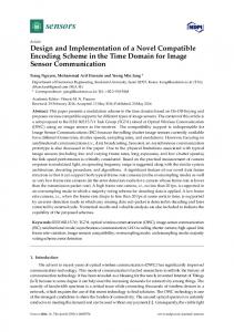
IPsec interaction with the ECN bits. . . . . . . . . . . . . . . . . . ECN-X sender flowchart. . . . . . . . . . . . . . . . . . . . . . . . . ECN-X receiver flowchart. . . . . . . . . . . . . . . . . . . . . . . . Netfilter hook packet traversal. (used with artist consent) . . . . . Sample ECN-X message using codepoints. . . . . . . . . . . . . . . Software component diagram of ECN-X sender. . . . . . . . . . . . Software component diagram of ECN-X receiver. . . . . . . . . . . Example IPsec sliding window. . . . . . . . . . . . . . . . . . . . . Software component diagram of POM sender. . . . . . . . . . . . . Userspace queue reordering using libipq. . . . . . . . . . . . . . . . Software component diagram of POM receiver. . . . . . . . . . . . An example permutation message extracted from a sequence flow.
. . . . . . . . . . . .
. . . . . . . . . . . .
. . . . . . . . . . . .
. . . . . . . . . . . .
. . . . . . . . . . . .
32 34 35 38 41 43 44 52 55 57 61 62
5.1 5.2
Complete testbed using five PCs. . . . . . . . . . . . . . . . . . . . . . . . . Routing configuration for the testbed. . . . . . . . . . . . . . . . . . . . . .
67 68
6.1
ECN-X testbed arrangement. . . . . . . . . . . . . . . . . . . . . . . . . . .
71
. . . . . . . . . . .
vii 6.2 6.3 6.4 6.5 6.6 6.7 6.8 6.9
10 unchecked TCP flows over a satellite T1 link (1.536Mbps, 900ms delay). 10 IP-ABR controlled TCP flows plus ECN-X allocation. . . . . . . . . . . Delay and jitter effects of software encryption. . . . . . . . . . . . . . . . . Controlled TCP bandwidth allocations using ECN-X. . . . . . . . . . . . . POM testbed variation with pipsecd. . . . . . . . . . . . . . . . . . . . . . . The effect of processing power on testing. . . . . . . . . . . . . . . . . . . . POM-controlled bandwidth allocation variations. . . . . . . . . . . . . . . . POM-controlled bandwidth allocation using fast transitions. . . . . . . . . .
73 74 75 76 77 78 80 81
viii
List of Tables 2.1 2.2
The Authentication Header Format. . . . . . . . . . . . . . . . . . . . . . . The ESP Header Format. . . . . . . . . . . . . . . . . . . . . . . . . . . . .
8 9
4.1 4.2
The ECN Codepoint Definitions. . . . . . . . . . . . . . . . . . . . . . . . . Exponential vs. Factorial Growth. . . . . . . . . . . . . . . . . . . . . . . .
31 50
5.1
NISTnet emulator configuration. . . . . . . . . . . . . . . . . . . . . . . . .
65
6.1 6.2
ECN-X testbed details. . . . . . . . . . . . . . . . . . . . . . . . . . . . . . POM testbed details. . . . . . . . . . . . . . . . . . . . . . . . . . . . . . . .
71 79
1
Chapter 1
Introduction Establishing and maintaining Internet connections with specific Quality of Service (QoS) guarantees is generally challenging but is especially so given low bandwidth, high latency and variable rate channels such as those found on satellite links. Previous research has demonstrated effective means for dynamically assigning and regulating bandwidth utilization via proxy servers by manipulation of basic TCP parameters. Management of such proxy servers is given to Dynamic Bandwidth Resource Allocation (DBRA) systems which monitor satellite channels and resolve QoS requests centrally. Unfortunately the use of IPsec for secure communications introduces a barrier between the proxies and the DBRA system which on first appearances cannot be breached without compromising security. We endeavored, however, to achieve this communication without a full reconstruction of the secure network topology. The project explored the IPsec standard thoroughly to gain a deeper understanding of the various restrictions and permissions surrounding a secure network. Within this scope several novel communication ideas were developed and these notions further led to complete solutions involving proxy servers within full DBRA schemes. In the course of the research various techniques were proposed, evaluated and herein discussed, which interact with IPsec in unique ways to move information across secure gateways. In the end two techniques were devised and implemented which successfully demonstrate through-IPsec communication and full DBRA bandwidth/QoS control without compromising security.
2 In the following chapter we begin by exploring the background work done in the previous projects, which lead to the current work discussed herein. Specifically the IP-ABR concept is examined and its relationship to the DBRA system, which leads directly to our problem statement. In Chapter 3 we explore high-level solutions to the our communications dilemma. Each of the methods discussed provides some unique perspective on the problem; though they are not all implemented, each still contributes some important idea to our final solution. Chapter 4 discusses in detail the two of our preferred methods and their implementations. The next two sections, Chapters 5 and 6, evaluate the two implementations through a series of tests and analysis to form a final recommended solution. The conclusion to this work is then discussed in the final chapter. Also, this thesis uses many abbreviations and defines many of them only once. Appendix A lists these abbreviations for the reader’s convenience.
3
Chapter 2
Background This thesis is based upon research sponsored by Raytheon Company’s Network Centric Systems which pursued and extended concepts developed under their previous sponsorship. This previous work was tasked with evaluating and improving Quality of Service (QoS) in Internet Protocol (IP) satellite communications. The first project by David Holl Jr. [7] had the intention of evaluating the benefits of several protocols and queueing disciplines over the traditional Transmission Control Protocol (TCP). His results showed plain TCP to have comparable performance with respect to such popular ideas as the Satellite Transport Protocol (STP) and to Random Early Detection (RED). Furthermore a novel idea, IP-ABR was also developed as new service to provide improved QoS for TCP. The following project by Pavan K. Reddy [15] developed the IP-ABR QoS service for TCP and created a software implementation. The result of this effort was the complete removal of TCP’s erratic bandwidth fluctuations on satellite links. Their goal was not only achieved but exceeded with an innovative design that could be ported almost anywhere. The exceptional case was encrypted networks wherein the concealment of TCP header information and the prevention of payload manipulation appeared to eliminate any possibility of using the IP-ABR service in its presently conceived form. The current project was then created to address this shortcoming.
4
2.1
Satellite Channels and DBRA
The benefit of using satellites to transmit information is clearly evident: one can cross connect cities, nations and continents without ever laying a single fiber. The effects on transmission though can also be imagined that is to say, we will pay a price for this convenience. Through this medium we can expect to get large delays, low bandwidth, and at times varying bandwidth as well as higher than normal error rates [6]. The only way to make this system at all usable in high QoS application would be to moderate all data moving through the satellite on a per-connection basis based on each connection’s QoS requirements. As with most satellite networks today, there is a Dynamic Bandwidth Resource Allocation (DBRA) system in place which manages the traffic being handled. The DBRA makes decisions about the amount of bandwidth available and then broadcasts information about the link and limitations are then imposed on the users. This is necessary to control how the line is shared not only between individuals, but among various agencies or networks, or Communities of Interest (COIs) as they are called. In the case of military applications it may be taken a step further to provide class-based services. The DBRA in this case would have to monitor and control all the COIs, each with multiple users and varying priorities. Finally the DBRA also needs to monitor the state of the satellite itself, and act accordingly to fluctuations in bandwidth due to weather or other link deficiencies.
2.2
IP-ABR Background
The IP-ABR concept [7] [15] derives its name from the Asynchronous Transfer Mode (ATM) protocol allowing a QOS-oriented service with the flexibility of IP traffic. However, unlike its counterpart it is not a protocol, but a service addition to existing TCP. As it turns out, TCP, despite being a protocol known for its aggressive behavior, provides a way to control data rates in its flows. The receiver can constantly manage data coming in by allowing the sender a specified number of bytes before it can be allowed to send again. This is done by returning a “window” value of allowed sequence numbers with every Acknowledgement (ACK) packet. IP-ABR takes advantage of this by constantly modifying
5 the window value on return packets in such a way so as to limit the amount of data sent to match a pre-set bandwidth requirement. The result is measurably lower jitter and latency, at the cost of some form of central traffic management. Given this small requirement though, the advantages are numerous: such as per-flow bandwidth allocation for class-based traffic and steady bandwidth for constant bit rate (CBR) sources like Voice over IP (VoIP) and streaming video. 1
1
CBR
CBR
1 to 8 CBR
8 8
10 Mbps CBR
CBR
10 Mbps 100 ms
100 ms
5 ms 1
1
5 ms BE
BE
1.536 Mbps 5 ms
RT 1
PEP
450 ms
PEP
5 ms
RT2
1 to 64 BE
100 ms 10 Mbps
10 Mbps
1 to 64 BE
100 ms BE 64
BE 64
Figure 2.1: An IP-ABR Simulation Landscape. The IP-ABR Proxy, as the software came to be called, can run as a daemon on a Linux router and manage all data flows passing through the machine. User commands allow for per-flow and system-wide bandwidth allocation and for remote TCP control of the system. In conjunction with a DBRA the proxy could be used to manage how a satellite divides its available bandwidth. By identifying individual flows the IP-ABR Proxy can easily be used to implement class-based QoS. Also, if not more important, is the ability of IP-ABR to react quickly to changing link conditions. In the case of a rapid reduction in bandwidth, the data flows would not need to wait their usual round-trip time (RTT), up to a second or more, to discover something has gone awry. Instead the proxy or proxies would be immediately informed of the distress and quickly adjust their flows’ bandwidths with minimal loss of data or need for retransmission. Furthermore with the use of a preemptive warning of link
6 degradation the system could avoid loss of data altogether.
2.2.1
Advantages
TCP is designed to be at the very least a reliable protocol [18]. The size and volatile nature of the Internet demand a communications system that is not only fast but also selfmaintained. However, despite TCP’s perseverance to achieve a full data transaction, it will never guarantee a delivery time or a consistent transfer speed. In other words TCP does not assure us of bandwidth, latency or amount of jitter in a connection. IP-ABR on the other hand provides these services, while keeping TCP’s other beneficial features. In Fig. 2.2a a characteristic TCP network displays the aggressive behavior of the bare protocol. In the case of a satellite link with known bandwidth and topography, the need for TCP flows to aggressively compete is unnecessary. Fig. 2.2b shows the same network under the control of IP-ABR: the full available bandwidth is now utilized completely. Using this method there is barely cause for packets to be lost and retransmitted. Even at the 2 minute mark when the available bandwidth is halved from 1.5Mbps to 750Kbps the flows are simply throttled down without any need for data loss or TCP repair.
(a) IP-ABR Off
(b) IP-ABR On
Figure 2.2: Throughput of 32 TCP Flows over 8 minutes.
7
2.3
IPsec Background
IPsec, shorthand for Internet Protocol security, has in the last few years flourished into a complete and yet simple solution for providing protection in a variety of network topologies. Where other methods have been limited by focusing on the application layer or the enduser, IPsec has been designed to encompass all data traffic under one umbrella protocol [5]. This means that by operating at the Internet layer, IP itself becomes secure; an intuitive statement, but one with great repercussions. An IPsec protected network is one in which all data packets (and possibly control packets) are monitored and/or are encrypted to protect them from various threats such as packet sniffing or modification. Various other aspects of the data flows are also monitored to prevent such common attacks as Denial of Service (DoS), replay and spoofing. However, because of the amount of overhead that this level of protection requires, IPsec is divided into at least three independent security schemes which we need to understand. At this point it should also be mentioned that IPsec comes in two flavors: transport mode and tunnel mode. Transport mode is used for a secure host-to-host connection as we have described it so far. In tunnel mode we are securing a whole network of users by piping their connections through a single gateway. Given our interest in large-scale networks we will focus on tunnel mode and assume this type of operation in all the IPsec discussions. The effects of this decision will become clear in future chapters.
2.3.1
Authentication Header
The Authentication Header (AH) is the simplest of the IPsec tools, though by no means is it the least effective. AH provides several security features that by themselves make IPsec worthwhile. As the name suggests this method simply requires attaching a special header to every IP packet with specific information that is later used to certify its legitimacy. Table 2.1 is a template for for the AH design. Three parameters therein provide us with most of our security. Firstly the Security Parameter Index (SPI) indicates to us how the security of this packet is really established. The SPI affiliates the packet with a preset Security Association (SA) between two hosts or two networks in one direction of
8 8 bits Next Header
16 bits 32 bits Payload Reserved Length Security parameters index (SPI) Sequence Number Field Authentication data (variable length)
Table 2.1: The Authentication Header Format.
communication. An SA could tell us for example what kind of traffic is allowed through this secure channel, or how long a secure alliance between the two will last; at the very least it tells us what to expect from a packet. Next we see the sequence number. It represents the number of sent packets using the current SA, and it provides the information necessary to detect a DoS or replay attack. At any given point in a data transmission a secure receiver will only expect packets having sequence numbers falling inside a small window centered around the last successful one received, allowing for the fact that packets may be shuffled by the network since they left the sender. This creates a sliding window of acceptable packets, outside of which any packets are dropped. The real strength behind AH of course is the authentication data itself. This variable length field has an encrypted payload which is used to verify the integrity of the data itself. It should be noted that the data itself is plaintext and could be read by anyone in the path of the flow, but any modifications to it would be detected and the packet instantly dropped. Also being authenticated is the original IP header; this verifies the users involved in the connection, as well as the AH itself to protect the unencrypted fields.
2.3.2
Encapsulating Security Payload (ESP)
AH by itself offers protection, but not confidentiality. ESP instead provides the assuredness of full encryption. In this case the full data packet is scrambled in such a way that it can only be read by the intended recipient. Because we are in IPsec tunnel mode, the original IP header is also included in this encrypted payload such that the identity of the
9 16 bits
24bits 32 bits Security parameters index (SPI) Sequence Number Payload Data (variable length) Padding from 0 to 255 bytes (optional) Pad Length Next Header Authentication data (optional) Table 2.2: The ESP Header Format.
end users is hidden as well. The final touch in the packet’s disguise is the optional padding which can be used to mislead any analysis based on packet size. The rest of the ESP header parameters (see Table 2.2) look quite similar to the Authentication Header we saw before. In a high security design, we can enable both encryption as well as authentication and the combined result is a modified version of the ESP header with the inclusion of the Authentication data field. In this case authentication occurs over the full encrypted packet, as well as all headers.
2.3.3
Internet Security Association & Key Management Protocol (ISAKMP)
With the availability of both the AH and ESP a very strong framework for security has been created. However, there still remains a need to establish a Security Association between two independent networks. Clearly if one host is unsure of the legitimacy of the other then even infinitely strong encryption will not result in complete security. A system needs to be in place to negotiate secret keys securely between hosts before any communication can exist. The Internet Security Association and Key Management Protocol (ISAKMP) as defined by the IETF [9] lays down the ground rules for such system. ISAKMP begins with some assumption that the connecting hosts know a little about themselves. At the very least there needs to be some peer authentication based on some known piece of information [5]. This could either be a pre-shared key that has (by some other method) been discussed between the two hosts, or more likely by a public key exchange. Establishing a basic level of communication is called Phase 1. Having confirmed the authenticity of each other the two hosts create a shared secret and establish an ISAKMP
10 Security Association (ISAKMP-SA). An ISAKMP-SA delineates a way to communicate securely, by using mutually decided parameters such as encryption methods and timeout periods. Once again if the parameters do not match then we are in breach of trust and communication is dropped. Through the ISAKMP-SA a Phase 2 level agreement can then be established. On a Phase 2 communication new secret keys are created for each IPsec Security Association (IPsec-SA). These are now used as agreements to pass data from specific points in the secure network (not necessarily the host establishing the secure tunnel) to other hosts on the other side. Each connection will have its own keys and particular security parameters by which they need to comply.
2.4
The DBRA and IPsec Conflict
In the traditional IP-ABR Proxy configuration the DBRA sits at the satellite base where it can directly monitor the channel. The DBRA needs to communicate instructions to the proxy regarding the channel status and bandwidth distributions. The proxy is therefore typically placed immediately adjacent to the DBRA, though its physical placement is irrelevant. The logical placement however has twofold importance: first the proxy needs interconnectivity to the DBRA to receive its instructions, and secondly it needs to be in the path of the TCP flows to be able to manipulate their bandwidth. Our problem arises when we cannot maintain this logical arrangement. In the case of typical military networks we find that indeed we need to rearrange our system configuration. Because of security concerns in these types of networks a clear distinction is made between a secure and an unsecured network. The effect is a deviation in ordinary network topology. In the simplest of cases the whole of the Internet can be thought of as unsecured while individual networks, each protected by an IPsec gateway, exist as enclosed secure areas (see Fig. 2.3). To simplify the discussion we will herein refer to the unsecured parts of the network as the “black” side and the secured areas as the “red” side. Anytime the red side interacts with the black side, there will be an IPsec gateway between them to protect the secure information.
11
Figure 2.3: Black to Red Communication is Prohibited.
As well, any red networks communicating over a black network will be enclosed in full IPsec encryption and any data passing will be illegible with the exception of a temporary header as in Fig. 2.4. This temporary header will contain only enough information to move the packet from the source gateway to the destination gateway. This header is then completely removed before reaching the end recipient.
Figure 2.4: Black and Red labels are used to refer to security divisions.
As we have discussed with respect to IPsec, several levels of information protection may be employed, however we must assume a worst-case scenario wherein full confidentiality is used. In the black side the packets originating from a red network will always be secured, or encrypted. If we were to peer into a black transmission line we would see a stream of semi-readable packets (the IPsec header is still plaintext) moving between secure networks.
12 These packets would correspond to an innumerable number of flows, all indistinguishable from each other and almost completely immutable. This means that we can no longer use the IP-ABR Proxy in any of the black regions, as it would be incapable of examining and/or modifying any data, not the least of which include the window parameters needed to restrict the bandwidth. Despite the fact that the DBRA has to remain next to the satellite, clearly the proxy will now have to be placed inside each red network in order to control the TCP flows. This changes our expected topology drastically and inserts a wall, that is the IPsec gateway, between the DBRA and the proxy. Our problem now is how to communicate across this wall.
13
Chapter 3
Explored Methods Our goal was not to compromise IPsec but rather to employ special information channels conditionally allowed by IPsec. In this way we reap the full benefits of IPsec security as well as add the functionality of controlled black to red communication. We explored a variety of techniques including direct transmission of data, piggybacking of data in available TCP or IP packet fields as well as indirect passing of information through the modulation of packets in existing flows. In this section we will evaluate and weigh the positives and negatives of each of the design alternatives. The simplest answer would be to make the satellite a member of the red networks. It would have its own IPsec gateways and the proxy could again be set adjacent to the DBRA, or at least it could communicate over secured TCP with another red network. This unfortunately is not a desirable approach. Because the satellite channel is a shared element, particularly between several military entities, each of which has some form of established security, the ‘satellite network’ would become a single point of failure for military security. Each of these Communities of Interest (COIs) holds a secret key with which it talks to other member of its COI. Furthermore, each of the COIs also have their own hierarchies of security wherein they might have hundreds of separate security sub-levels and keys. The single IPsec gateway at the satellite would need to hold a copy of every secret key required to unencrypt all flows from all levels. A breach in the security of the satellite would mean access to all secure levels in all COIs. Of course we assume that the satellite and DBRA
14 constitute a secure network of their own but we shall not consider it as secure as the red networks as the satellite itself lacks the physical defenses of its counterpart networks on the ground.
Satellite COI #3 IPsec
Internet Global SAT IPsec
8
x
9 x
2
x
3 x
1
0 x
1
x
1
2
4
x
5
x
6
x
x
7
x
8 x
9
x
1
x
2 x
3
x
1
0
x
1
1
4
x
5
x
x
1 2
x
6
x
7
8
9
1
0 1
1
2
3
4
5
1
2
E
h t
e r
n e
t
7 x
1 x
C
A
6
A
Satellite dish
COI #2 IPsec
DBRA
B
Satellite dish
COI #3 IPsec
Figure 3.1: Single IPsec control setup.
3.1
ICMP Piggybacking
Internet Control Message Protocol (ICMP) packets are constantly flying through every IP channel attached to a computer or router. ICMPs are used for everything from topology mapping and error communication to just asking for the right time. IPsec is configurable to allow ICMPs through without applying any security [5], in order to not interrupt the flow of these control packets. Hence it would then be in keeping with typical IP operations if the DBRA were to send occasional ICMPs to the IP-ABR proxies inside the red networks as in Fig. 3.2. ICMP messages are sent inside IP datagrams using the standard IP header [18]. Piggybacking data on an IP packet is then a very simple process. RFC 792 [11] tells us that there are currently 40 commonly used control packets and within this set most are messages with no data field. Data can be attached at the header level or even more information can be sent as the data payload for these messages. Once again, however, this solution is not attractive. Though it is simple to implement, it is also easily blocked by administrative fiat. Despite the utility of control messages
15
Figure 3.2: Piggybacking on ICMPs through IPsec.
on the Internet it is also the case that the red side, that is the secure network, should never be allowed by the vigilant administrator to communicate with the black side directly. The only ICMPs that really need to be monitored, such as those regarding Internet route configuration, can be handled by the IPsec gateways directly and ICMPs between red sides can just be encrypted within the secure data flows.
3.2
Packet Morse Code
We also explored less direct methods of communication to escape the limitations of channels subject to administrative decisions. Packet Morse Code (PMC) presents a way to send information without explicitly introducing data in the form of new packets. Instead we represent bits of data by making patterned drops of packets, similar to the way the Morse code substitutes letters with an interrupted current. Our ‘current’ however, takes the form of a streaming data flow (see Fig. 3.3). In this approach the DBRA would monitor and moderate a secure stream, that is one flowing from one red network to another. It would systematically drop packets in the flow in a way that would create a retrievable pattern, such as a number represented in binary wherein the missing packets represent 1s. The untouched portion of the data flow continues
16
Figure 3.3: Marking a packet flow to send a patterned message.
to the IPsec gateway, and having the proper SAs, are decrypted and continue to their final destination. The missing packets will go unacknowledged by the received and eventually are resent by the sender [18]. This is part of the natural cycle of the TCP protocol. To our advantage of course, is the fact that the slightly mangled flow passes unnoticed through the IPsec gateway. In doing so we have passed a ”message” from black to red. The only issue with this technique is that there is a deliberate loss of data. However we can apply our method to an acknowledgement flow which itself carries no implicit data. Furthermore the way TCP acknowledgements operate is such that any ACK packets received invalidate previous ACK messages by acknowledging any and all data up to the specified point in the sequence. As long as our patterned drops are occasional and spaced, that is some ACK packets reach the sender within the time alloted by the TCP Retransmission Timeout (RTO) [18], then no data retransmission is necessary. An second unapparent, but recurring issue is the need to identify a target flow from other indistinguishable encrypted flows. For example if we were to use ACK flows as part of PMC, we would need to identify ACK packets to avoid dropping regular data packets. Ordinarily the two, as well as other flows’ packets are identical as they are completely encrypted and both have the same IPsec gateway tunnel end-points. The answer is to create a special route for the target flow to follow (see Fig. 3.4). Obviously since an IPsec Security Association for a particular flow can be set to route through a satellite, so too can we set a secure flow of our own to detour through an intermediate point, such as a DBRA controller. A flow
17 passing through the DBRA on the black side, despite being ciphertext, would be seen as the target flow to which our PMC modulation could be applied.
Figure 3.4: Individual flow routing identification.
One problem with this approach is that packet dropping is not an uncommon effect of the Internet operations themselves. Accidentally dropped packets and our own purposely dropped ones would mix and create a corrupted message. Prior to applying our message we can certainly find a stream of packets that have been unaffected by accidental drops, but once our message is applied and until it reaches its destination, it would be susceptible to the traffic losses in the channel. This particular problem of course applies to most messaging schemes and is ameliorated by error correcting codes.
3.3
On-rack Middleman
The On-rack Middleman is again a conceptual shift from our previously described approaches. Consider that instead of bypassing security we might be able to share some level of security, such that the DBRA could pass information to the proxy but not to the red network. Since we do not want to allow the DBRA access to the red networks’ IPsec gateways we will simply add our own. This “middleman” IPsec gateway is placed parallel to the red gateway to provide a new channel to the proxy as seen in Fig. 3.5. The placement referred to here is a physical one, that is both IPsec gateways would lie on the same network rack. This physical situation provides an inherent security, allowing us some access within the red network. In fact the only access we require is to the IP-ABR Proxy, and to this end it
18 can be a limited connection.
Figure 3.5: Two IPsec machines provide two secure channels.
In this arrangement the middleman IPsec device becomes part of the “brown” network, that is a secure IPsec network that shares the DBRA COI key. This is a secure network, though one that does not share red security levels. A confidential tunnel is created between the DBRA and middleman IPsec gateways through which bandwidth messages and other QoS related information can pass securely. The middleman gateway also shares a third COI key (labeled ‘Rack Key’ in the diagram above) that is only given to those components on the physical network rack. This on-rack network shares an increased level of security not given to the DBRA, though we still refer to it as part of the brown network since it is not secure enough to be “red”. Finally the middleman IPsec sends the information to the red IPsec gateway, which recognizes is as a local IP address and allows limited access as instructed by this Rack Key Secure Association (SA). A one way and otherwise limited flow is then established to the proxy who can now administer the DBRA instructions to the red side TCP flows. Despite our apparent intrusion into the red network, the security in this architecture is considerable. The DBRA has no direct access to the red network and certainly has no way of extracting information from it since we established a one way link inside the physical rack. This arrangement not only avoids the use of red COI keys by the DBRA but also avoids any interaction with red secure flow. The only way this system could become compromised would be to breach both the DBRA and the proxy (which is physically secure), in which case a one way channel could be opened. The only significant cost of this system would be
19 the use of twice as many IPsec gateways for each secure network.
3.4
ECN-X
During discussions with Raytheon came the idea of utilizing the Explicit Congestion Notification (ECN) channel that is available on IP flows for our communication needs. The idea grew from the fact that ECN, being widely recognized as a useful feature to the Internet, would be made available even in secure systems for our use. ECN itself provides indirect QoS by reducing packet drops and increasing congestion awareness, improving overall efficiency of the network, but only if coupled with compliant routers, gateways and hosts. For ECN-X we depend on the popularity of ECN to develop such a compliant IPsec protocol. With that in place ECN-X would be a very powerful tool for black-to-red communication.
3.4.1
ECN
The Explicit Congestion Notification idea was discussed as early as 1988 in the SGICOMM forums by Ramakrishnan and Jain [14]. It has since then been developed actively for the improvements to QoS that it brings to IP communications. The proposed benefits were a reduction in lost packets and a quicker network reaction to congestion. It was well reviewed and finally was added to the IP standard in 2001 by the IETF [13]. The actual improvements to the Internet as a whole have become disputable, but the standard has been applied to most recent network technology. RFC 3168 also made ECN a necessary option of the IPsec standard [13]. More recently however an RFC Draft for the Internet Key Exchange has suggested that ECN be made a mandatory inclusion in the IPsec standard [2]. It seems plausible that ECN might become a requirement of all IPsec software, though it certainly is an option that can be used already. The Internet has the unenviable task of providing high efficiency, and fairly divided utilization of its resources to all users at all times. It must achieve this goal despite the highly dynamic traffic patterns that occur and the lack of a priori information regarding its use. Maintaining throughput is then the necessary job of routers, which are the assigned on-ramps and off-ramps of the Internet. Basic routers though, have a simple rule for dealing
20 with congestion: if you have too many packets, drop them. The TCP protocol in turn has to react to this behavior by monitoring its data packets constantly. Given that routers can drop packets without warning TCP is forced to rely on packet timers and acknowledgements to make educated guesses on the status of packets. In the case of a satellite link this means waiting up to several seconds before being able to react to a congestion problem. ECN proposes to increase the intelligence of routers and allow them to make decisions about the level of congestion on the network. In the case of a noticeable increase in traffic the router informs the end users about the congestion, where ECN-enhanced TCP code acts accordingly without having lost data in the process. This communication occurs over two bits located in every IP header (see Fig. 3.6). Instead of dropping a packet during congestion the router would mark these ECN bits as a notification of incipient congestion and allows the packets to pass through. These marked packets are routed to their end IP destinations, even through secure gateways, where the original TCP source can be informed of the current network status.
Figure 3.6: Template for an IP header, where the ECN bits reside.
3.4.2
ECN Expropriation (ECN-X)
We realized after studying the ECN standard that the two ECN bits in each IP packet did provide a clever way for us to carry data across a secure IPsec gateway. Simply stated the TCP/IP flow itself is made to be ECN capable, but the ECN bits are expropriated for our own QoS algorithm. Using the ECN codepoints to represent bits, according to
21 the specification, our messages could be passed through IPsec encryption as a means of congestion avoidance. The satellite control channel is in this way realized through a constant flow of bits that is directly communicated between the DBRA and our IP-ABR Proxy. Furthermore the channel exists as part of an independent flow of information between red networks through the satellite. This means that we never increase the bandwidth that is being used by our satellite to send our control information, since the amount of data passing through is still the same. The benefits of this system are clearly visible, but indeed this configuration also holds with the original purpose of ECN by reducing congestion through our own QoS system. In fact the gain is so great that certainly there would be no need for ECN in an IP-ABR enabled network, considering the known average improvement of ECN alone[17]. The justifiable use of these bits as a control channel, as well as the features of this method motivated us to implement this design soon after its conception, and its details and testing results are outlined in the next section. There were still however, several improvements that could be made (particularly in the area of security) which led to the last two designs.
3.5
DEAC
Despite the convenience of a piggybacking system such as ECN-X, it is clear from the OnRack Middleman design that we can improve greatly on the security of this arrangement as part of a complete DBRA scheme. We see that in the piggybacking methods we are prone to snooping or falsification since our control data is plaintext and easily readable and modifiable. Unauthorized manipulation of the control channel could severely impair a system by producing fraudulent information resulting in severe QoS loss; e.g. allocating unexisting bandwidth to users would cause Denial of Service at a critical link. Furthermore data channels could be opened both to and from the red networks. This would be an unacceptable breach in security. Clearly we need to protect our control flows from intrusion on the black side. The goal in this arrangement is to insure the same level of security as is given the red data itself without compromising the existing red encryption. To accomplish this, we developed
22 Doubly-Encrypted ABR Control (DEAC) which employs two secure networks masked as one. The original secure flow between red networks is maintained, while it is re-encrypted alongside the DBRA/proxy control flows to create a single unreadable flow (see Fig. 3.5) which can then safely pass through the black network. This second tunnel is only removed on the secure racks that hold red IPsec gateways, and on the satellite itself. We refer to the second tunnel as IPsec II, and the original as IPsec I as they overlap at times but are never sharing secure key information. The DBRA control flows are encapsulated in the IPsec II tunnel from the satellite to each of the network gateways. On the black side no plaintext is revealed but a single encrypted flow in which control information cannot be distinguished from secure data. At the physical rack, which we might call ‘red’ for its inherent physical security, the control flows have traversed the unsecured black side almost completely and are within a few physical feet of the IP-ABR Proxy. Red network security is of course never compromised, which means we still need a way to pass information through IPsec I.
3.5.1
Credit Bucket DBRA Control
The DEAC system can be implemented with any of the previous communications schemes for improved security; for example by making ECN-X or ICMP Piggybacking immune to snooping or modification on the black side. Instead however, we developed a new approach for through-IPsec communication which would not depend on IPsec administrative options like these two designs. The Credit Bucket concept builds on the Packet Morse Code notion of representing encrypted packets as symbols in a message. In this case however, to elicit maximum security, the communication is be limited to sending an increase or a decrease of bandwidth per QoS class. The main thrust of the new approach is to avoid creating any channels through which data can be sent or received from the red side. The Credit Bucket DBRA Control manages connections by issuing credit ‘tokens’ which can be used as redeemable bandwidth. Alternatively the control may also issue negative value tokens which would reduce bandwidth allocation. The tokens themselves are encrypted packets that are collected as currency by the DBRA in what we call credit buckets (see Fig. 3.8) at the satellite router. The packets themselves can be more blank frames
23
Figure 3.7: Global DEAC scheme with Credit Bucket DBRA control.
24 which are made unique by the route they use outside of the red networks. As an example the positive bandwidth increase packet-tokens are routed through port #1 of the DBRA while the negative bandwidth packet-tokens are routed through port #2. The DBRA can now identify them, despite their illegibility, and proceeds to sort and store them accordingly in the buckets.
Figure 3.8: Credit Bucket DBRA Control inside the DEAC layout.
As secure packets, these tokens need to be actively moving to escape the vigilant eye of the IPsec gateways, which are constantly monitoring for intruder attacks. As we mentioned in the IPsec background, a sliding packet acceptance window only allows a certain number of packets to actually enter the gateway at any given time. Repeated or old packets are simply cast away to avoid Denial of Service or replay attacks. A ’stale’ packet, that is, one who has missed its receive window would no longer be able to pass as a credit token through an IPsec gateway. Stale packets are thus avoided by constant refreshing. In a steady state mode, while no bandwidth increases or decreases are occurring, the tokens are constantly cycled through the system. A token from a bucket is released as a new one arrives to take its place. One from each bucket is released in alternating order to cancel the other’s value. A variation in the constant alternation would correspond then to a message for the proxy.
25
3.5.2
DEAC Conclusions
The security implications of a complete DEAC system are many and of considerable value. The first, and most obvious realization is the lack of plaintext anywhere in the arrangement. Our control flows are always unexposed and inseparable from encrypted secure data. At the secure rack locations, and only there are the control flows separated, but they are never plaintext. Rather, if we compromised these points, all we would see is a group of equally indecipherable flows. After compromising the satellite, as well as gaining some pattern knowledge, then an attacker could potentially forward packets in such a way as to create some bandwidth control interference, but he would still never retrieve information from a secure network. The security of this system having been described, we also want to evaluate the practicality of this design; unfortunately with too many restrictions comes a price in usability. Certainly limiting our communication to two messages brings with it inherent scalability problems. Indeed we realize that to communicate per-class bandwidth allocations we require two dedicated IP flows to use as token streams for each. This may not only represent a noticeable amount of lost bandwidth on our limited satellite channel but also an increased burden on the IPsec administrator which would need to maintain the fallacious routes necessary for the Credit Bucket System. Each of the class-based control flow pairs would require an individual IPsec SA to maintain distinction from the secure data flows, and each SA has to programmed into each red IPsec. This again brings us to the problem of administrator dependence and hence the need to consider whether yet better approaches can be found.
3.6
POM
Packet Order Modulation (POM) itself, as the name implies, is a messaging scheme developed in this project as a way to send information through the artificial reordering of data flow packets. We use the word artificial to highlight the fact that packet reordering occurs naturally in typical IP communications. In fact, we might even go so far as to say that the capability to withstand packet reordering is an invaluable part of the TCP protocol, as it was designed to encompass the uncertain nature of packet delay and hence
26 packet order in packet-switched systems. In our networks, as well as the Internet itself it is the case that best effort performance is achieved through the use of multiple link routing between two hosts. Information is partitioned into packets which can be sent individually, without regard for order through many, possibly volatile, but often parallel links to reach an end host. This results in common packet reordering; one source suggests in as many as 90% or more of sessions [1]. All TCP packets therefore have sequence numbers with which the receiver can reorder them to recreate the original message. Now, if the order in which our packets arrived was itself a recognizable pattern, then we could use this accepted phenomenon of packet-switching to send our own control messages. By reordering three packets, for example, we could send one of five patterns, (not including the unordered set) which could represent five different messages to the receiver. Through this messaging scheme we never adulterate the underlying data in a packet flow and we certainly do not add any extra payload since the packets we use are those already passing through the link. Consider a simple example whereby a POM-aware end host receives a packet expected to be third in a message, before the first and the second arrive. This might be chosen to signify that bandwidth on the link has been reduced by a half, and to avoid data loss the source reduces its output accordingly. Finally it reorders its received packets as it would typically and retrieves the message from the three received packets, successfully passing the control information without modifying, adding or destroying any data. Applying this method to an IPsec environment we find that our simple rules still apply. IPsec like TCP is connection oriented and so uses sequence numbers to identify the order in which the packets should be reassembled at the destination. IPsec ESP packets use a set of plaintext (though authenticated) sequence numbers available on their top header which correspond to a particular SPI. These do not correspond to the numbers of the encapsulated TCP packets which are not visible, but are assigned in the same fashion with consecutive values (see Fig. 3.9). Unfortunately as we discovered in our implementation phase, having multiple flows encapsulated at once destroys any relationship the ESP flow might have with any underlying flow (see Fig. 3.10). This is clearly a great deterrent for POM as a form of nefarious commu-
27
Figure 3.9: Packet Order Modulation through IPsec.
nication on an arbitrary IPsec flow. However in a controlled environment this obstruction can simply be averted to allow the use of POM in a variety of ways. This could be done by using an independently routed flow which would require its own encapsulation, but that would subtract from our total bandwidth and would need specific IPsec administration. Instead we can simply encapsulate all red flows before passing through an IPsec gateway thereby reducing our multiple flows to one individually sequenced packet stream. The added encapsulation simply adds 24 bytes to each packet for header information but does not add delay as it is not encrypting the data like an IPsec tunnel would.
Figure 3.10: Multiple flow reordering presents a more difficult problem.
3.6.1
Doubly Encrypted POM
The complete POM idea evolved as a progression of enhancements upon the DEAC scheme. As a whole, it builds upon the best attributes of DEAC; particularly its use of
28 double encryption. At its core is POM messaging which leaves behind the complexities of the Credit Bucket System to provide greater flexibility without sacrificing the security enhancements it was designed to yield. The original IPsec red tunnel is still undisturbed. What we add to the system is a secondary IPsec tunnel which wraps satellite control information and red encrypted data into a single flow between the satellite and the red networks, which is never exposed to the black side. The idea is to provide some level of security to the satellite without compromising any sensitive information passing through as well. The communication between the DBRA at the satellite, and the POM sender, logically placed before the secure gateway, is simply a fast and efficient TCP connection. Given the second layer of encryption we can simply transmit our control information to the very edge of the red IPsec gateway where we can then perform our through-IPsec communication. Using POM physically a few feet away from the IP-ABR Proxy we minimize any chance of corruption from natural packet reordering. In Fig. 3.11 we can see the Reorder proxy which is placed physically on the Secure Gateway Rack but is still blocked from the red network. It receives the control information from the satellite on the second encryption tunnel and then proceeds to reorder the red IPsec tunnel packets into a message. A Middle proxy on the red side catches the reordering after IPsec decapsulation and then releases the red TCP flows to the network. The extracted information is passed on to the IP-ABR Proxy which can now make QoS control changes. The reorder proxy is also tasked at this point with incoming packet sorting. By ordering according to sequence numbers any unauthorized use of the POM channel is removed before it reaches the red network. The combination of the second IPsec tunnel and reorder blocking not only improves security in our messaging scheme but also makes the network itself more secure.
29
Figure 3.11: Doubly Encrypted POM provides complete security.
30
Chapter 4
Implementations Implementation is most certainly the catalyst from which most questions arise, and always a necessary test of theory. In our case the theory developed further through our implementation phase and resulted in two different physical models. These were the ECN-X and the POM designs which in themselves represent the two major categories of solutions: direct and indirect data transfer. Each of them presented different challenges, as they certainly operate in unique ways, though most of the POM implementation relied on the work that was done for ECN-X.
4.1
ECN-X
Our first consideration in implementing ECN-X is of course the detailed operation of ECN itself. How we piggyback our data depends on the rules of proper ECN usage, as stepping outside the protocol might result in problems later on. Furthermore the interaction between ECN and IPsec becomes particularly important since it determines if and how our information gets through. This knowledge can then be applied to our software implementation.
4.1.1
ECN Technical Details
Firstly the ECN service exists at the transport layer, and is enabled as part of each TCP connection established between two ECN-compliant machines. On the start of a new TCP
31 ECN Field 0 0 0 1 1 0 1 1
Codepoint Non-ECT ECT (1) ECT (0) CE
Table 4.1: The ECN Codepoint Definitions.
flow the use of ECN is negotiated, depending on the host options at both ends. Having agreed, the flow is now identified as an ECN-enabled channel, and is advertised through the use of the ECN bits. Originally two bits designated as the ECN field were created as part of the Type of Service (TOS) Octet in the TCP header and each one had a specific message. The first bit set to 1 referred to an “ECN Capable Transport” (ECT), and the second would signal “Congestion Experienced on the Channel” (CE). The bit values are now obsolete and we refer to the bit combinations instead as “codepoints” [12]. The ‘ECT’ and ‘CE’ abbreviations are still used in the codepoints though the arrangements are different. Table 4.1 describes the codepoints. A non-ECT codepoint is one that will be treated by routers and endpoints as a typical TCP/IP connection, wherein packets are dropped as a reaction to congestion. There exist two ECT codepoints for the purpose of legacy support; they both tell a router that the end hosts are ECN capable. An ECT-marked flow is also one which IPsec will recognize and to which will apply certain ECN rules, which are crucial to this method. Finally a CE codepoint is the only one set by the routers themselves, for the purpose of advertising congestion.
4.1.2
ECN/IPsec Interaction
The interaction between IPsec and ECN is not ambiguous, but not completely straight forward either. The IETF has created a set of rules by which ECN can operate under IPsec which are restrictive but still allow for ECN operation on and through an encrypted network. The purpose of this enforcement is clearly to stifle a large side channel that could
32 transport data directly through an IPsec gateway. We can still, however, work within these rules to achieve our own purpose. There is a slight distinction between the security of an outgoing flow and that of an incoming flow. In this case we refer to outgoing as moving from the red to the black side, that is involving the encryption or encapsulation of a packet; the incoming direction involves the decryption or decapsulation of a packet entering the red side from the black. The latter is the direction we are interested in using, and by Murphy’s Law the harder one to exploit. As we have mentioned before when IPsec encapsulates a flow a new temporary header is attached to the encrypted packet with only enough visible information to route the packet to the destination IPsec gateway. For an ECN-enabled flow the ECT advertisement needs to be visible by routers, so the ECN bits are directly copied from the IP header to the IPsec header for the first three codepoints (see Fig. 4.1). On the other hand there is no need to advertise a CE codepoint to the black side since this information is only useful to the end hosts and so it is replaced on the IPsec header with an ECT codepoint. The value in the original header of course is untouched.
Figure 4.1: IPsec interaction with the ECN bits.
By the original IPsec standard when exiting a tunnel, or rather entering a red side, the receiving IPsec gateway removes the packet’s temporary header which was attached by the encapsulating IPsec gateway. Normally all IPsec header information is lost intentionally to avoid information entering a secure network. Most of the ECN codepoints in this case are also lost. In fact the only thing kept is congestion information about the black side; only
33 the CE codepoint will be transfered from an IPsec header to the IP header (see Fig. 4.1). In all other cases no action is taken and the original codepoint is kept. This is also only true if the underlying flow, that is the TCP packet is really ECN capable, that is if IPsec finds a CE codepoint on the IPsec header but a non-ECT codepoint on the TCP header then the bit change is dismissed. In the case of an encrypted packet having experienced congestion on the black side the result would be a packet on the red side with a marked ‘11’ in its ECN field. Conversely if it does not experience congestion the packet on the red side will retain its original ‘01’ or ‘10’ referring to its ability to use ECN. This is a binary distinction with which we can build messages. These can then be read by our IP-ABR Proxy on the secure side and applied as QoS settings for the red flows.
4.1.3
Software Tools
For this implementation, the chosen development base was C and C++ in a Linux operating system. The reason for this decision is due in part to personal preference as well as compatibility with the previous implementation of the IP-ABR Proxy. Specifically within the Linux OS this software can be compiled to be compatible with kernels 2.4.x and 2.6.x. Two independent software pieces are necessary, one to send the ECN-X messages and one to receive them. They both require roughly the same components and so share most of the programming code. However they differ in the order of operations and in their interaction with the user/controller. The high-level flow of the programs can be seen in Figs. 4.2 and 4.3. Several important components are required for a complete working software implementation. The following are fundamental elements of our ECN-X system which required independent development to fit our resources and requirements. This section details each component, and their interaction with the overall system.
34
Figure 4.2: ECN-X sender flowchart.
35
Figure 4.3: ECN-X receiver flowchart.
36 Kernel Module Base The kernel in an operating system acts as a mediator for programs on a computer. It manages all the resources, including memory and processor usage, to provide fair usage for all software in userspace. As a middleman however, the kernel has the side effect of adding another hurdle to the software’s execution. We find that for this system, speed will be of great importance and so will require preferential treatment. Furthermore direct access to the resources will be crucial, particularly to the Network Interface Card (NIC) and to processing power. Short of building our own operating system we can become part of this one and minimize the overhead expense. Software working at the operating system level is deemed to be in kernelspace. By developing our software as kernel modules it sidesteps the middleman and gives us increased control of resources including, but not limited to, network traffic access. This direct access to hardware also extends to the CPU itself which grants the modules “supervisor” or extended access [4]. The single downside of this method, as was found during development is the lack of function support that one takes for granted in userspace. The only library references available will be those that are part of the existing kernel. Also, simple communication to the user through consoles or any standard output is also forfeited. As a counterpart to these deficiencies is the benefit of the kernel libraries such as Netfilter which provide us with flexibility in our network interactions. Packet Capturing One of the most important mechanisms in the software is the interaction with network packets on which our messages are transported. Here the choice to use an outside software package is obvious, as the de facto standard in Linux packet filtering, is well known. The Linux Netfilter package was developed as a framework for packet manipulation “outside of the normal Berkeley socket interface” [16]. What it provides is five clear stages in the packets’ traversal through the Linux network stack, known as hooks, which can be identified and referenced for various purposes. The following are the five hooks attributed to IPv4:
37 1. PRE-ROUTING - This location provides access to all incoming packets. 2. LOCAL IN (INPUT) - Packets destined to the local host will not be routed, therefore this is the last point to access them before they are passed to a userspace application. 3. IP FORWARD - This hook provides access to packets that are just being forwarded through the machine. 4. POST ROUTING - Hooks packets after routing decisions have been made. 5. LOCAL OUT (OUTPUT) - Last option before packets are transmitted. Provides access to all out-going packets. A kernelspace program can register to ‘listen’ to a specific hook with Netfilter, which then gets called with every matching packet found. A ‘hooked’ packet is held indefinitely by the program until it returns to Netfilter with a decision to either let it continue through the hooks, discard it, to ignore it or to send it to a waiting userspace program. Fig. 4.4 shows the order of the hooks and some of the operations usually attributed to each of them. The most common use of Netfilter is through a package called “iptables” which filters incoming packets to act as a Linux firewall. In our case the kernel modules will attach to the forward hook to oversee packets passing through the satellite router. When packets are passed to the module they can be modified to include the DBRA message, or simply read in the case of the receiver. The module returns the modified packets to Netfilter with the command to continue its path as it was determined originally. The packet then finishes its traversal through the router and continues from the router to its destination. Interspace Communication At first glance it might not be obvious why we need to communicate with userspace from our kernelspace modules, and actually in a future implementation it might not be necessary at all. In our particular case there are two instances of programs with which we need to interact that reside in userspace. Firstly, the sending module requires a message to send. In the full model this would refer to the DBRA which might reside in the same machine
38
Figure 4.4: Netfilter hook packet traversal. (used with artist consent)
or might communicate over TCP either with this router or another managing system, but which ultimately would reside in the more common userspace. In our particular test model, the DBRA is either the test operator, myself, or a sequencing script, both of which operate in userspace. The receiving module needs to apply the messages it acquires to the IP-ABR Proxy. It too, as it was originally implemented, resides in userspace and so needs to communicate across the wide gap of kernel and userspace to the receiver. It might be that in a future implementation the proxy may also be ported into kernelspace for the reasons aforementioned. This was however beyond the scope of this project. Instead, for this implementation, we look toward another common element of current Linux kernels: the /proc file system (procfs) to supply a solution. The /proc file system of course is, exactly, not a file system. In the /proc folder there are in fact no ‘files’ and so it cannot be truthfully called a file system. However when navigating into the procfs folder the interaction is like that of moving through a tree of files and folders. What they represent however is time varying process and kernel information that would otherwise be very hard to find using system calls and debuggers. /proc is best
39 described as an organized mirror image of the system currently in memory. The utility of procfs in our case is slightly different. We want to use these dynamic files as a means to communicate between kernelspace and userspace; a task which is otherwise a complicated procedure requiring considerable time and dedication on the part of the programmer. Creating a procfs file is not much more difficult than creating regular file in kernelspace, though it has the added benefit of simply acting as a variable which can be updated constantly. In userspace of course it ‘is’ a file which can simply be read continuously for changes or even modified to send information in the other direction. This allows for a simple method of communication that is easily implemented. Communications Protocol We refer to protocol here as a standard for transmitting information between two hosts. By this we mean a set of guidelines as to how much data we send, how we package it, how we protect it, etc. In particular we speak here of the messages sent from the DBRA to the IP-ABR Proxy through the ECN-X system. This is particularly tricky because of the unorthodox method we use to transfer the information but for the same reason the protocol is crucial to insure proper communication. The first deviation of this ‘medium’ from a classic IP channel is the severe limit on bit rate. The relative speed is that of 1 bit per 1 packet for ECN-X. If we consider the link M bit speed for a typical T1 satellite circuit, that is 1.536 second , and an average packet size to
be of 500 bytes (576B MSS is assumed for IP [18]), then we can acquire a rough estimate M bit of 1.536 second ∗
1 ecnbits 500 byte
bytes = 364 ecnbits second or 48 second where an ‘ecnbit’ is simply a bit sent
through ECN-X. For our protocol this translates into a need for small messages which can be transported quickly. Secondly, the distribution of bits within a message across as many packets increases the probability for corruption immensely. As packets are dropped by one router or the next we are left with missing bits in a message. Shuffled packets can be, using their sequence number, reordered to some degree but this would also require a memory buffer as part of our implementation as well to reform messages. We can resolve these issues with various forms of message verification or even error correction as part of our protocol. This might
40 increase our average message size but would in the long run avoid message errors and the need for retransmissions. Thirdly a more basic requirement for our protocol is that of message packaging. Because we are piggybacking our bits on an arbitrary flow of data, packets will continue to pass through the receiver whether or not we are sending messages along. The receiver then needs to be able to identify a message from out of a continuous stream of bits. To identify the beginning of a message we need a Start-of-Frame (SoF) delimiter; in this case some kind of bit pattern which is not likely to appear without external manipulation. An Endof-Frame (EoF) delimiter is not necessary if we state as part of the protocol a static size for the messages. As part of the implementation, we designed a simple protocol for our messages according to the need given above. The following are the prototype protocol characteristics (Fig. 4.5 shows a sample message): • 1 bit SoF delimiter - For the routers used in our testbed, the ECN service will not be activated and thus will never modify the ECN bits on the packets. We can therefore assume that all unmodified packets will always preserve an ECT codepoint, and by activating a CE codepoint on a single packet we can signify the beginning of a message. • 8 bit scaled message - The only message type we need to send at this point is that of the DBRA allocated bandwidth. The 8 bits will therefore be read as an integer from 0 to 255 and will represent the number of kilobytes/second to which all flows managed by the proxy must be limited to. The message in this way is scaled x1000. Although it limits finer bandwidth resolution it reduces the message size greatly to improve DBRA communication speed. • Variable bit checksum - To verify the integrity of our messages, several appended bits are used as a checksum for the whole message. The total number of bits in the message is added using modular arithmetic where the modulus n is the maximum number representable by our checksum bits. Re-calculation of this number on the receive side and comparison with the original checksum will reveal a corrupted message. A larger number of bits can provide a higher error-detection resolution, which is the reason
41 why it was implemented as variable. Both the sender and the receiver, however, have to be synchronized to the same modulus to communicate correctly.
Figure 4.5: Sample ECN-X message using codepoints.
IP-ABR Proxy Modifications Beyond the simple testing of through-IPsec communication we wanted to also demonstrate the complete working system, including the IP-ABR Proxy actively controlling the TCP flows. Now, the original proxy, as implemented by Pavan Reddy, is packaged with a TCP-based controller that is used to manipulate QoS settings remotely. As part of this implementation we modified the proxy to be controlled by the ECN-X module through the use of a /proc dynamic file. The choice to use the ECN-X controller versus the original TCP implementation can be specified as a proxy command line option. localhost:proxy/bin> ./ipabr-pep -h
usage: ipabr-pep -e
Enable proxy packet processing, proxy can also be enabled remotely using the client (default disable)
-r
[-d]
This makes the proxy fork off and run as a daemon,
Required max aggregate bandwidth
[-s]
This makes the proxy log to syslog
-p
Port on which proxy listens to remote
which is not the default behavior
Bandwidth allocation messages (Default 54321) [-l]
Optional Should proxy listen to ECN channel (Client is Default)
42
4.1.4
The ECN-X Modules
Putting it all together, the two ECN-X kernel modules use the previously mentioned software tools and concepts to create a communications link across an IPsec gateway between a DBRA application on the black network and a proxy Controller on the red network. The integration of the components can be observed in Figs. 4.6 and 4.7. Herein we will describe the software modules themselves. Where unspecified it can be assumed that the description applies to both sender and receiver modules. Module Initialization As part of the kernel module startup procedure we prepare our two software links: Netfilter capturing and procfs communication. Initialization is done in a pre-established function named init module(). The Netfilter setup consists of the following definitions: netfilter_ops.hook = main_hook; netfilter_ops.pf = PF_INET; netfilter_ops.hooknum = NF_IP_FORWARD; netfilter_ops.priority = NF_IP_PRI_FIRST; nf_register_hook(&netfilter_ops);
The ‘hook’ variable refers to the function in which the bulk of our code exists; it is called every time a packet is hooked. ‘pf’ refers to our protocol family which in this case is IPv4 (known typically to network sockets as PF INET). ‘hooknum’ tells Netfilter to attach our function to the specified hook. The relevant hook for both the sender and receiver modules is the FORWARD hook as they are themselves simply routing packets forward. In our actual tests the receiver module used the INPUT hook since both the receiver and the TCP destination were in the same machine. Finally ‘priority’ provides the option for enumerating various functions on the same hook. Since we have no others we place it on a first priority level. The nf register hook() function registers our request with Netfilter. As part of the initialization we also create the procfs variable file: ecn_file = create_proc_entry("ECN_change", 0644, NULL); strcpy(ecn_data.name, "ECN_change"); strcpy(ecn_data.value, "0"); ecn_file->data = &ecn_data;
43
Figure 4.6: Software component diagram of ECN-X sender.
44
Figure 4.7: Software component diagram of ECN-X receiver.
45
ecn_file->read_proc = proc_read_data; ecn_file->write_proc = proc_write_data;
From the proc fs.h header we first call the create proc entry() function to create our variable file with specific permissions. Within the file system the file appears as /proc/ECN change, where the initial ‘/’ is the root, or main OS folder. If read with a text editor the ECN change file would contain “ECN change = 0”. Making the variable file point to an object variable of our own creation, any modification of the same would result in /proc/ECN change also showing the change in userspace. The next two lines are also important, we found, as procfs requires individual “call back functions” for each file. These two definitions refer to locally implemented functions which handle data transfer between the module and the procfs file. The functions are called when a file is accessed in userspace to provide reading or writing interfaces, instead of allowing direct interaction with kernel memory [10]. In them we need to verify, and be certain of correct data sizes and accurate data transfers to avoid errors which might not only crash the software, but the machine itself. External Declarations A necessary but unobvious declaration is the procfs file data type. Because these dynamic files can display a whole variety of information, and allowing for the individual handling function described before, we need to define a local format for the specific procfs data type that we are using. In this case we have a simple definition consisting of a name and a data value, which are both strings: struct proc_data_type { char name[DATA_SIZE + 1]; char value[DATA_SIZE + 1]; };
The object of type proc data type can then be assigned to the ‘data’ item of the procfs file, and will display as the content of the dynamic file as was explained in the previous section.
46 Various functions we have already discussed also fall into this category. proc read data() and proc write data() are defined outside of the main function to provide on the spot, independent, response to the procfs variable. Another two essential functions are init module() and cleanup module() which deal with the module itself. init module() we discussed previously, and cleanup module() is its counterpart which is in charge of purging any leftover variables or objects from the initialization. As one might expect when we want to remove the /proc entry and the hook attachment, we do so within the cleanup function with the following lines: nf_unregister_hook(&netfilter_ops); remove_proc_entry("ECN_change", NULL);
Finally the last three externally declared functions are just tools to simplify operations. One of the simple tasks that was made difficult in kernelspace was converting from a string to an integer and vice-versa. Because of a lack of libraries for these tasks, and the need to change types between interfaces (e.g. ECN-X message to procfs variable) two functions had to be written for this purpose: intToString() and stringToInt(). The third function is overall the most useful in the sender module. changeECN() provides a quick way to modify a held packet’s ECN bits to the desired value. Furthermore after the value has been changed the packet is updated with a new checksum. This is usually a time-consuming task, however using a hardware-specific assembly checksum function library (here the asm-386/checksum.h, though available for other architectures), we can perform these operations without delaying the packet noticeably. The following is the optimized function: void changeECN(struct sk_buff *buff, int ecn){ /* Modify ECN bits in TOS field */ buff->nh.iph->tos = (buff->nh.iph->tos | ecn); /* Adjust IP checksum */ buff->nh.iph->check = 0; buff->nh.iph->check = ip_fast_csum((unsigned char *)buff->nh.iph,buff->nh.iph->ihl); }
Main Hook (Sender Module) In this program the main function is referred to as the main hook, or declared as
47 unsigned int main_hook(unsigned int hooknum, struct sk_buff **skb, const struct net_device *in, const struct net_device *out, int (*okfn)(struct sk_buff*)) { ... }
The reason this becomes the main section of our program is that we depend on the influx of packets for our operations, and therefore cannot act asynchronously with respect to the outside world. Whether receiving packets or sending them, the only time we can execute any meaningful work is when a packet arrives, or in other words when the main hook() function is called. Every time we complete running the code within the main hook we need to return with an NF ACCEPT result to indicate to Netfilter that the packet is free to be unhooked. Because a router receives a large number of packets from varying sources, we initially need to identify it as belonging to the correct flow. The first check is with regard to the Ethernet port. We have a priori knowledge that packets being routed to the proxy will only leave by way of the eth0 port. Netfilter’s hook definition provides us with several resources and pieces of information including the packet buffer, the devices through which this packet is moving and miscellaneous hook details which we can use to sift through and quickly discard any unusable packets. With this information we may simply test the net device ‘out’ for the correct port. Another packet detail we also test for is the value of the ECT or ECN Capable Transport flag, to make sure our data will be carried through the IPsec gateway. We can test this using the IP header definition provided by the linux/ip.h header in this way: if((sock\_buff->nh.iph->tos & 2)==2) { ... }
Our routers only use the ECT(0) codepoint and so we need only test for a matching 00000010 pattern in the TOS field. Each time, if a ‘sending’ flag has not been set by us previously, we test to see if we have a message to send. The procfs file is tested for a value other than ‘0’ which would describe a new bandwidth setting. On the occasion of finding a new message to send, the ‘sending’
48 flag is set and the SoF delimiter is sent. We opted for a single bit SoF and so using the held packet (it is held while in the hook function) we modify the ECN bits instantly using the ECN modifying function in this way: changeECN(sock buff,3);. The ‘3’ is of course the integer representation for ‘11’ or more explicitly the CE codepoint which will serve as a notice to the receiver. The next few times our hook is called we will send the actual bandwidth setting in bitwise format. We implemented this using a simple divide by ‘2’ scheme where each consecutive packet is attributed the remainder bit from each division. Every bit is also added to a separate modulo ‘n’ count which corresponds to the checksum of the message. The ‘n’ variable is pre-defined at the beginning of the program. Each sent bit is counted and once the message limit is reached the checksum flag is set to send the variable bit error check portion of the message. The checksum bits are calculated in the same way as the message and are sent thereafter. Once done, the ‘sending’ flag is cleared. Main Hook (Receiver Module) Within the main hook of the receiver module is a slightly more complex problem. The message has been sent and it is our job here to find it, test it for message characteristics, and finally to test it for possible corruption. We begin the same way however, sifting through all the received packets for incoming packets from the correct port and for those that are ECN capable. The operation is organized in a similar fashion as in the sender module: we have a ‘receiving’ flag that we use to remind ourselves between packets as to whether we are in the process of receiving a partitioned message, since each bit of the message becomes a new call to our function. Initially we test for a CE codepoint in a single packet which will indicate to us the beginning of a message. Having found one, we prepare the receiver for a new message by setting the ‘receiving’ flag and clearing our bit counts, checksum and bandwidth calculations from a previous message (we recall that this application is a never-ending loop). After having received an SoF delimiter we can start a receive loop to acquire our message. Because corruption can only be detected over the whole of the message we are forced to
49 wait for the receive to complete before we can attempt any validity checking. The receive function will capture as many bits as are defined for MSG SIZE. The data portion of the message is then subjected to an exponential multiplier, 2n , where ‘n’ is the bit number, to convert the received value into an integer number which will represent our scaled bandwidth in Kbps. At the same time we apply each bit to a separate calculation which represents the checksum of the received message. We then receive in the same fashion the checksum bits appended to the message. This can then be compared to the actual checksum of the received message to determine if data corruption occurred in the message. If it did, the message is dropped. Otherwise, the newly calculated bandwidth setting is sent to the procfs file which can be read by the IP-ABR Proxy.
4.2
POM
Packet Order Modulation (POM), as we explained earlier in this document, is an evolutionary step beyond ECN-X insofar as it is simpler as well as more supportive to our overall security. As a late coming implementation in the project, unfortunately, this method did not receive the same amount of design time as was allowed ECN-X. In that respect the POM prototype was intended to serve mainly as a proof of concept. The following design is thus conservative, but pragmatic. Future work on a POM application however should not be limited by the ideas suggested here.
4.2.1
POM Reordering Theory
Modulation is a word commonly reserved for a physical layer implementation of a communications scheme, which means to embed information in an otherwise empty carrier stream by varying some observable parameter. Higher level communication can then grow from a basic modulated signal using its basic symbols as a base for a more complex language. Now, if we redefine the higher level stream of data packets as a continuous empty carrier, that is to say we assume the occurrence of packets is a constant, then we can modulate them in a way so as to embed our own information.
50
Packets per message 1 pkt 2 pkts 3 pkts 4 pkts 5 pkts 6 pkts 7 pkts
Single-bit exponential growth (2n ) 2 4 8 16 32 64 128
Factorial growth (n!) 1 2 6 24 120 720 5040
Table 4.2: Exponential vs. Factorial Growth.
The nature of the carrier in our case is a connection-based flow (TCP or ESP) which produces ordered packets. The order in which they travel, we realize, is of little importance since they are duly numbered and can be rearranged at their destination. What we are left with then is this: a series of individually numbered items that can be rearranged into a distinct pattern. This is also known as a permutation set. Eric Weisstein best describes this in this quote: A permutation, also called an “arrangement number” or “order,” is a rearrangement of the elements of an ordered list S into a one-to-one correspondence with S itself. The number of permutations on a set of n elements is given by n![19]. The nature of factorial growth is such that encoding in permutations would provide extensive increases in message bandwidth over ECN-X using the same underlying message size. That is, the number of unique ‘characters’ we can represent using a binary message increases exponentially with every additional bit, or in our case every packet, whereas creating permutations out of the same number of packets would result in a much larger informational capacity. Table 4.2 shows how with only 7 packets we could send one of 5,040 different messages using POM where we would be limited to only 128 using the ECN-X system. By avoiding the use of actual bits and creating our own communication symbols, we are no longer deterred by the limitations of binary characters and available packet space. We are not completely free from constraints, but we do have the opportunity to veer from the conventional and create an innovative communications standard.
51
4.2.2
POM/IPsec interaction
The simple reason why POM can work through IPsec as we explained, is that IPsec being connection oriented allocates to its packets increasing sequence numbers exactly the same way that TCP packets do to provide easy identification. The ESP sequence number of course in no way relates to that of the TCP packet sequence number lying inside, yet this is irrelevant as there is a fixed translation mapping between the sequence number of the two flows. Any permutation performed on the ESP packets will result in a like permutation of the underlying TCP packets as well, thus transferring the message across channels. This of course will only occur if there is a one-to-one flow relationship, that is, our best solution to this problem is to encapsulate the red flows into a single flow, which can be sequenced as a whole, before encapsulating it all in the IPsec tunnel. We use an additional piece of software to do this which is described in the next section. Another important behavior of IPsec is its alertness to encroachment. An out-of-order packet will indicate one of two things to an IPsec gateway: it is either an attack, in which case there is no hesitation and the packet is instantly dropped, or it was simply routed through a slower path and it is accepted as valid. The distinction lies in a packet’s relative position with respect to other packets in a sequence. We mentioned in the IPsec background section the existence of a receiver sliding window, defined by the IETF which is used to decide how far astray from its group a packet has to be before it is considered a threat. The sliding window size specifically states the sequence range of acceptable packets. The leading, or right edge of the window is defined by the largest sequence number received up to the present time. Any newer packets received with a larger sequence number cause the window to be moved to that point. Everything within the window, that is sequence numbers bounded by the largest received and the lowest sequence within the window are accepted (see Fig. 4.8). Beyond the trailing, or left edge of the window everything is dropped. This guarantees acceptance at any time of our reordered packets, as long as they are before or within the window. RFC 2402 tells us, furthermore, that the window has to be at a minimum 32 packets long and in fact that it should be set as a default to 64[8]. As an example if we chose our messages to be 30 packets long, we would have exactly 2.65x1032
52 message combinations from which to select.
Figure 4.8: Example IPsec sliding window.
In theory, it is further possible to perform permutations on the moving window by taking in new packets, and modifying those that continue to fall through the window without end, effectively giving us a number with infinite permutations. Reshuffling this many packets, of course, would lead to large delays and would eventually be stopped by the IPsec connection timers, but it does open opportunities even beyond those discussed here.
4.2.3
Software Tools
Most of the software tools described as part of the ECN-X implementation are also used for POM. In the case of the POM receiver the kernel module shell outside of the main program is exactly the same as that of the ECN-X receiver. The sender however is quite different, having been written as a userspace application. Of particular interest here are the iptables and libipq packages which replace Netfilter libraries in userspace. Iptables Iptables provides a system for creating packet routing rule sets within the Netfilter hooks context. The route command can only direct packets based on their destination addresses, whereas iptables can respond to a wide variety of conditions such as particular header values, protocols or even by random selection. Once identified, iptables can manipulate packets’ routing, header fields, and even delete them all together. As an example to change the destination address of all incoming TCP packets from 10.0.2.1 to 10.0.3.1, and to drop all other TCP packets from that address the commands would be:
53 iptables -t nat -A PREROUTING -p TCP -s 10.0.2.1 -j DNAT 10.0.3.1 iptables -t nat -A PREROUTING -p TCP -j DROP
Particularly of use to us is iptables’ ability to pass these packets to userspace where regular applications may use them, though clearly at the cost of some delay. The command line option “-j” refers to ‘jumping’ to some destination; “-j QUEUE” instructs iptables to jump the packet to a userspace queue where applications from userspace can see them, and manipulate them if need be. Libipq Libipq creates the userspace queue that handles packets brought down from kernelspace by iptables. It has a limited number of functions with which applications can interact with the packets, but enough to do what we need. Particularly, we need to be able to read and interact with the information contained by the packet, such as its sequence number field, to make decisions about how to reorder the messages, and to read the patterns later. We use the following functions to 1) connect to the queue, 2) tell Libipq to copy the full packets to our buffer and 3) read in the next packet in the queue. 1| ipq_create_handle(0, PF_INET); 2| ipq_set_mode(h, IPQ_COPY_PACKET, BUFSIZE); 3| ipq_read(h, buf, BUFSIZE, 0);
Once we have the packet in our local buffer, the packet can be read (if unencrypted) and manipulated. After operating on the packet we have to call back to Libipq with instructions on how to deal with the packet in question. We use the ipq set verdict() function to respond with a Netfilter verdict (returned through libipq) as to the fate of the packet. The following are acceptable packet verdicts, as defined by netfilter.h as of the 2.6.5 kernel: #define NF_DROP
0 -
Drops the packet instantly.
#define NF_ACCEPT 1 -
Accepts the packet on this hook, and allows it to progress forward.
#define NF_STOLEN 2 -
Tells Netfilter to forget about packet without freeing the socket buffer.
#define NF_QUEUE
Queues the packet to Libipq (resends packet to end of queue).
3 -
#define NF_REPEAT 4 -
Resends packet through this hook (may cause infinite loop).
54 Single-Flow Encapsulation As part of the complete POM system we also have to account for the IPsec reordering problem. To create the 1-to-1 required ratio between the IPsec flow and the underlying TCP flow we looked for a quick and simple TCP encapsulation tool. After exploring various tools like OpenVPN and PPTP we settled for an intermediate solution called pipsecd. While creating another IPsec tunnel here in our demo is not necessary, the ease of use of this tool won us over. The application creates a straight-forward IPsec tunnel between two addresses with the help of the TunTap module and the SSH encryption libraries (these need to be installed independently), but without the need for kernel-compiled IPsec libraries. As always, we should note, any routing done to ensure security needs to be done manually, through the route command. Global Software Declarations Both the sender and the receiver need to use a synchronized protocol to communicate properly. The following four variables specify how the messages are shaped and what their meanings to the receiver will be, and must be exactly the same across the two programs. In this case we are speaking strictly about global bandwidth control, but each pattern could refer to a variety of QoS control messages. const int numSend = 4; //How many packets to send per transmission (how long are msgs) const int numMsgs = 4;
//How many messages types can we send
int bw[numMsgs] = {0,48,92,192}; //Message Meanings (Global BW) int msg[numMsgs][numSend] = {{4,2,1,3},{4,2,3,1},{4,3,1,2},{4,3,2,1}}; //(Permutation Patterns, 1 to numSend)
4.2.4
POM Sender
The implementation of the POM transmitter did not ultimately pose a difficult problem, but it did provide some interesting programing challenges. Considering the implementation of ECN-X, the practical differences between the two programs were minimal compared to the similarities. We still needed to capture packets, perform some modifications, evaluate some data and finally communicate with outside applications. Ideally most of the shell of
55
Figure 4.9: Software component diagram of POM sender.
56 the ECN-X sender module could be applied to the POM sender. It was then with great disappointment that we realized that the current Netfilter implementation would not allow us to reorder packets in kernelspace. Specifically, the problem lies in not being able to easily ‘re-inject’ a packet back into a hook after having first taken it out, that is supplying Netfilter with the NF STOLEN command. This is of crucial importance if we are to hold several packets with the intention of replacing them in the stream in a different order. After some investigation we found an obscure, undocumented function, extern void nf_reinject(struct sk_buff *skb,struct nf_info *info,unsigned int verdict);
in netfilter.h which at first seemed able to solve the problem. Unfortunately the required nf info struct is extremely difficult to recreate from a packet and we wasted a large amount of research time without benefit. Because a kernel implementation would be ideal in future work, Appendix B contains a function to extract an nf info struct from a currently held packet in a Netfilter module, which could be reused with the nf reinject function later on. It was written by Herv´e Mason for a 2.4.18 kernel but will require updating due to various central kernel changes in the past few years. We also took a look at libpcap and libnet but found the same limitations as found in Netfilter. Reordering through Libipq To obtain more programming flexibility we explored userspace, and Netfilter’s counterpart iptables. Using iptables we can attach to the kernel hooks and reroute packets to a local queue created by Libipq where we can do our reordering. Libipq unfortunately faces the same limitations as the Netfilter API insofar as it cannot re-inject packets that have been completely removed from the internal kernel flow. This queue however has the advantage that it exists outside of the kernel. As part of its design it provides a sink for Netfilter hooked packets while the target userspace program is not available for processing. With a little imagination the Libipq userspace queue can be seen as a self-replenishing bookshelf of individually accessible packets from which to select (see Fig. 4.10). Specifically, we can stack and catalogue our packet-shelf by creating an array of amassed packet IDs
57 every time our hook is called. We return from our function without releasing the packet with a decision such as NF ACCEPT or NF DROP. The queue is then forced to keep the packet in store while we hold on to its record number for use later. This would ordinarily be dangerous as it could cause a buffer overflow in the queue; however we can take care to keep within bounds by checking, and if need be changing, the queue size through the procfs variable located at /proc/sys/net/ipv4/ip queue maxlen (only visible while the ip queue module is loaded). At the point wherein we have enough of these IDs for a full message we can call upon our return function, ipq set verdict(), with the IDs in the permuted order allowing NF ACCEPT decisions for all of them. This sends the packets back through the kernel flow in the order of our choosing.
Figure 4.10: Userspace queue reordering using libipq.
Main Function Body Having created an “ipq” handle the program simply enters an infinite loop around the ipq read() function, continuously checking for new queued packets. ipq read() performs a blocking read so that we may assume a packet has reached us if we exit the read. We still want to perform a check for a correct read however, and we use ipq message type() on the buffer to do so. A return of the constant NLMSG ERROR tells us of a read error. More likely than not this error will correspond to the application being run without superuser privileges. A return of IPQM PACKET indicates a good packet, whereas any other returns are of no interest to us. We thus keep the core of our program within the following switch
58 statement: switch( ipq_message_type(buf) ) { case NLMSG_ERROR: { fprintf(stderr, "Received error message %d\n", ipq_get_msgerr(buf)); break; } case IPQM_PACKET: { [do any packet changing in here!] } default: { fprintf(stderr, "Unknown message type!\n"); break; } }
As a convenient way to interact with the packet information ipq get packet() is used on the packet buffer to acquire a pointer to a structure of ipq packet msg type, which is defined as the following: typedef struct ipq_packet_msg { unsigned long packet_id;
/* ID of queued packet */
unsigned long mark;
/* Netfilter mark value */
long timestamp_sec;
/* Packet arrival time (seconds) */
long timestamp_usec;
/* Packet arrvial time (+useconds) */
unsigned int hook;
/* Netfilter hook we rode in on */
char indev_name[IFNAMSIZ];
/* Name of incoming interface */
char outdev_name[IFNAMSIZ]; /* Name of outgoing interface */ unsigned short hw_protocol; /* Hardware protocol (network order) */ unsigned short hw_type;
/* Hardware type */
unsigned char hw_addrlen;
/* Hardware address length */
unsigned char hw_addr[8];
/* Hardware address */
size_t data_len;
/* Length of packet data */
unsigned char payload[0];
/* Optional packet data */
} ipq_packet_msg_t;
The two pieces of information that interest us here, as we have mentioned, are the sequence number for sorting, and the packet ID numbers for re-sending. The packet ID is clearly labeled under the above definition as an integer in m.packet id where ‘m’ is here defined as our message through ipq packet msg t *m = ipq get packet(buf ). The sequence number requires a little more scavenging through the packet header as follows:
59 payload = m->payload; ip = (struct ip *) payload; ip_hdr_len = ip->ip_hl*4; tcp_hdr = (struct tcphdr *) (payload + ip_hdr_len); seqNumber[i]=htonl(tcp_hdr->seq);
The sequence number is then stored in the ith position of an array called seqNumber. The packet ID is also stored in an identically indexed array so as to keep the two pieces of data correlated. Once we are collecting this information for a packet flow we can look for a suitable set of packets to act as a carrier for our POM message. One related issue is that keep-alive and other TCP control packets that are not part of the data flow will not carry sequence numbers. Packets may very likely have also been reordered in the transmission process by the time it reaches the sender. This may not affect us as long as we have a contiguous sequence that we can use to reorder ourselves. To avoid unauthorized exploitation of our system it will be recommended that in this stage out-of-order packets are reordered in proper sequence. However, for our prototype implementation we simply look for a complete, ordered, set by comparing the sequence number on each packet with its predecessor. Each valid packet is kept in the queue without verdict. In the case of a missing sequenced packet we quickly send all previously withheld packets by returning NF ACCEPTS with each of our saved packet IDs. This ensures minimal delay for the data transfered through the TCP channel. If we collect the necessary number of packets we can then reorder the packets and send our POM message. Using the protocol declarations discussed earlier we choose our permutation pattern and loop through the stored packets IDs, accepting each one in turn. The following loop concisely performs the reordering: for(pktCount=0;pktCount ./reo Starting up... 1 - 0 kilobytes 2 - 48 kilobytes 3 - 92 kilobytes 4 - 192 kilobytes 5 - Autosend
You may enter send options whenever (press enter after)...
keyboard input is accepted anytime while running. A non-blocking keyboard read is used to check for input only if we are not already in the process of a sending a message, and also
63 if we have a valid start packet for a message. The current packet is of course quickly resent if there is no waiting keyboard input. The fifth option was implemented later on to provide a way to send constant messages without having to manually input them. Three variables in the main function determine how the autosend will operate: int autoOption=4;
//Which of the messages do we keep sending
double autoTime=720; //Number of seconds to keep sending for double autoInc=60;
//Delta of time in which to send another message
The settings specify a continuous send of one particular message over a repeating interval for a given period of time. On the receiver side, a similar option sets the application on “notch” mode. The receiver, if set to this mode by the defined constant useNotch, will recognize the third and fourth messages as decrement and increment instructions respectively. The following code defines the rules of the notch mode in the receiver: #define useNotch 1 //Set receiver on notch mode //(This invalidates normal messages, message settings below) #define notch 1
//Amount by which to increment bandwidth (KBps)
#define initBW 1
//Initial setting of bandwidth (does not override proxy until incremented)
#define msg1 2
//Replaces Messages 1 and 2 to x1 and x2 KBps
#define msg2 8
//3 and 4 in notch mode represent decrement and increment
This added implementation is explicitly for use as a testing device here, however the idea of notch increments and decrements is still valid as a communications protocol variation for future implementations.
64
Chapter 5
Testing This section discusses the manner by which tests were conducted of our two throughIPsec communication system implementations. We will first discuss the testbed that was designed to crate the environment in which the IP-ABR needs to operate.
5.1
Operations Testbed
Due mostly to the satellite component but also due to the nature of military security systems, a live test would be prohibitively expensive and demanding of unavailable resources. The testing scenario therefore requires some level of abstraction in terms of simulations or emulations to create the environment in its entirety. For this project, we had a need to test options within an actual implementation of IPsec so we avoided simulations and used emulations only where necessary.
5.1.1
Satellite Link Emulation
In order to emulate the satellite link in our testbed, we used the NISTnet network emulator, developed by the National Institute of Standards and Technology. NISTnet has been used consistently and effectively by the predecessors of this project to emulate packet delay, congestion and bandwidth constraints. It can also use various queuing disciplines such as Derivative Random Detection (DRD) and Explicit Congestion Notification (ECN).
65 Install Point Receiving Host Sending Host Routing Host Routing Host
Source sender receiver receiver sender
Destination receiver sender sender receiver
BW (Bytes/sec) N/A N/A 192000 192000
Delay (msec) 450 450 N/A N/A
Queue Alg. N/A N/A 32 drd 32 drd
Table 5.1: NISTnet emulator configuration.
NISTnet can accurately insert these artificial elements into a live network by means of merging statistical network behavior with an actual Linux router implementation[3]. The NISTnet emulation program is a Linux kernel module and is deployed as part of a Linux router between two end hosts. Once installed, the emulator replaces the normal forwarding code in the kernel. Instead of forwarding packets as the router simply would, the emulator buffers packets and forwards them at regular clock intervals that correspond to the link rates of the emulated network. Similarly, in order to emulate network delays, incoming packets are simply buffered for the period of the delay interval. There are two major elements required in emulating our satellite link: limited bandwidth, and long packet delay. Pavan Reddy realized early on however, that if the packet delay was introduced prior to the bandwidth limitation, the effects of the second restriction would have a reduced, and inaccurate by replicated effect[15]. For this reason we use the configuration shown in Table 5.1. Using three different NISTnet install points we can emulate the bandwidth restriction independently in a middle router while the delay is introduced to incoming packets of both end hosts. The stream of packets confronts the bandwidth limit at full speed and becomes subject to a 32 packet droptail router queue. Finally the remaining packets are delayed causing the TCP flow to experience the full effect of the satellite link.
5.1.2
IPsec Encryption Tunnel
Clearly one of the most important facets of the testbed has to be the implementation of the obstacle which we are trying to overcome. The IPsec application had to be thus a full bodied implementation with some considerable and active user community testing and
66 support. The search resulted quickly in the identification of FreeS/WAN, or Free Secure Wide Area Network project. As a free Linux application, FreeS/WAN has been developed for close to 7 years and has collected a large body of followers on the Internet in that time. Until very recently it could arguably be called the premiere Linux IPsec implementation. Due to political problems the project was terminated in April 2004 and resulted in several forked implementations later on. When we attempted to use FreeS/WAN, the lack of updates resulted in many problems for us, mostly due to kernel incompatibilities, and the new implementations were not quite ready for our use. We decided to move to the 2.6 Linux kernel which natively implements a set of well known IPsec tools. It uses the KAME IPsec suite and the Racoon daemon as an implementation of the ISAKMP. Because of the integration into the kernel, installation is a non-issue and configuration becomes comparatively much easier. Despite the fact that we are not going to focus on the strength of our encryption or overall security of the system, we do want to be able to enable all restrictive security parameters that might possibly interfere with our designs for a complete test. The exact configuration can be seen in Appendix C.
5.1.3
IP-ABR Proxy
The IP-ABR application needs to be placed directly in the path of the ACK packets for the TCP flow to be manipulated. Considering a network with a single gateway communicating with the outside world the proxy should be adjacent to this gateway, through which all flows will pass. In our case two single end-hosts will represent two small networks, and will create all the traffic that is to pass through the satellite link. In this case we decided to place the proxy on the receiving end-host where the ACK packets originate, and to which the software requires direct access. The proxy could just as appropriately have been placed on the sender with ip tables instructions on forwarding incoming packets through it, instead of for those outgoing. The proxy is activated using the alternate procfs communications method, and set as a command line option to some initial global bandwidth setting. Thereafter the original proxy controller is disabled, which is to say the only way to vary the bandwidth is through the new communications methods.
67
5.1.4
Hardware Configuration
Given the software architecture described in the last section, the very minimum hardware architecture that we require in this case involves five personal computers. Three, as we have said, will carry NISTnet software and so are operated using a 2.4.27 kernel configuration. The two end machines are also equipped with the traffic generator software, and one of these also holds the IP-ABR Proxy (see Fig. 5.1). The center PC in the image loosely represents the satellite, but is more accurately described as the DBRA transmitter. This machine contains the control information, as well is the origin point of any messages we send using our previously described methods. And finally, the two IPsec gateways are placed between the previous three; these operate on 2.6.5 versions of the Linux kernel.
Figure 5.1: Complete testbed using five PCs.
The five machines are divided into three networks. The two secure networks with their respective IPsec gateways, and the satellite router; the two secure networks are further divided into two subnetworks. All the machines are connected to each other by off-the-shelf 100 Mbps routers and the network is routed accordingly. Fig. 5.2 shows the network routing, as well as the IPsec software configuration necessary for the arrangement. The complete system models a real and active satellite-linked network. Within this arrangement we can test our through-IPsec communication as part of a full DBRA managed, IP-ABR Proxy controlled system as it would be done in a real setting.
68
Figure 5.2: Routing configuration for the testbed.
69
5.1.5
TCP Traffic Generator
As part of the typical network scenario we require some TCP traffic. We use the Pythonbased client and server applications that were created for Pavan Reddy’s test system[15]. These comprise threaded applications that can create as many concurrent TCP flows as a user requests. Each flow sends continuous MSS-size packets which result in constant bandwidth increase, and eventually a bottleneck at the satellite link. The serving application also has the ability of acting as a measuring tool. As an output the program can display “instantaneous bandwidth” for each flow over the time of the communication. The notion of instantaneous bandwidth of course is not appropriate due to the packet nature of TCP, however, a sliding window average can be calculated to provide an estimate of the time varying throughput of the system. All tests done herein use a five second sliding window to maintain consistency throughout the results.
5.1.6
Test Procedure
After having prepared the testbed, the overall test becomes fairly straight forward. Our intention is to see whether our system as a whole will operate as it did in the original IP-ABR Proxy configuration without the use of IPsec barriers. The result of a proper through-IPsec communication will be user controlled changes in proxy settings which will result in visible variations in throughput for the TCP flows at predetermined intervals, and furthermore throughput that remains stable between these control interventions. The control messages will be sent by a user stationed at the DBRA terminal and the results will be monitored by the traffic generating application at the end node; the two physically separated by an IPsec gateway. The tests will consist of timed, intermittent messages sent through the communications system to create changes in bandwidth at the proxy. The test measure is instantaneous bandwidth over time, whereupon we will see the effects of the proxy directly. Large variations in the graphs should clearly show the points of correct message reception at the proxy receive end.
70
Chapter 6
Results The results section represents, in part, the culmination of the project’s efforts as well as the validation or refutation of all hypothesis presented to this point. It should not be underestimated however the extent to which results had a great influence on the shaping of the project itself. Particularly this was seen between the two implementations that were tested. The ECN-X tests resulted in many of the changes in our thinking which resulted in the DEAC and POM designs, as well as the final testbed design. A more chronological review of the results is therefore presented for a clearer understanding of the thinking involved in the construction of the final system architecture.
6.1
ECN-X
The testbed described as part of the implementation was originally created to serve the purpose of the ECN-X design. Fig. 6.1 shows a graphical representation of the system interconnection, and Table 6.1 provides more detail regarding the machines themselves. The latter details are of some interest as all of our models are software-based, and thus will perform according to the abilities of the machines on which they are used. As a base for comparison we look at the behavior of the testbed without a DBRA system. The test consists of 10 TCP flows sending continuous data one way, using an MSS of 1460 bytes per packet to ensure a competitive, and potentially complete use of the given bandwidth. The center router, as part of the NISTnet configuration, is set to emulate
71
Figure 6.1: ECN-X testbed arrangement.
HW SW
Exodus Pentium III 300 MHz TCP Generator
Beast Athlon XP 1.5 GHz IPsec NISTnet
MVLDell Pentium III 300 MHz ECN-X Sender NISTnet
Revanche Athlon MP 1.5 GHz IPsec NISTnet
Table 6.1: ECN-X testbed details.
Darkbeast Pentium 4 2.66 GHz ECN-X Recvr. IP-ABR Proxy TCP Receiver
72 a droptail queueing discipline, as a resource-limited hardware implementation such as a satellite might use. Given a limitation in NISTnet with respect to its implementation of a normal droptail option, the queue is actually configured as a Derivative Random Drop (DRD) router with a queue min and max of 32 and 33 respectively, where we assume that this configuration yields a close approximation of an ordinary droptail device. The TCP flows are enabled for two minutes without intervention, while the amount of data sent is collected at the receiver and measured over time to produce our bandwidth representations. The resulting graph in Fig. 6.2 clearly shows the aggressive nature of TCP. We want to first point out that the jaggedness of the curves is in part a secondary effect of our instantaneous bandwidth calculation; where small spikes do not represent real instantaneous changes in packet rate, just the effect of taking a sliding window finite-time average on discrete time data. The behavior displayed overall, however, is that of increasing data throughput due to TCP “fast retransmit” induced increases in bandwidth, punctuated by packet drops every few seconds which cause the reduction of packet rates in TCP. At several points the amount of lost data causes a flow to revert to TCP slow start mode, at which point other flows quickly take advantage of the newly available bandwidth by increasing their own bandwidth considerably. As an example, the first 20 seconds of the test shows two flows dominating over the rest. Over time the fairness of the protocol to some degree becomes evident, as most flows approximately the same bandwidth of 150 Kbps. However, the cost, as always, is the constant loss of data due to TCP’s constant attempts to push to the available bandwidth limit. Also, despite close to full use of the bandwidth available, the delay experienced with every drop and retransmission greatly increases. We next will use ECN-X to manipulate the allocation of bandwidth for all of the 10 flows as described in the previous test. As our first test with DBRA control, the proxy is activated and set to allocate a global bandwidth of 80 Kbps by using the command-line option. At the 1-minute mark, the proxy is requested to increase bandwidth for all flows to 120 Kbps by means of our ECN-eXpropriation communications method. As we see in Fig. 6.3, ECN-X correctly delivers the DBRA command. An ECN-based message using the previously described protocol sends a binary ‘120’ encoded in ECN codepoints, which is translated as a global allocation to all flows. This allocation, as a real world example,
73
Throughput Graph: drd 32 - 10 Parallel flows (IP-ABR off) 350
Avg Throughput 1 Avg Throughput 2 Avg Throughput 3 Avg Throughput 4 Avg Throughput 5 Avg Throughput 6 Avg Throughput 7 Avg Throughput 8 Avg Throughput 9 Avg Throughput 10
Throughput (Kilobits/sec)
300 250 200 150 100 50 0 0
60
120
Time (s)
Figure 6.2: 10 unchecked TCP flows over a satellite T1 link (1.536Mbps, 900ms delay).
74 might represent a sudden opening for increased best effort bandwidth utilization given a reduction in CBR flows on a real network. Throughput Graph: drd 32 - 10 Parallel flows 130
Avg Throughput 1 Avg Throughput 2 Avg Throughput 3 Avg Throughput 4 Avg Throughput 5 Avg Throughput 6 Avg Throughput 7 Avg Throughput 8 Avg Throughput 9 Avg Throughput 10
120
Throughput (Kilobits/sec)
110 100 90 80 70 60 50 40 30 60
120
180
Time (s)
Figure 6.3: 10 IP-ABR controlled TCP flows plus ECN-X allocation.
If we recall the original throughput graphs from Chapter 2, however, we notice a few peculiarities in this data. First, there is a large drop in throughput for a few flows right after the new bandwidth settings are issued, where all others are synchronized in their behavior. Second, the large amount of jitter displayed is inconsistent with that which we have seen in our previous work with proxy controlled flows. Packets were clearly hitting an unexpected barrier, causing TCP fast retransmits, and creating the jittery appearance of the graph. We found this behavior strange because there was no bandwidth limit enforcing agency in the system; the jitter occurred both in the lower and the higher bandwidth settings. We attempted adjustments of various parameters such as maximum buffer capacities in
75 the various Linux routing points, but it resulted in no noticeable change in the variations. Finally the realization came upon us of the single major change in this testing framework versus the old one: IPsec. An identical test was then realized without IPsec to compare the results (see Fig. 6.4). We quickly realized that the major bottleneck for packets passing through the link would be the processing required for the full encryption and decryption procedure, a process constraint that cannot be adjusted. Because our IPsec processing is a software implementation, the achievable throughput through IPsec is limited by the resources of the gateway PCs. We also theorize from the observed behavior that sufficiently delayed packet acknowledgements by the IPsec gateway created a congestion control response at the source, inducing increased throughput variation and sometimes even TCP slow start response. When running at higher bandwidth the delay is even larger than this and causes greater variations. We can also explain the behavior of the sharp drop of a few flows as being a result of a large burst of packets from the other increasing flows causing a buffer overflow in one of the router or gateway queues resulting in packet drops by those flows that then respond by a TCP slow start phase.
Throughput Graph: drd 32 - 10 Parallel flows 130
110 100 90
Avg Throughput 1 Avg Throughput 2 Avg Throughput 3 Avg Throughput 4 Avg Throughput 5 Avg Throughput 6 Avg Throughput 7 Avg Throughput 8 Avg Throughput 9 Avg Throughput 10
120 100 Throughput (Kilobits/sec)
120
Throughput (Kilobits/sec)
Throughput Graph: drd 32 - 10 Parallel flows (without IPSEC Encryption)
Avg Throughput 1 Avg Throughput 2 Avg Throughput 3 Avg Throughput 4 Avg Throughput 5 Avg Throughput 6 Avg Throughput 7 Avg Throughput 8 Avg Throughput 9 Avg Throughput 10
80 70 60
80 60 40
50 20 40 30
0 60
120 Time (s)
(a) Using IPsec
180
60
120 Time (s)
(b) Without using IPsec
Figure 6.4: Delay and jitter effects of software encryption.
Despite the now apparent effects of slow processing by our Linux routers, we created a multiple message test, fully expecting some jitter and variation in the results but also
180
76 expecting that the bandwidth control should still be clearly evident. Using the same two minute test interval we send four messages: two spaced at 30 seconds and two spaced by 15 seconds. In Fig. 6.5 we once again see that our application has succeeded. Over the course of the two minutes 44 ECN bits (there are 11 bits in a message) are modified, and every message arrives without a need for retransmission. Several false starts occur waiting for a correct sequence on the ECN-X sender, however, the delays go unnoticed in the data. Throughput Graph: drd 32 - 10 Parallel flows 130
Avg Throughput 1 Avg Throughput 2 Avg Throughput 3 Avg Throughput 4 Avg Throughput 5 Avg Throughput 6 Avg Throughput 7 Avg Throughput 8 Avg Throughput 9 Avg Throughput 10
120
Throughput (Kilobits/sec)
110 100 90 80 70 60 50 40 30 60
120
180
Time (s)
Figure 6.5: Controlled TCP bandwidth allocations using ECN-X.
We see that ECN-X is a possible candidate for an IPsec capable DBRA communications solution, as it works within the IPsec specification. Allowing for IPsec administrative support, we have shown that the ECN-X method can be used to pass control information from a black network to a red network. In the same way, it could easily be demonstrated as being able to operate in the other direction (based on our results and the IPsec standard), to provide bi-directional communication. Senders on both sides of an IPsec gateway might need to provide additional security by filtering any outside or malicious use of the ECN bits. However, as we have mentioned before, ECN-X is a viable solution only as long as IPsec administrators persist in supporting the ECN option. However, it is reasonable to as-
77 sume that this support will evaporate when the security implications of a cleartext channel through IPsec are fully realized.
6.2
POM
The basic POM messaging scheme, without the secondary IPsec tunnel, still requires a third encapsulating tunnel for the testbed to be complete. As was discussed in the implementation section, an application called pipsecd was chosen to supply this third tunnel. The logical and physical placement of pipsecd is shown in Fig. 6.6. All TCP flows exiting and entering the receiving end host are wrapped in the tertiary tunnel before reaching the POM receiver such that the reordering can take place over the single flow.
Figure 6.6: POM testbed variation with pipsecd.
Though the change to the architecture was small, the effect was the need for significant further upgrades to the testbed. Our first few tests resulted in large amounts of jitter and a lack of bandwidth control for even a very small number of total flows. This came as a shock, as we used the testbed with success not long before in the ECN-X tests. We quickly realized that the new software addition to one of our slower machines was creating a much larger
78 bottleneck than the main IPsec tunnel ever did before. If it was not before, then it certainly became clear now, that processor speed directly affects the latency that packets experience while passing through a PC-based router; particularly when undergoing encapsulation. The test that revealed this problem was a continuous bandwidth step-increase allocation, using the ‘autosend’ feature of the ECN-X program. Increasing the total allocated bandwidth by 8 Kbps increments every minute, the result should be a linear increase in bandwidth over the test duration of 720 seconds. Throughput Graph: 4 Parallel flows - 1Mbps/minute step 120
Avg Throughput 1 Avg Throughput 2 Avg Throughput 3 Avg Throughput 4
100
Throughput (Kilobits/sec)
100
Throughput (Kilobits/sec)
Throughput Graph: 4 Parallel flows - 1Mbps/minute step 120
Avg Throughput 1 Avg Throughput 2 Avg Throughput 3 Avg Throughput 4
80
60
40
20
80
60
40
20
0
0 60
120
180
240
300
360 420 Time (s)
480
(a) Pentium III
540
600
660
720
780
60
120
180
240
300
360 420 Time (s)
480
540
600
660
720
(b) Pentium 4
Figure 6.7: The effect of processing power on testing.
Fig. 6.7a shows the old computers faltering after a few TCP flows’ bandwidth exceeds the speed at which the machine can process them. Having been assigned a large receiver window while experiencing congestion, we loose control over the TCP flows and the jitter becomes exceedingly large. On the other side of the figure, using the new Pentium 4 endhosts, and the reassigned Pentium 4 central router, we see this bandwidth cap disappear. An upgrade of our two slowest machines revealed, as no great surprise, that our tests had been suffering from the limitations of software performance. The new machines described in the new testbed (see Table 6.2) produced the improved graph shown in Fig. 6.7b. Some jitter still remains, since the original IPsec tunnel is still unchanged. We would expect that faster machines at these points, or better, hardware implementations, would resolve
780
79
HW SW
Vindicator Pentium 4 3.1 GHz TCP Generator
Revanche Athlon XP 1.5 GHz IPsec NISTnet
Darkbeast Pentium 4 2.66 MHz POM Sender NISTnet
Beast Athlon MP 1.5 GHz IPsec NISTnet
pipsecd
Guardian Pentium 4 3.0 GHz POM Recvr. IP-ABR Proxy pipsecd TCP Receiver
Table 6.2: POM testbed details.
this jitter problem completely. Clearly the proxy control of flow bandwidth is still evident, despite the limitations of the testbed implementation. Having a much faster overall system, we now proceeded to test the complete POM system with twice as many flows as in the ECN-X tests. We first tested for functionality by arbitrarily allocating and restricting bandwidth to 20 TCP flows. The POM messages in Fig. 6.8 were sent at 1 minute intervals for 5.5 minutes, such that the bandwidth changes should be noticeable at five separate times. Looking at the graph we can see that the intervals are clearly defined by the large rises or falls at the expected times. The individual flow bandwidth transitions, we also notice, are seemingly much quicker than those from ECN-X, though we can attribute that to a faster TCP receiver. Executing a constant switch pattern as a test, as we did with the previous design, also proves the strength and reliability of Packet Order Modulation. In Fig. 6.9 15 flows are subjected to a sharp bandwidth variation every 30 seconds for the first two minutes, and followed by 15 second transition separations for the next two minutes. Clearly every transition is represented. Furthermore, to the credit of POM, the only error checking done here is that involving the restriction of the messages to only those found in the lookup table of accepted POM commands. Time after time, the commands went through without error, as is evident in the graph. We recognize that the clearest advantage to this approach is the absence of extra bucket token exchanging protocols and control software when compared to the credit bucket messaging approach. Whereas it would require two flows to represent each class of bandwidth control in the credit bucket system, POM uses a single flow to perform all of our com-
80
Throughput Graph: drd 32 - 15 Parallel flows with POM 100
Avg Throughput 1 Avg Throughput 2 Avg Throughput 3 Avg Throughput 4 Avg Throughput 5 Avg Throughput 6 Avg Throughput 7 Avg Throughput 8 Avg Throughput 9 Avg Throughput 10 Avg Throughput 11 Avg Throughput 12 Avg Throughput 13 Avg Throughput 14 Avg Throughput 15 Avg Throughput 16 Avg Throughput 17 Avg Throughput 18 Avg Throughput 19 Avg Throughput 20
Throughput (Kilobits/sec)
80
60
40
20
0 60
120
180 Time (s)
240
300
360
Figure 6.8: POM-controlled bandwidth allocation variations.
munication. The need for fallacious routing to identify single flows in that technique is avoided by sending our messages on the single flow entering the red side. Furthermore, POM avoids the need for IPsec administrative permission which is essential for ECN-X. And most importantly, the IPsec standard must allow reordering within the 30 packet window for compatibility, as well as for performance reasons, thus allowing the POM-based system to perform the required through-IPsec control communications via a channel that does not rely upon administrative fiat.
81
Throughput Graph: drd 32 - 15 Parallel flows with POM 120
Avg Throughput 1 Avg Throughput 2 Avg Throughput 3 Avg Throughput 4 Avg Throughput 5 Avg Throughput 6 Avg Throughput 7 Avg Throughput 8 Avg Throughput 9 Avg Throughput 10 Avg Throughput 11 Avg Throughput 12 Avg Throughput 13 Avg Throughput 14 Avg Throughput 15
Throughput (Kilobits/sec)
100
80
60
40
20
0 60
120
180
240
Time (s)
Figure 6.9: POM-controlled bandwidth allocation using fast transitions.
300
82
Chapter 7
Conclusion In the course of this document we have presented a number of ideas in the realm of unorthodox TCP/IP communication modalities for the purpose of passing DBRA control data through an otherwise closed IPsec gateway. Our purpose was not to expose possible attacks on an IPsec protected connection, but in fact to improve upon IPsec by providing new methods of communication within the boundaries of the standard in support of QoS services for TCP/IP networks. We also suggest means of blocking malicious uses of the aforementioned channels in the process. Designing and analyzing various through-IPsec signalling methods helped us to develop some ideas about the elements that make an ideal through-IPsec communication system; not just as an independent tool, but even more so as part of a fully secure DBRA scheme. The research led to the development of two fully implemented methods: ECN-X and POM. These were implemented as application software to further test the theoretical communication channels in a real IPsec bounded network, while using IP-ABR Proxy control mechanisms. To achieve the goal of creating a practical implementation, a five PC testbed was created to emulate a real IPsec encrypted satellite link. The system emulates long satellite delays, and constrains the flow to a fixed bandwidth as would be encountered in an actual radio up-link. The testbed allowed for our software implementation of through-IPsec communications and DBRA controlled QoS enforcing proxies to be tested in a real network while being subjected to real TCP traffic, which is itself being manipulated by the
83 proxy under the control of our systems. The development of this testbed also led to greater practical understanding of IPsec, such as its speed limitations when realized as a software implementation and the impact this can have on TCP behavior. The results of the testing, IPsec software implementation speed limitations not withstanding, were several successful demonstrations of through-encryptor real time control of per-flow bandwidth using both ECN-X and POM. ECN-eXpropriation revealed the hidden benefits of the ECN header bits and provided a way to communicate along both directions of the IPsec gateway. The ECN service used in routers today is accepted as a necessary option as part of the IPsec standard, and when enabled will allow certain codepoints to transcend from a TCP header to an ESP header and back again, which can be used as messaging scheme. Piggybacking a single bit per packet, each encoded as an ECN codepoint, we created messages that span several packets which pass through IPsec and deliver the necessary DBRA control information to the proxy on the red side. Certain restrictions apply, such as requiring the underlying TCP flow to be ECN capable, an option that can only be activated by the TCP end-hosts. The IPsec ECN option also has to be enabled; a more serious implication. If blocked, the ECN-X channel becomes incapable of operation. While POM can only communicate from black to red, it does possess some benefits of particular importance to our situation. POM has the unique feature of being completely independent of any and all IPsec administration constraints, by way of exploiting the very nature of packet-switched networking: the expectation and acceptance of packet reordering. Representing information as permutations of sequenced packets allows messages to pass through IPsec effortlessly. This approach also turns out to offer an improved communication scheme by providing a factorial increase in the number of available message symbols with the number of packets used to transport a message. Considering these features, the POM channel is a superb choice for through-IPsec DBRA communications, but could also be considered potentially harmful if exploited for other uses. Since reordering is not blocked by the secure gateway, our POM encryptor could be configured to order incoming packets so as to block outside messages seeking to exploit packet reordering communications. Practical analysis of the DBRA framework also resulted in the Doubly Encrypted POM scheme, a revision of the DEAC idea whereby double encryption is used with Packet Order
84 Modulation as part of a complete system. Originating as an idea for the On-rack Middleman method, “on-rack” security allows us to extend the abstraction of red security to contain our control system without actually compromising the original secure system. Defining the red side’s physical network rack as a middle point, we may create an encrypted tunnel to the DBRA station on the black side; a safe channel with which to pass control information from the satellite, to the edge of the IPsec gateway. The channel carries a stream which is an encryption of the control information along with the already encrypted red data, creating a single, unidentifiable, doubly encrypted flow. On the rack itself, we can perform our through-IPsec communication protected by physical security. Likewise on the red side the IP-ABR Proxy is placed adjacent to the gateway on the rack, completely insuring the DBRA control information is never publicly visible, either on the black or the red side. Thus, opening a channel for malicious intent around IPsec would require capture of the physical rack on which the IPsec gateway itself lies. This improvement enhances security as well as performance by allowing direct communication between the satellite router and the secure network at which POM is applied. Furthermore the extended rack needs to exist only in a single network per COI, since having the control information within a red network means that it can be passed to all other legitimate proxy-controlled networks through the regular IPsec tunnels. The result is a completely secure, as well as dependable communications system for DBRA to IP-ABR control messaging in an IPsec secured network.
85
Appendix A
Abbreviations ABR
Available Bit Rate
ACK
TCP Acknowledgment Packet
AH
Authentication Header
ATM
Asynchronous Transfer Mode
BE
Best-Effort
CBR
Constant Bit Rate
CE
Congestion Experienced
DBRA
Dynamic Bandwidth Resource Allocation
DEAC
Doubly-Encrypted ABR Control
DoS
Denial of Service
DRD
Derivative Random Drop
ECN
Explicit Congestion Notification
ECN-X
ECN-eXpropriation
ECT
ECN Capable Transport
ESP
Encapsulating Security Payload
IP
Internet Protocol
ICMP
Internet Control Message Protocol
IETF
Internet Engineering Task Force
IPsec
IP security
ISAKMP
Internet Security Association and Key Management Protocol
MSS
Maximum Segment Size
86
MTU
Maximum Transmission Unit
OS
Operating System
PEP
Performance Enhancing Proxy
PMC
Packet Morse Code
POM
Packet Order Modulation
QoS
Quality of Service
RED
Random Early Detection
RFC
Request for Comments
RTO
Retransmission Time Out
RTT
Round-Trip Time
SA
Security Association
SPI
Security Parameters Index
STP
Satellite Transport Protocol
TCP
Transport Control Protocol
VBR
Variable Bit Rate
VoIP
Voice over IP
87
Appendix B
Netfilter nf getinfo() Declaration The following function nf getinfo() can be used in a 2.4.18 (or older) Linux kernel to extract an nf info struct from a live packet, which can then be used as part of the nf reinject() function to reintroduce a completely extracted packet. The br read lock blocking functions will not work in a newer kernel and will require updating. **************************************************************************** * By: Herve Masson [
[email protected]] * * This function would probably better fit in net/core/netfilter.c since * it implements a generic way to reinject packet from kernel code * once it has been STOLEN from a netfilter hook. * * It basically mimics what’s done when a hook return a NF_QUEUE verdict: * * - a nf_info structure is built and populated with appropriate values * (it stores amongst other things the point where the packet has * been captured in tha hook lists). * * - that nf_info structure is passed to nf_reinject, just like if we came * from a netfilter registered queue. * * The standard netfilter queueing mechanism has not been used because we * need the addition of IPVS specific data in the kernel