reverse engineering tool we are developing to modernise applications created with Rapid Application Development .... Eclipse Modelling Framework (EMF) [9]. Sometimes the source code is .... As said, in desktop legacy applications (such as.
Architecture for Reverse Engineering Graphical User Interfaces of Legacy Systems Óscar Sánchez Ramón Jesús Sánchez Cuadrado Jesús García Molina Department of Informatics and Systems University of Murcia Campus de Espinardo, Murcia (30100). +34 868 884642 {osanchez, jesusc, jmolina}@um.es ABSTRACT
The CAMELEON reference framework is aimed at specifying multi-modal user interfaces at several abstraction levels. This is a proposal that is growing in popularity and there are some User Interface Description Languages (UIDL) that are aligned to this framework. In this paper we propose a model architecture to perform reverse engineering of legacy systems using UIDLs that conform to the CAMELEON framework. The general approach is also illustrated in the specific context of a reverse engineering tool we are developing to modernise applications created with Rapid Application Development (RAD) environments. Keywords
User Interface Description Language (UIDL), CAMELEON Reference Framework, Reverse Engineering, Legacy Systems. INTRODUCTION
The birth of the internet and mobile technologies has led to an explosion of platforms that can run interactive applications. Thus, there has been a need for developers to build user interfaces (UI) that can run across different platforms and devices. However, different platforms have different features and constraints that hinder that a UI programmed for a particular platform could be run in a different one. At the same time, legacy systems are still in use in many companies, but they cannot take advantage of recent UI developments. UIDLs have recently gained in popularity since they are useful for reducing the effort of creating UIs for different platforms. When using a UIDL a developer only has to focus on defining interfaces and leaves the implementation
LEAVE BLANK THE LAST 2.5 cm (1”) OF THE LEFT COLUMN ON THE FIRST PAGE FOR THE COPYRIGHT NOTICE.
details to the tool. Although this is probably the main characteristic of UIDLs, they are very heterogeneous in terms of coverage, aims, goals, or software support. In addition, some UIDLs were not originally conceived to be used in reverse engineering but for easing UI design. Model-based approaches have been widely used and have proved to be useful in varied contexts due to its ability to automate repetitive tasks [1]. In [2] is stated that modelbased and automatic techniques allow designers to focus on the definition of interfaces at a high level, which is especially interesting when there is a wide range of UI target devices and platforms available. In this sense the CAMELEON reference framework [3] is a conceptual framework aimed at helping structuring the development process of multi-target user interfaces. At present we are building a model-based reverse engineering tool for legacy systems developed with Rapid Application Development (RAD) environments [4]. In this kind of applications, GUI code is typically mixed with business logic, so recovering the different aspects of the GUI from the source artefacts is essential. This task requires defining models at different levels of abstraction, and building model transformations to extract information from lower-level models. In this way, the Horseshoe Model [5] provides a conceptual framework for dealing with different levels of abstraction in a reverse engineering process. In this paper we discuss a model-based infrastructure to enable obtaining the models proposed in the CAMELEON framework from a legacy application. In this way, we will align the CAMELEON Reference Framework to the Horseshoe Model in order to provide a model-based framework for reverse engineering GUIs. We will discuss which auxiliary models are needed, and how model transformations relate the different models involved. As a concrete example of the application of the framework, we will apply it to the reverse engineering of applications developed with RAD environments.
In the next section we will outline the integration of the CAMELEON framework with the Horseshoe Model. Then we will present the model architecture we propose to perform reverse engineering based on the CAMELEON framework, and we will show the infrastructure we have devised to reverse engineering the RAD legacy scenario. We will finish with the conclusions and future work. REENGINEERING ARCHITECTURE
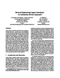
The CAMELEON Reference Framework is an approach that defines several levels of abstractions for specifying user interfaces. This framework can be aligned with the Horseshoe Model, which is a conceptual model for software reengineering. In Figure 1, we show the Horseshoe model tailored for UI reengineering.
Finally, the Horseshoe Model advocates for a forward engineering approach where the generation of the low level artefacts is guided by the higher-level models. In the case of the CAMELEON framework, the Task Model, the Domain Model, and the AUI can be used to generate (semiautomatically) the CUI and the final UI. Although not all the UIDLs conform to the CAMELEON framework, we will build our reverse engineering tool upon this framework since it is suitable for reengineering as it is based on similar principles as the Horseshoe Model. MODEL-BASED REVERSE ENGINEERING APPROACH
In this section we will detail the reverse engineering phase (UI recovery) of the architecture shown above, discussing which additional models are need to generate the models proposed by the CAMELEON framework for representing UI at different abstraction levels. The type of legacy UIs that we want to encompass with our approach are: •
Textual User Interface (TUI). TUIs only use text, symbols and colors available on a typical text terminal, while Graphical User Interfaces (GUIs) typically use high-resolution raster graphics.
•
Rapid Application Environment (RAD). Oracle Forms and Borland Delphi are two examples of these kind of environments. They became popular in the 90’s by allowing developers to create management applications quickly by means of visual facilities. They reduce the development time by facilitating GUI design and coupling data access to GUI controls.
•
Primitive web applications. These are web 1.0 applications that were developed using HTML for the presentation layer, and events were handled in the server side (Javascript was not widely used yet). CSS was not widely used to layout web controls but this was frequently done with tables. They are featured by a poor user experience since neither Ajax nor embedded objects (like Adobe Flash players) were used.
Figure 1: Horseshoe model for UI reengineering
The approach consists of three main phases, which are depicted with arrows. The first phase is the reverse engineering of the legacy system that starts with the analysis of the legacy artefacts. This step can entail dealing with different kinds of artefacts. For instance, the UI can be defined in a programming language, XML or a proprietary format (text or binary), whereas event handlers are commonly expressed in some imperative language. From the legacy artefacts, a Concrete User Interface Model is obtained, which defines the UI in a platform-independent way. An Abstract User Interface Model is obtained by raising the abstraction level of the CUI so it is modalityindependent. The CAMELEON goes beyond and proposes the extraction of the Task and Domain Models that capture the intention of the original UI design. Note that the Task and Domain Models can be considered as Computingindependent Models (CIM) of the MDA approach [6]. As a result of the reverse engineering (recovery) phase, we will obtain information of different aspects that were not explicit in the original artefacts. This information can be expressed in the form of models of some UIDL. However, as we will explain, for being effective for this task UIDLs require some features which they typically not provide. The second phase involves performing structural and or behavioural changes in the original system in order to move it to a different platform or technology. The restructuring is applied on the UIDL that captures the source system.
The architecture we have devised is shown in Figure 2. Arrows represent model-to-model transformations, but the arrows that are originated in the Legacy Code which are injectors. An injector bridges two technical spaces [7], that is, it transforms artefacts in a specific formalism into a different one. For instance, code conforming to a grammar (grammarware) injected to some modeling framework (modelware) such as EMF/Ecore. Model-to-model transformations allow us to automate the conversion of models at different levels of abstraction. Cross-references from a model to the models that originated it have been omited for clarity. These cross-references between models allow us keep relationships between the different recovered aspects, as well as maintaining the traceability from the source artefacts. Legacy code represents the collection of artefacts that makes up the system (programming language files, configuration files, UI files, and so forth).
a well-known format such as XML. In other cases, a dedicated parser could be used. AST models are dependent on the language in which the code is expressed and it is possible to abstract these models to obtain language-independent models. This has the advantage that later reverse engineering algorithms can be reused for different languages. In this sense, Knowledge Discovery Metamodel (KDM) [10] could be used to represent language-independent code. Source UI Model
Figure 2: Reverse engineering approach proposed
In general obtaining a high-level representation of a system requires going through several abstraction levels and transformation steps, and in the case of the UI the CAMELEON Reference conceptually provides such levels. However, in our experience dealing with reverse engineering we have found out that a simple transformation chain is not enough, but support models are needed to gather and reorganize the information, so that the transformation chain is complemented with these models. For example, in Figure 2 a Navigation model contributes the transformation to obtain the CUI and the Task Model. Low-level support models
Next we explain some of the support models we have identified so far, and later we discuss how they are used to obtain models from the CAMELEON Model. AST Model
An Abstract Syntax Tree (AST) model conforms to a metamodel which represents the abstract syntax of the underlying language. If the definition of the interface is mixed with the event handling (and in some cases also mixed with business logic or persistence) in programming language code, the AST model will represent all the code. This is the case when reverse engineering TUIs. Conversely, if the definition of the interface and the rest of the code are placed in separate modules (or at least in separated sections of the same module), the AST should just represent the code of the event handlers. AST models are obtained in different manners, depending on the nature of the source files. If the source code can be expressed with a grammar, then Gra2MoL [8] can be used to extract the models. When the source code is XML, there exist facilities to get models, such as the utilities of the Eclipse Modelling Framework (EMF) [9]. Sometimes the source code is stores in a binary proprietary format, so in this case company utilities are needed to convert the code to
This is a model which mirrors the user interface of the source system. A metamodel to represent such a system must be built. When the user interface is stored in a separate definition (e.g., an XML file), the model is generated directly from the definition. When the user interface definition is mixed with other code, as in TUIs, this model is obtained from the AST model. Layout Model
Legacy systems commonly have an implicit layout, i.e., the widgets are located in the window by means of absolute or relative coordinates. Expressing the layout in that way is not a good practice since if the size of the window is changed, its content is not resized accordingly. This is the case of some RAD applications and some hard-coded interfaces. Explicit extraction of the implicit layout is not a trivial task. In [11] this problem is addressed. When using a markup language for defining the user interface, e.g. HTML, the parts of the window are defined with marks. In many cases, tables were used to layout old web pages, and this is a discouraged practice by the W3C, so extracting an explicit high-level layout from web pages is also interesting. Due to parts of the window are limited with marks, the layout discovery is easier than the previous case. Some works like [12] [13] deal with the layout extraction from web pages. Navigation Model
This model represents the navigation relationships between the windows of the applications. They are frequently represented by means of Finite State Machines (FSMs). Some works [14] deal with the extraction of navigation flow from code models (AST, KDM, and others). In [15] authors perform static analysis on a text-based UI and obtain a transition graph which is represented with AUIDL. Data Model
A variety of data models are used in legacy systems, and for each kind a metamodel must be built. For instance, a metamodel for the SQL DDL could be used to represent a logical data model. It could be refined to obtain an entityrelationship model. Other Models
Some other information can be discovered from the UI definition model and the AST model. For example, a model that represents the validators that can be extracted for certain widgets, or the interactions among widgets. Another
example, could be a model representing dependencies among widgets. All this information will ease later restructuring and forward engineering phases. CAMELEON Models
Given that support models have been obtained CUI, AUI and Task models are derived by means of model transformations. CUI Model
The Concrete User Interface (CUI) Model will contain the information extracted from the different aspects of the source interface (e.g. layout, event handling or navigation) in a platform-independent way. This is not a complex task since this model is constructed by querying and information gathered in the previously obtained models. As an example, in [16] authors obtain a CUI from web pages. AUI Model
It is a modality-independent representation of the CUI. This is a relatively straightforward transformation since is based on abstracting the concepts that appear in the CUI model. In [17] some examples to obtain AUI elements from CUI are explained for the UsiXML language. Task Model
Obtaining high-level tasks from a source system is not a trivial issue. Task models cannot be derived just with the information contained in the AUI model, but additional information is required. There are works like [18] in which static program analysis techniques such as control flow analysis, data flow analysis, or pattern matching are performed in order to extract the user interactions. Also dynamic analysis is performed to get the user interactions, such as in [19], which propose analysing the user traces to get the tasks. This problem is tightly-related with the problem of obtaining business process models (BPMN) from low-level artefacts. In [20], the authors address the problem of obtaining BPMN models from KDM models based on pattern recognition. We believe that the construction of the Task Model can be facilitated by some of the models that we have previously obtained. For example, the Navigation Model captures the windows that can be reached from a certain window. If we assume that different windows are used to achieve different goals, we can use heuristics over the Navigation Model to know which tasks are derived from other tasks. Other additional models can also be useful. For example, if we have an Interaction Model that captures the dependencies among widgets, it is possible to know which widgets are affected by others. Then we could think of a heuristic that groups those widgets that are related and associate them with the same task. Domain Model
In many cases is represented with a UML class model although the source system does not need to be objectoriented. Most legacy systems store application data in a
relational database. If the database schema is available, Domain Model can be easily obtained. In this information is not available, we can analyse the Source UI Model and or the AST to see what information is displayed in the screen. Even if the database schema can be used, this can include much more information than the information involved in the application, so using the UI Model could enhance the Domain Model. The information contained in the Layout Model can be useful as a hint to know about close fields in the window, which are likely to be conceptually-related. APPLICATION SCENARIO: RAD APPLICATIONS
As explained in the introduction, we are developing a reverse engineering tool in the context of RAD applications, where GUIs are an essential element. RAD-based applications have some specific constraints that affect the UI recovery. We particularly highlight two features. First, the layout is not explicitly defined by using high-level layouts (e.g., Flow Layout in Java Swing), but it is implicitly defined by the position of the elements, which are expressed in terms of relative or absolute coordinates. Keeping this type of layout is not a good practice, because this means that, for example, when a window is resized the widgets are not resized or rearranged accordingly. The second feature is that code managing the GUI is mixed with business logic and database access, i.e., there is no clear separation among the different concerns of the application. This entails that extracting information of a certain aspect requires analysing all the code. In Figure 3 we show the model architecture we have implemented. Solid lines are injectors and model-to-model (M2M) transformations. Dotted lines are cross-references among models.
Figure 3: Architecture proposed for reverse engineering RADbased applications
At present we have just reach the CUI level, which is composed of: The Presentation Model, the RAD Behaviour Model, the Event Concerns Model and the Interactions Model. The architecture is exemplified with Oracle Forms as the source technology, but it could be used with any other RAD technology such as Borland Delphi or Microsoft
Visual Basic. The different models involved are described next, exemplified for Oracle Forms. All the model transformations have been implemented in RubyTL [21].
since it eases static analysis of a RAD system. Particularly, it let us get the Event Concerns Model and the Interactions Model [22].
Source Artefacts
To adapt this architecture to a different legacy technology, this model should be replaced for a domain-specific behaviour model if it is possible to identify commonalities in the event handler code of a domain, or it can be supressed and all the static anaylisis would be based on the AST Model.
The source artefacts in the case of Oracle Forms are XML files that include the definition of the different windows of the application. These files also include some other information, e.g. information about database tables linked to widgets. The presentation elements such as widgets or windows can have some event handlers associated with them, which are expressed in the form of PL/SQL triggers. The PL/SQL code is embedded in the XML files.
Event Concerns Model
From the XML files, two models are obtained. The Source UI Model is obtained by means of a EMF tool for injecting models from XML code, and the AST model (PL/SQL models in our case) which is obtained with Gra2MoL, which allow us to get models from code that conforms to a grammar.
Legacy systems often mix UI code with business logic or control code in event handlers. This support model is aimed at identify fragments of code which are related to the same concern so that it is possible to achieve separation of concerns. It helps us to the understand event handlers, and it can be useful when restructuring the source system in order to create a new one with better quality in terms of extension and maintenability.
Source UI Model
Interaction Model
It is a model that represents the source GUI. Although it is not explicitly depicted in Figure 3, two different models are involved. Firstly, a model that mirrors the original Forms GUI is obtained. From this model, a model-to-model transformation gets a second model, called RAD Model, that represents the source system in terms of common concepts provided by RAD environments. This is a kind of normalization model for GUIs built with a RAD, in order to make the rest of the process independent of the specific RAD environment.
The goal of this model is twofold. On the one hand it represents the navigation flow by means of a state machine. On the other hand, it explicitly show the dependencies that exists among the GUI elements. For example, provided there is a checkbox that enables a panel when it is checked, this model will capture the interaction that exists between the checkbox and the panel.
Low-Level Layout Models
As said, in desktop legacy applications (such as applications created with RAD) the layout is implicitly defined by the position of the elements, which are expressed in terms of coordinates. This means that, for example, when a window is resized the widgets are not resized or rearranged accordingly. We have defined a couple of low-level layout models to support the discovery of an explicit layout model. Although they are auxiliary models, they are useful to bridge the gap between the original layout based on coordinates and the CUI model. More details about these models and the algorithms involved are given in [11]. Presentation Model
This model defines the structure of the GUI (i.e., which views compose the GUI and which are the containment relationships among the graphical elements of the views), as well as the layout (i.e., how the graphical elements are arranged in the views). RAD Behaviour Model
This model captures the behaviour of the source code in terms of simple primitives which are common in RAD environments, such as read data from a database or write some data in the GUI controls. This model is the basis on which we extract more knowledge about the source code
Putting the pieces together: CUI Model
In summary, our CUI model represents GUIs developed with RAD environments, and it is specifically tailored for the reverse engineering of these kind of applications. The models that compose the CUI level are: •
The Presentation Model which defines the elements in the GUI and their layout.
•
The RAD Behaviour Model which defines the behavioural part of the GUI (the event model).
•
The Interactions Model which defines navigation relationships and dependencies among widgets.
•
The Event Concerns Model that enriches the RAD Behaviour Model by specifying categories of code in the event handlers.
We aim at generalising the CUI to deal with other legacy scenarios, as the ones presented before (TUI and web applications). CONCLUSIONS AND FUTURE WORK
In this paper we have presented a model-based architecture to perform reverse engineering of legacy UIs based on the CAMELEON framework. We have shown the concrete model arquitecture we have built to reverse engineering RAD-based applications. As a future work, we will continue with the development of the reverse engineering tool in order to reach all the abstraction levels defined in the CAMELEON framework.
In addition, the architecture will be extended to consider Textual User Interfaces and legacy web applications. ACKNOWLEDGMENTS
This work is partially supported by Consejería de Universidades, Empresa e Investigación (grant 129/2009) and Fundación Séneca (project 15389/PI/10). REFERENCES
12. Bandelloni, R., Mori, G. and Paternò, F. Dynamic Generation of Web Migratory Interfaces. Proceedings of the MobileHCI’05. 83-90. 13. Cai, D., Yu, S., Wen, J. and Ma, W. VIPS: a VisionBased Page Segmentation Algorithm. Microsoft Research TechReport. 2003. http://research.microsoft.com/apps/pubs/default.aspx?id =70027.
1. Selic, B. Personal reflections on automation, programming culture, and model-based software engineering. Automated Software Engineering, 15, 3-4 (December 2008), 379-391.
14. Staiger, S. Reverse Engineering of Graphical User Interfaces Using Static Analyses. Proceedings of the WCRE’07.
2. Myers, B., Hudson, S. and Pausch, R. Past, present, future of user interface tools. ACM Trans. Comput.Hum. Interact. 7, 1 (March 2000), 3-28.
15. Merlo, E., Gagné, P., Girard, J., Kontogiannis, K., Hendren, L., Panangaden, P., De Mori, R. Reengineering User Interfaces. IEEE Software, 12, 1 (January 1995), 64-73.
3. Calvary, G., Coutaz, J., Thevening, D., Limbourg, Q., Bouillon, L., and Vanderdonckt, J. A Unifying Reference Framework for Multi-Target User Interfaces. Interacting with Comp. 15, 3 (June 2003), 289-308. 4. James, M., Rapid Application Development. Macmillan Publishing Co., Inc. 1991. 5. Kazman, R., Woods, S. G. and Carrière S. J., Requirements for Integrating Software Architecture and Reengineering Models: CORUM II. Proceedings of the WCRE’98, 154-163. 6. OMG Model Driven http://www.omg.org/mda/.
Architecture.
7. Bézivin, J. and Kurtev, I. Model-based Technology Integration with the Technical Space Concept. Proceedings of the Metainformatics Symposium. 2005. 8. Cánovas Izquierdo, J. L. and García Molina, J. A Domain Specific Language for Extracting Models in Software Modernization. Proceedings of the ECMDAFA ’09, 82-97. 9. Eclipse Modeling Framework Project http://www.eclipse.org/modeling/emf.
(EMF).
10. OMG Knowledge Discovery Meta-Model (KDM) v1.0. 2008. http://www.omg.org/spec/KDM/1.0/. 11. Sánchez Ramón, O., Sánchez Cuadrado, J. and García Molina, J. Model-Driven Reverse Engineering of Legacy Graphical User Interfaces. Proceedings of the ASE’10. 147-150.
16. Vanderdonckt, J and Bouillon, L and Souchon N. Flexible Reverse Engineering of Web Pages with VAQUISTA. Proceedings of the WCRE'01. 17. Limbourg, Q., Vanderdonckt, J. Multipath Transformational Development of User Interfaces with Graph Transformations. Human-Centered Software Engineering: Software Architectures and Model-Driven Integration, Chapter 8, Vol. II, Springer HCI Series, Springer-Verlag. 2007. 18. Paganelli, L. And Paternò, F. Automatic Reconstruction of the Underlying Interaction Design of Web Applications. Proceedings of the SEKE’02. 439-445. 19. El-Ramly, M., Iglinski, P., Stroulia, E., Sorenson, P and Matichuk, B. Modeling the System-User Dialog Using Interaction Traces. Proceedings of the WCRE’01. 20. Zou, Y., Lau, T., Kontogiannis, K., Tong, T. and McKegney, R. Model-Driven Business Process Recovery. Proceedings of the WCRE’04. 21. Sánchez Cuadrado, J. and García Molina, J. Modularization of model transformations through a phasing mechanism. Software and System Modeling, 8, 3 (July 2009), 325-345. 22. Sánchez Ramón, O., Sánchez Cuadrado, J. and García Molina, J. Reverse Engineering of Event Handlers of RAD-Based Applications. Proceedings of the WCRE'11 (acceptance pending).