In Ethernet, a frame has a minimum length of 84 bytes (including the Inter-Packet. Gap of 12 bytes). Observing an example of a station that needs to (cyclic) send.
Augmenting Networked Control Systems in the realm of Industry 4.0 Master Thesis Arno Schmetz
This work was submitted to the Chair of Communication and Distributed Systems RWTH Aachen University, Germany
Advisers: M.Sc. Jan R¨uth M.Sc. Ren´e Glebke Examiners: Prof. Dr.-Ing. Klaus Wehrle Prof. Dr.-Ing. Stefan Kowalewski
Registration date: 2016-05-25 Submission date: 2016-11-25
Eidesstattliche Versicherung
Schmetz, Arno ___________________________ Name, Vorname
292737 ___________________________ Matrikelnummer (freiwillige Angabe)
Ich versichere hiermit an Eides Statt, dass ich die vorliegende Arbeit/Bachelorarbeit/ Masterarbeit* mit dem Titel
Augmenting Networked Control Systems in the realm of Industry 4.0 __________________________________________________________________________ __________________________________________________________________________ __________________________________________________________________________ selbständig und ohne unzulässige fremde Hilfe erbracht habe. Ich habe keine anderen als die angegebenen Quellen und Hilfsmittel benutzt. Für den Fall, dass die Arbeit zusätzlich auf einem Datenträger eingereicht wird, erkläre ich, dass die schriftliche und die elektronische Form vollständig übereinstimmen. Die Arbeit hat in gleicher oder ähnlicher Form noch keiner Prüfungsbehörde vorgelegen.
Aachen,25.11.2016 ___________________________
___________________________
Ort, Datum
Unterschrift *Nichtzutreffendes bitte streichen
Belehrung: § 156 StGB: Falsche Versicherung an Eides Statt Wer vor einer zur Abnahme einer Versicherung an Eides Statt zuständigen Behörde eine solche Versicherung falsch abgibt oder unter Berufung auf eine solche Versicherung falsch aussagt, wird mit Freiheitsstrafe bis zu drei Jahren oder mit Geldstrafe bestraft. § 161 StGB: Fahrlässiger Falscheid; fahrlässige falsche Versicherung an Eides Statt (1) Wenn eine der in den §§ 154 bis 156 bezeichneten Handlungen aus Fahrlässigkeit begangen worden ist, so tritt Freiheitsstrafe bis zu einem Jahr oder Geldstrafe ein. (2) Straflosigkeit tritt ein, wenn der Täter die falsche Angabe rechtzeitig berichtigt. Die Vorschriften des § 158 Abs. 2 und 3 gelten entsprechend.
Die vorstehende Belehrung habe ich zur Kenntnis genommen:
Aachen, 25.11.2016 ___________________________ Ort, Datum
___________________________ Unterschrift
Abstract
Currently, a set of systems for controlling actuators and sensors like in industrial facilities use networked control systems (NCS), sending data from devices to a networkconnected controller responding with control signals for sensors and actuators. The vision of control systems includes distant controllers like a Cloud providing more flexibility and possible combinations to other concepts. In this work, we tackle the problem of delays between sending data and receiving controlling instructions. By using simulation, we show the feasibility of an in-network control system design which significantly decreases the horizontal network delay caused by network transmissions. Our design enables simple network devices – like switches – to do simple tasks and computations defined by observing the packets in the network and alter them or generate control messages on their own while the original controller may refine the instructions later on following rules that can be programmed into these devices at runtime. The design introduces adds a small ruleset and execution engine to the Data Link Layer of the traditional ISO/OSI layer model while keeping legacy support. Additionally, building upon the WARP board architecture we show the applicability to real devices and aim for reducing the vertical“ network delay intro” duced by network stacks in modern computers. We show that there are controlling tasks that fail using a distant cloud-based controller while succeeding when using our approach including a scenario taken from a real-world production facility. For other tasks, we achieve a better performance when applying our concept to a small subset of controlling tasks. Further, we provide a short overview of future optimizations and extensions that can be applied to our system.
Acknowledgments First of all I want to thank Jan R¨ uth and Ren´e Glebke for supervising and supporting me during my work including many interesting discussions. Many thanks to Martin Serror who provided the WARP board for this thesis and gave a great introduction to it. Further, I want to thank the people of Fraunhofer Institute of Production Technology (IPT). We gained insight to industry and production processes. We were allowed to visit a new production system and use the insights for this thesis. Thanks espacially to Sebastian Haag who I had first and most contact with.
Contents
1 Introduction
1
2 Background
5
2.1
Basics of Control Theory . . . . . . . . . . . . . . . . . . . . . . . . .
5
2.2
Programmable Logic Controllers . . . . . . . . . . . . . . . . . . . . .
6
2.3
Network Stack . . . . . . . . . . . . . . . . . . . . . . . . . . . . . . .
7
2.4
Bus Systems . . . . . . . . . . . . . . . . . . . . . . . . . . . . . . . .
8
2.5
Industry 4.0 . . . . . . . . . . . . . . . . . . . . . . . . . . . . . . . .
9
2.6
Networked Control Systems . . . . . . . . . . . . . . . . . . . . . . . 10
2.7
Software-Defined Networking . . . . . . . . . . . . . . . . . . . . . . . 13
2.8
WARP Board and 802.11 Reference Design . . . . . . . . . . . . . . . 14
3 Related Work
17
3.1
OpenFlow . . . . . . . . . . . . . . . . . . . . . . . . . . . . . . . . . 17
3.2
Smart Packets . . . . . . . . . . . . . . . . . . . . . . . . . . . . . . . 19
3.3
Tiny Packet Programs . . . . . . . . . . . . . . . . . . . . . . . . . . 20
3.4
P4 . . . . . . . . . . . . . . . . . . . . . . . . . . . . . . . . . . . . . 21
3.5
EtherCAT . . . . . . . . . . . . . . . . . . . . . . . . . . . . . . . . . 24
3.6
SANTA . . . . . . . . . . . . . . . . . . . . . . . . . . . . . . . . . . 26
4 Design
27
4.1
Problem Statement . . . . . . . . . . . . . . . . . . . . . . . . . . . . 27
4.2
Basic Concept . . . . . . . . . . . . . . . . . . . . . . . . . . . . . . . 29
4.3
Data Structures . . . . . . . . . . . . . . . . . . . . . . . . . . . . . . 32
4.4
Reflex Execution Engine . . . . . . . . . . . . . . . . . . . . . . . . . 33
5 Measurements and Simulations
37
5.1
Vertical Delay Measurements . . . . . . . . . . . . . . . . . . . . . . 37
5.2
WARP Implementation . . . . . . . . . . . . . . . . . . . . . . . . . . 41
5.3
Simulations . . . . . . . . . . . . . . . . . . . . . . . . . . . . . . . . 45 5.3.1
UDP Traffic Test . . . . . . . . . . . . . . . . . . . . . . . . . 46
5.3.2
IPT Simulation . . . . . . . . . . . . . . . . . . . . . . . . . . 48
6 Conclusion
55
7 Future Work
61
Bibliography
65
1 Introduction Industrial facilities in manufacturing, aviation, military and others consist of multiple sensors and actuators that need controlling and observation. The history of control systems reaches back to 1868 when Maxwell conducted dynamics analyses of the centrifugal governor. [30] One major achievement later in history has been the fly-by-wire flight control system which removes the complex mechanical control system. One of the first (analog) fly-by-wire system was used in the Boeing B-17 autopilot C-1. [34] Digital computers and microprocessors advanced to a new magnitude of capabilities for control systems inspiring embedded controllers like in today’s cars. [26] In the past decades, production phases were split into rather isolated systems specialized to one task. In current research, the idea of connecting these phases is presented. Further, the vision of using a distant controller like a cloud service, smart facilities and integration of new technologies is a major subject in research. This vision is often referred to using the term Industry 4.0. [28] This vision allows a more flexible way of producing goods and the integration of new concepts like Big Data into the production and management process. [29] For example, a company is producing mugs for customers using traditional systems. Every change of the product design needs adaptions of the devices and controllers in the facility which may cost time and money and possibly include replacements of controllers or introduce side-effects. To gain insight about the design change that is fitting best the customer’s wishes, studies have to be made introducing additional costs. In a possible scenario, a cloud system controls the whole production process while a Big Data service observes sources like market reviews and social media concerning the product and extract connections like breaking mugs in certain environments or customers wanting a better handle. The cloud can present such information to the management of the company which decides to use the new design. Using flexible devices in the facility, the controller can change the instructions sent to the devices in the production facility and by this change the product. This example is a possibility introduced in the vision of Industry 4.0 and further ideas but
2
1. Introduction
it also introduces a set of challenges. One major problem using a distant controller is the introduction of network delay. For transmission of data from one device in the facility to the controller, the network causes a significant delay which slows down the production or even results in production steps becoming impossible. Industry 4.0 describes a current development but the idea of more flexible facilites and cloud integration to the production process goes further. The vision also allows a more advanced control for tasks beside the industry. Control is also needed for the interconnected home to sense and react upon events happening at home. The same holds for a city which collects data of traffic, people and the environment to use instruments aiming for a better life in this city. There are many applications of interconnected systems with control to achieve a goal. Using local controllers lacks in flexibility where a distant flexible controller like a cloud service has significant advantages. The delay between an event happening or a sensor sensing data and the corresponding data being processed and acted upon can have a severe impact on the whole production or control process. While some actions can be paused or split up into parts allowing pauses between operations to waiting for instructions from a controller, other processing steps cannot be paused or have to be executed in a time-critical way (e.g., the transport of melted metal to its destination before it cools down). In an interconnected environment, there is a significant delay introduced by the network that is used for communication resulting in this delay problem. Using a distant controller like a Cloud service, the delay introduced by communicating with the controller is significantly greater than using a local controller and is harder to estimate. This is the main problem we are tackling in this thesis. To tackle the delay problem, we examine the possibility of augmenting network devices for controlling purposes. We describe a concept of adding small rules to the devices that are executed during runtime. Using the rules, the devices can react on messages from facility devices earlier than a distant controller due to the communication delay. We design these concept to recognize, relay, change and generate frames depending on the rules that are applied. Further, the adapted device use a reflex execution engine which also allow checking conditions and simple tasks like conversions of the payload. This concept allows the transfer of a subset of the control needed for the facility to the network itself. Currently the major research and development target the concept of Industry 4.0 in which our system can be applied and used but our concept is not limited solely to the context of Industry 4.0 but also general interconnected systems and others. In this thesis we only focus on production systems to show the feasability of this approach. In detail, we use simulations to show the impact of delay in production scenarios and the response of these scenarios when adding our system. Intuitively, this concept is similar to reflexes in the human body. Therefore, we call this Reflexes. Structure of the Thesis In the next chapter, we provide some background on control systems, the network stack and programmable logic controllers as well as a short introduction to industry
3 4.0. In the related work chapter, we show the adaption of control systems – namely networked control systems – and concepts of reducing the impact of network delay in control systems using different ideas like EtherCAT, OpenFlow and SANTA as well as their drawbacks. In chapter four the delay problem in industrial networks is analyzed and the Reflexes system is defined. The next chapter contains the results of the measurements and the simulations and describes them. Further, the Measurement and Simulation Setups are shown as well as information on the implementation of the concept using WarpBoards. Chapter 6 provides a discussion of the results and evaluate the designed concept. The last chapter provides a short overview of possible future work regarding our concept and the results.
4
1. Introduction
2 Background In this chapter, we describe the basic concepts of control systems that we use and adapt in this thesis. For intuitive understanding, two simple examples are used. The first example is an autopilot for a plane. The autopilot’s task is to steer the plane directly to the destination. The plane has mechanical wings enabling steering operations as well as a compass and GPS for sensing position and orientation. Another example describes a small robot with two motors attached to its to wheels enabling the wheels to be rotated in both directions. The task is to complete laps defined by a black line on the white ground while using only a small camera in front which is able to detect whether the area directly in front of the robot is the black line or white background.
2.1
Basics of Control Theory
Control systems are systems designed to regulate inputs to devices like facility actuators following a model in a looped fashion. An example is the autopilot for planes which adjusts the wings to keep the plane in line to the destination, using sensor information like a compass to determine the adjustments. Figure 2.1 describes a basic control system using feedback of the plant, creating a single loop of control. The plant is affected by external factors and disturbances (d) and provides outputs and signals given by y. These outputs are measured by the sensor which is also affected by noise (n). The controller uses the sensor information (v) as well as a reference signal or command input (r) to determine the input for the plant such as signals and commands (u). The controller is performing this every time it gets data from the sensor which makes the system a control loop. For a complex facility multiple (possibly isolated) control loops are used (e.g. one per production step). [16] The domain of control and signals can be the frequency or the state domain. In the plane scenario, we observe the current course and position using a compass
6
2. Background
d r
u plant
controller
y
v sensor n Figure 2.1 A general Control System as described in [16].
and the GPS system. The plant (the plane) provides output given by the position and course at the moment. The sensors (GPS and compass) evaluate and measure these outputs and present the results to the controller. This controller computes the correction of course needed for targeting the destination exactly and feed the plant with instructions. Such a system is called stable if certain criteria are matched. Intuitively this stability is achieved if small perturbations from the optimal signal (the perfect course in the plane scenario) – also called equilibrium state – do not result in high perturbations after multiple control loops. Another domain of control and signals is defined by a state-space concept. In the robot example, the plant (the robot) changes its position and orientation. The sensor is able to detect whether the small floor area in front of the robot is white or black. The controller gets such a state information and is able to interpret the result as being on the path or not on the path at the moment. Depending on this information the controller sends a state change command to the motors (e.g., rotate forward). The system stability evaluation needs to be defined with respect to the task. The optimal signal can be achieved by stopping the movement after the moment the black line has been detected but this will not result in completing laps. [36] The detailed definition of the mathematical models is omitted in this section because significant parts are shown in section 2.6 and other parts of control theory will not be the focus of this thesis.
2.2
Programmable Logic Controllers
Programmable Logic Controllers (PLCs) [25] are widely used devices for adding control to a production facility. They consist of (program) memory, CPU and interfaces and work in the cyclic scanning mode. This mode can be seen abstractly in figure 2.2. Every cycle starts with reading current inputs and then execute the program the PLC contains. At the end, the program writes the outputs to the output interfaces and the PLC performs internal checks before starting the next cycle. By that,
2.3. Network Stack
7
r ead I nput s i nt er nal c hec ks wr i t e Out put s
pr ogr am ex ec ut i on
Figure 2.2 Cyclic Scanning Mode – After reading input values, the PLC executes the program and writes output values. After internal checks the cycle starts over again.
the PLC will react on specific inputs after up to 2 cycles, which can be a relatively long time in case of large programs to execute, but also provide a fixed upper bound for the reaction time. Therefore a programmer needs to evaluate the time that is needed for executing a program in the cycle and examine the feasibility in terms of time needed for a response. In the plane scenario, the sensors compute orientation and position all the time and write the results to the PLC input. The PLC takes the latest inputs and computes the corrections needed for the target course. If the cycle lasts for a long time, the system might not be stable. A small deviation from target course can result in the command of steering which overshoots the target course leading to a course of more deviation in the other orientation than before. A possible solution for the robot scenario task is to aim for fast switches of white and black sensor information by which the robot will drive along the edge of the black line. Using cyclic scanning mode the controller can not react directly to a state change indicated by the camera but needs to wait for the next cycle input. In case of long execution times this can lead to huge turns instead of small ones and in worst case, these turns occurring in areas of curves of the black line the robot might turn around and never finishes the lap. It is possible to add simple network abilities for communicating with other PLCs and client, which is mainly maintenance. Currently, many PLCs are also reachable via the internet making it a threat vector as well. [21]
2.3
Network Stack
The OSI model describes an abstract layered concept for network communication. Those layers handle certain tasks like physical transmission, access control and routing. Regarding this model and the specific protocols of those layers operating systems like Linux provide a network stack implementation to enable applications to communicate with other systems and the Internet. Figure 2.3 shows the abstract Linux network stack. To send data to the network, the application creates the payload and triggers a context switch from user space to
8
2. Background
Application Userspace Kernel
TRANS NET Kernel Hardware
MAC Figure 2.3 Abstraction of the network stack in Linux/Unix. Receiving and sending data needs to traverse the kernel stack starting from hardware resulting in a user space application and vice versa. Those context switches introduce a significant delay. The figures is adapted from [37].
kernel space. In the kernel space headers (e.g. UDP, IP) are added, fragmentation may be applied and a network interface is chosen. After finishing work in the kernel, the buffer with headers and payload is copied to the hardware and will eventually be transmitted. For receiving data, the process takes place vice versa. The data has to be copied multiple times. One copy operation takes place when copying the data between the hardware interface and the systems kernel memory. A second copy operation takes place when copying the data between protected kernel memory and another area in the main memory allowing access to the data for applications not executed in the kernel space. [19] This network stack introduces delay between the application triggering and the network interface transmitting. This delay is caused by multiple factors. Most significant are the context switches between user space and kernel space in the operating system, the memory buffer copy operations and scheduling in the multi-tasking system. [24]
2.4
Bus Systems
To connect actuators, sensors and controllers special bus systems are used in most production facilities as well as automotive systems. A simple system is the InterIntegrated Circuit Bus (I2 C) [10] which allows short busses with multiple masters and slaves. The devices get attached a unique address of 7 bits which also denotes the priority for the device. The bus uses two lines where one line is used for synchronization while the other is used for data transfer. The wires use a wired-and meaning that if two devices try to send simultaneously different values, the result is always the 0 bit. The master sends data starting with the address of the target
2.5. Industry 4.0
9
device including a bit indicating whether this device has to read or write data. The devices read the data and set an acknowledged flag on the data line after the data or write directly to the line. The master can read the data directly by sensing the data line. No device can send data to the master on its own but needs to wait for the next cycle its address is planned in causing delay. One major drawback is the use of fixed addresses also being the priority of the device in the system. In a scenario of changing production steps, these priorities might change. Further, this addressing also limits the number of devices to a small number. Another popular bus system is the Controller Area Network Bus (CAN – or CANopen in industrial fields). [39] As I2 C it uses the wired-and wiring and limits the number of devices to 32 (up to 128 with additional limitations). To overcome the problem of device number limitation and cable limits, the system allows the use of repeaters and bridges. Instead of focusing on devices and addressing them, CAN uses unique identifiers for messages. These messages can be sent by devices and multiple other devices can listen for the messages (e.g., two winkers to activate on one signal generated in reaction to the user action). Priority is given to the messages depending on the identifier. For industrial systems, a small set of profiles of applications and devices is specified and CANopen provides application layer CAN is hardly applicable to a flexible environment because the identifiers for the messages are defined in the specification making adaptions and introduction of new message types quite inflexible. Process Field Bus (PROFIBUS) [11] is a bus system designed for automotive and industrial automation and was a publicly founded german research project. It follows the master/slave concept and the master polls the slaves in cycles. If a slave wants to send data to another slave it has to wait for the cycle it gets addressed by the master and then send the data to the master which sends the data to the destination device later. By adding more devices to PROFIBUS, the effective data rate possible for each device is reduced for every new device. The number of devices used in a PROFIBUS system is limited to 32 but it can be extended using repeaters up to 128 devices. Additionally, the system has multiple operation modes including a mode with reduced voltage for industrial facilities with explosion hazard. The maximum cable length is given with 1,200 m also limiting the data rate further. More traditional bus systems are existing but they also introduce the problems and limitations we described in example for three of the most popular systems above.
2.5
Industry 4.0
Producing material goods is part of our economy for long time. Bringing optimization and automatization to the production process defines the modern industry. During history research and development lead to major changes in the industry – so-called industrial revolutions. The first industrial revolution was marked by the introduction of production facilities using steam power. The next revolution has been possible by electrical energy coming with the division of labor and mass production. The last revolution describes the use of electronics in the production automation. Currently, the next revolution is
10
2. Background y
w Communication Channel (Delay & Data loss)
P
plant
P
controller
u
v
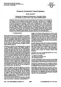
Figure 2.4 A general Networked Control System according to [40]. The sensor outputs (y) are sent through the P communcation channel. The delayed sensor information (w) are inputs for the controller ( controller ), which sends outputs (v) through the communation channel. P The delayed controller output (u) is the input for the actuators in the plant subsystem ( plant ).
considered to take place and is called industry 4.0. The vision of this includes the use of new technologies like Big Data [29] for industry as well as interconnected systems and more flexible facilities. In contrast to the last revolution the electronic systems are not designed to operate isolated from each other but using interconnections and act more intelligent on their own. This need for flexibility makes specialized devices less feasible than general purpose hardware. Unlike traditional production systems with fixed devices and controllers, flexible and powerful controllers are used, possibly a Cloud. Such a Cloud may enable the users to collect data of the process, analyze it using mechanisms of Big Data and remotely change production procedures. [28] A potential problem of a production can be the delay of the controller reacting to events in the facility when being placed in a distant Cloud. This delay of the network connecting facilities and Cloud is the problem we are tackling in this theses but also other researchers have presented ideas for dealing with the delay which are presented in the next chapter including their drawbacks.
2.6
Networked Control Systems
Networked Control Systems (NCS) are control systems that are connected via a communication channel shared with other network devices. Using this channel, information (reference input, control input, etc.) is exchanged with other devices in the NCS (sensors, actuators, etc.). We P can formulate a NCS as a linear system. We define the first subsystem S1 using plant = (A, B, C, D) as continous with state variable x, output vector y and input vector u. By that we can define
x(t) ˙ = Ax(t) + Bu(t) y(t) = Cx(t) + Du(t) The second subsystem – the controller – given by discrete-time system with the state z, such that
zk+1 = Ezk + F wk vk = Gzk + Hwk
P
(2.1) (2.2) controller
= (E, F, G, H), is a
(2.3) (2.4)
2.6. Networked Control Systems
11
where wk is the input to the controller, given by wk = w(kT ) describing the delayed version of the sensor output y(t) at some sampling instant of sampling period T . Concerning element i in wk , namely wki we can define
i wki = y i (t − τsc (t))
(2.5)
i is the time delay between sensor and controller concerning the ith sensor where τsc i signal y (t), for which holds
i 0 < τsc (t) ≤ τscmax ∀i
(2.6)
i (t), that can be greater than T . Analog to the where τscmax is the upper bound for τsc sensor outputs, output vk and actuators is given P the time delay between controller j by u(t) in plant . The delay is described by τca (t) with bounds
j 0 < τca (t) ≤ τcamax ∀j
(2.7)
where the upper bound τcamax can also be greater than the sampling period T . Figure 2.4 shows this networked control system including a communication channel, where delay and data loss can be induced. The described controller is time-driven. It uses a sampling period of T meaning that every point k in time, kT , the controller starts its calculation. The sensors in the plant have their own sampling periods for calculating and sending their information. This concept is very simlar to the scanning cycles described in section 2.2 The sampling period for sensor i is given by
T pi = βi T, β ∈ R>0
(2.8)
for N sensors and 1 ≤ i ≤ N . A possible simplification is setting all β to 1, resulting in the same sampling periods for sensors and controller. In case βi is an integer, the clocks of sensors and controller are not synchronized, instead there is a fixed time skew γi between the clocks of sensor i and the controller. This can be seen in figure 2.5. The skew γi is fixed between the clocks of the controller and the sensor i which has βi = 1. βi+1 in the figure has a non-integer value which leads to no fixed time skew over time. i Every sensor sample is indexed by yli , yl−1 , · · ·, where yli is the current sample and i yl−1 the sample sampled one period before. The controller uses the sample with the largest l, meaning the most recent sample. Because of (2.6) and the possibility of packet loss it is possible that
i i wk+1 = wki = yli (t − τsc (t))
(2.9)
12
2. Background clock of sensor i + 1
clock of sensor i time skew γi clock of controller kT
(k + 1)T
(k + 2)T
(k + 3)T
(k + 4)T
(k + 5)T
Figure 2.5 The ith sensor clock has a sampling time skew regarding the controller while the clock of sensor i + 1 has a sampling time coefficient βi+1 ∈ / N. In consequence, the clocks of the controller and sensor i have a fixed skew, while the time skew of controller and sensor i + 1 is varying. (figure is adapted from [40].)
meaning that after a sampling period the controller did not get any new samples. The actuators in this model work event-driven, meaning they calculate and actuate immediately after receiving a signal. Because of (2.7) and the possibility of packet loss, the time of the value stored in the actuator can be longer than T which in the worst case results in severe production problems (e.g., moving an arm too far). Using these sampling periods, the system has a determinism similar to the traditional control systems but also the problem of unpredictable network delay and packet loss rates reducing the determinism. [40] Currently, NCSs are subject of active research. Main topics of research are approaches of delay reduction and estimation as well as fault tolerant controllers tackling problems of packet losses. Another approach is to remove the sampling periods and replace them with event-based controls to achieve a more flexible but less deterministic system. By that, the controller can react faster to messages from the plant potentially increasing the overall performance. When having a sensor with a high update frequency this may also result in much overhead. Instead of computing the reaction based on the latest measurements, the computation takes place for every single measurement. Further, in a network populated with several sensors frequently sending updated values triggering reactions of the controller, the network load may increase in total because more messages need to be scheduled and transmitted in the network. This is hard to estimate and has a negative influence on guarantees of the communication channel even and even has a chance of failing due to an overloaded network. [27] In this thesis we will use devices with sampling periods as well as event-based concepts. Thinking of the examples of the plane and robot again we can simply transform the PLC design to a networked control system for these. The cyclic scanning approach can be transformed to the sampling periods of the Networked Control System. While
2.7. Software-Defined Networking
13
Network Applica�on(s) Open northbound API
Controller Pla�orm Open southbound API
ts en s) m e l he g e witc n i s rd wa Flow r o n f pe ta Da g., O (e.
Network Infrastructure Figure 2.6 The basic structure of the SDN architecture. (The figure is taken from [23])
in the PLC example, the main problem was introduced by the program execution time in the PLC we can use high-performance controllers or even a Cloud in the NCS. By moving the controller to a distant location we introduce a bigger communication channel resulting in more dominant network delays.
2.7
Software-Defined Networking
Network operators create high-level network policies and want to add them to the network. To do this, they need to transform their high-level policies into low-level commands and configure the network and its devices accordingly. This configuration is done differently depending on the device because vendors define the command set the operator has to use. Further, flexible or automatic reconfiguration during runtime is a virtually non-existing feature in traditional networks. Especially, the control plane deciding how traffic needs to be handled and the data plane which is forwarding traffic based on the decisions of the control plane are bundled in traditional network devices making them even more static and inflexible. The paradigm of Software-Defined Networking (SDN) [23] tackles this problem. The main idea is the separation of the control and data plane in the devices. The data plane stays in network devices like switches while the control plane is outsourced to a logically central controller. This central controller needs not to be a physically centralized system. Figure 2.6 shows the basic structure of the SDN architecture. Network applications communication with the controller platform (control plane) and the controller platform interacts with the network devices that forward messages (data plane). Instead of deciding how to perform relaying based on the destination solely, the network devices have more complex instructions for this task. This results in a focus on flows instead of destinations in the network. In the past decades, a set of approaches for SDNs have been presented. The Open Signaling working group proposed open and programmable switches in 1995 which
14
2. Background
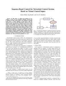
Figure 2.7 The architectural concept of the 802.11 reference design for WARP v3 borads. (Taken from [5])
resulted in an IETF working group. They designed a general purpose management protocol for switches which allowed configuration and resource management during runtime. They stopped working in 2002. In the 1990s the Active Networking initiative proposed the idea of networks that can be programmed regarding their infrastructure to provide better support for customized services. The concept included programmable switches as in other SDN architectures but also provided the base for executing code in the network devices. This resulted in other projects like Smart Packets (see Section 3.2). Active Networking never gathered a critical mass for widespread use in industry deployment. Another project was the 4D Project. In 2004, they added more planes to the management to provide a global view of the network for the decision plane. Their work ended but also inspired other projects like the NOX project. A slightly different approach was presented in NETCONF. The researchers designed an API for changing configuration at runtime of network devices. The problem was that changes needed to be added to the controller and the device reducing the flexibility and making the concept only an aid for automated configuration in practice. These notable projects and others inspired other researchers in the past decades. They also inspired the OpenFlow architecture which is very popular in academia as well as industry. [32]
2.8
WARP Board and 802.11 Reference Design
The Wireless Open-Access Research Platforn (WARP) [5] provides a hardware platform for research with capabilities for rapid prototyping of custom wireless designs and protocols. The WARP board version 3 we are using provides a Field Programmable Gate Array, memory and a set of interfaces. In our work we use only the 802.11 reference design (provided by Mango communications [3]) and change only the software but not the FPGA itself.
2.8. WARP Board and 802.11 Reference Design
15
The WARP board 802.11 reference design is divided into several layers. These layers are shown in Figure 2.7. The lowest layer is the hardware itself – the WARP board version 3 and the basic hardware support layer for controllers. The physical layer presents functions for receiving and sending data using the hardware support. Above this, the MAC layers are presented. The layers include support for Distributed Coordination Function (DCF) for coordination of medium access and two CPUs for software execution. These CPUs (high and low) can be combined in different setups where the high CPU provides functions like Access Point management and the low CPU targets on the medium access operations. The green layers are programmed directly into the Field Programmable Gate Array (FPGA) on the board. For more flexible programs written in C of the reference design, the system has two MicroBlaze CPUs that execute the software. These CPUs are clocked at 160M hz. The reference design presents different implementations for the CPU low and CPU high frameworks. In CPU low we can choose from a DCF-enabled frame handling and a version that does not use DCF ( nomac“). For the high CPU framework there ” are versions for Access Points, Station and bridging Ethernet and WiFi devices. When receiving a frame via WiFi, the CPU low framework performs basic checks on this and copy the frame into a buffer of a predefined buffer set. It also sets an interrupt flag in the high CPU which triggers the high framework to process the frame. The high framework checks the Frame Check Sequence (FCS) of the frame and the destination of the frame which can result in dropping the frame. If this is a valid frame, the framework performs relay, authentication or (de)association operations. Sending a frame is done by copying the data into a predefined buffer and setting a flag indicating the state of this buffer. The CPU low execution is time-critical and therefore the code is not allowed to be very complex. Further, no interrupts are enabled in the CPU low. Instead, the low framework uses polling for sending and receiving data from its lower layers. By that, sending a frame from CPU high might not be transmitted directly but stays in buffer for some time until it can be transmitted by the CPU low.
16
2. Background
3 Related Work In this chapter, we introduce the popular OpenFlow architecture. Further, we present approaches for the usage of network devices for program execution tasks and the P4 language that augmenting the configuration of SDNs using a protocolindependent parser. Further, we present related work which targets the delay problem in such systems using different approaches and show their drawbacks we want to avoid in our approach.
3.1
OpenFlow
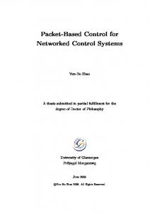
In 2008, OpenFlow [31] was presented to provide a system for testing experimental network protocols in existing networks for researchers. The concept describes the augmentation of Ethernet switches with a flow table and an interface to change this table. The flow-table stores a set of rules concerning the relay task in the switches. The actions supported by these switches are forwarding instructions, encapsulation, and dropping of frames. By this, depending on IP address a switch may relay a frame to different ports defined by the flow-table or drop the frame based on TCP destination port. The adjusted switch design is presented in figure 3.1. The centralized controller uses the OpenFlow protocol to change the flow table in the switch via the well-defined interface and a secure channel. When performing relaying tasks, the switch checks the flow table for matching entries and executed the actions defined in the table accordingly. If no matching entry is found, the standard relaying is used. By this, the controller can adjust the networking routes during runtime. In the past years, the OpenFlow system has achieved a significant popularity resulting in a range of vendors supporting OpenFlow in their network devices. Updates of the system also allow a hybrid configuration where only some ports of the switch get a flow table assigned. [33] The number of recognized fields in headers increase with every new version of OpenFlow as shown in Table 3.1.
18
3. Related Work
Controller
OpenFlow Switch Secure Channel
OpenFlow Protocol
Flow Table
Figure 3.1 The basic concept of the OpenFlow switch as described in [31].
OF-Version 1.0 1.1 1.2 1.3 1.4 1.5
Date December 2009 February 2011 December 2011 June 2012 October 2013 December 2014
12 15 36 40 41 44
– – – –
Header Fields including Ethernet, IPv4, TCP including inter-table metadata including IPv6 including IPv6 extension headers
Table 3.1 The supported fields in OpenFlow by version. (This is based on [14])
3.2. Smart Packets
19
HOST P
Network Management Program
ROUTER
D
IPC
D
HOST D
ANEP Daemon/ Virtual Machine
Network
Figure 3.2 The basic concept of the Smart Packets from [38].
The OpenFlow system is working for changing the relay plane of the network but lacks in support for more actions depending on the frames payload as we want to achieve. Therefore, it can be used for relaying the control signals based on specific flows (e.g., use a different route for specific devices) but no control responses can be generated.
3.2
Smart Packets
The Smart Packets project was inspired by the concepts of Active Networking and uses basics of that architecture. Smart Packets propose to use messages in the network containing code that can be executed by network devices. A computer sends a message using traditional protocols like Ethernet and IP to another computer in the network. In the payload of the IP packet the Active Network Encapsulation Protocol (ANEP) packet is embedded which itself has a Smart Packet payload. The Smart Packet can be of different type. Defined types include Programm Packets which contain programs for execution and Data Packets for data transfer (e.g., for sending the result of a program to the source). Figure 3.2 shows the basic concept of these Smart Packets used in the network. The host uses the Network Management Program which communicates with a virtual machine. This virtual machine (also called ANEP Daemon) uses the network interface to send and receive messages. It can send a Smart Packet to another host also containing the virtual machine where the program contained in the packet is executed. By setting a flag in the Smart Packet header, the program gets executed by every router with the virtual machine that is traversed on the path to the other host. The virtual machine prevents programs to perform damaging actions to the router or the host executing the program. In addition to the virtual machine, the ANEP header includes a certificate for authentication of the sender to the device. The use of protocol headers and certificates reduce the maximum payload in Ethernet environments to about 1 kb for the program. The program is transmitted using
20
3. Related Work
Ethernet Header
SP = 0x0 PUSH [QSize]
SP = 0x4 PUSH [QSize] 0x00
SP = 0x8 PUSH [QSize] 0x00 0xa0
SP = 0xc PUSH [QSize] 0x00 0xa0 0x0e
Other headers (e.g., TCP/IP)
Packet memory is preallocated. The TPP never grows/shrinks inside the network.
Figure 3.3 A Tiny Packet Program that is querying the network. (Taken from [20])
Spanner – a CISC assembly language. Users can write this program directly or use Sprocket which is a high-level language that can be compiled to Spanner. The Smart Packets concept only targets hosts or every router in between the two hosts with a limited program length. The use of a virtual machine protects the host system but also may introduce additional delay for processing. [38] Such virtual machines can add delay to the network which is something we aim to reduce. Further, Smart Packets can only be executed on end-hosts and routers while network switches are not targeted as in our approach. Smart Packets enable the usage of the network for computations and observations but adding control by Smart Packets is only possible if the devices provide an additional framework on their own enabling control which can be programmed arbitrarily by the Smart Packets. Therefore, this concept shows the possibility of augmentation fo network devices but is not suitable for our problem statement.
3.3
Tiny Packet Programs
The idea of Tiny Packet Programs is similar to the one presented by Smart Packets. Instead of allowing arbitrary code to be executed in the network devices, Tiny Packet Programs support only a small set of instructions for code execution aligned to the capabilities of a small network device in the data plane. These programs can be used to outsource computations and storage to network devices supporting this architecture. The packets have standard Ethernet headers with an adapted payload. Instead of adding packets like IP the program is inserted. It consists of a header, a set of instructions and an additional that is used as memory. The program is followed by other packets like IP. Figure 3.3 shows how the Tine Packet Program (TPP) [20] can be used to gather information about the network. The host on the left transmits the packet to the next switch. The blue area in the packet denoted the list of instructions for the devices –
3.4. P4
21
in this example only one operation. The green area is a memory that is provided to the program. The flags in the header (rose area) describe how the memory should be used. The sender can decide whether the memory is handled like a stack or in a different way. In this example, a stack-like memory is used and the SP-flag indicates the stack position. By traversing the network to the host on the right, every device executed the program and stores the data in the packet. The instruction list stays unchanged and the memory area is not resized on the path. The programs can access the memory in the packet to provide results and access the internal memory of the network device to store data that was sent. Referencing registers and common memory positions, a user can collect statistics about the network by sending one packet. Additionally, the devices get assigned an identifier allowing different programs in the same packet for different devices (e.g., store different data in different devices). The devices are augmented with a tiny CPU (TCPU) that executes the TPP or ignores the packet if no TPP is detected. Tiny Packet Programs allow flexible usage of the network devices and can configure them as well by storing data in their memory. To use TPP, all network devices need to get a unique identifier attached and a traditional network device should be avoided in a path where TPPs are used. The TPPs are inserted between the Ethernet header and the payload. The adaption of the Ethernet payload for TPPs can result in problems if devices in the network cannot handle TPP (e.g., traditional Ethernet switches) needing all devices in the network to be TPP-aware. The TPPs are designed to work with a limited instruction set directly on the device. Therefore, the generation of control responses is not part of this concept. Depending on the instruction set, a flexible programming of a network device may be possible but leads to significant overhead and possibly sending small operating systems via TPP through the network being massive overhead.
3.4
P4
P4 [14] describes a language for Programming Protocol-Independent Packet Processors which is designed to work with SDN approaches like OpenFlow. One major advantage of this approach over the standard OpenFlow is the flexibility due to the independency of protocol support implemented into the device. While OpenFlow devices only support a subset of protocols and header fields used in networks, P4 does not require specific protocol support for network devices. Instead of the network device supporting recognition of a protocol and its headers, the controller needs to define the protocol headers and field definitions. The basic concept is shown in Figure 3.4. A packet is received at the input of the switch and the parser uses the parse graph from the switch configuration implementing a state machine. Reading the packet bit-wise the parser changes the state of the machine depending on the values read. Using the results, the switch can check for matching rules and perform the corresponding actions. These match+action operations can be done sequentially or in parallel in the Ingress or Egress pipelines.
22
3. Related Work
Figure 3.4 The basic model of a switch according to the P4 parser concept. (This is taken from [14].)
Instead of using a fixed parser as in OpenFlow, P4 proposes a parser that can be configured during runtime. For this, the controller needs to define the protocol headers including their fields first. Additionally, the controller defines the parser operations using a transition function which is evaluated by the parser when reading the input packet. An example of such a configuration is shown in Figure 3.5. The controller provides definitions for the headers of Ethernet and VLAN (IEEE 802.1Q) including the fields and the number of bit per field. The lower half describes the transition function for the state machine. The parser starts with state start, goes directly to the ethernet state which also means to read the first bytes and cast the data according to the ethernet header definition. Depending on the ethertype the next state and header representation is chosen. This is a simple example with only two header definitions and three states. Adding more headers can be done without changing the other definitions or the network device. In addition to the definition of headers and the transition function, a P4 program contains tables describing the match+action operations for packet processing. The action that should be performed can be simple predefined actions like replacing header values but also complex operations that are defined in the actions part of the program. Finally, control programs are added to the P4 program. These control programs describe the order of match+action tables have to be applied. To bring the P4 program to the data plane, a compiler is used that converts the parser information into a parser state table that allows the parser to read the incoming packet bitwise and evaluate the state. The control programs are analyzed for optimizations regarding dependencies and compiled into different configurations depending on the
3.4. P4
1 2 3 4 5 6 7
23
header ethernet { fields { dest - addr : 48; src_addr : 48; ethertype : 16; } }
8 9 10 11 12 13 14 15 16 17
header vlan { fields { pcp : 3; cfi : 1; vid : 12; ethertype : 16; } } // more headers in here
18 19 20 21
parser start { ethernet ; }
22 23 24 25 26 27 28 29
parser ethernet { switch ( ethertype ) { case 0 x8100 : vlan ; case 0 x800 : ipv4 ; // More cases } }
30 31 32 33 34 35 36
parser vlan { switch ( ethertype ) { case 0 x800 : ipv4 ; } } // more states in here
Figure 3.5 An example for configuring the parser state machine in P4. The example is based on [14].
24
3. Related Work
target device (e.g., a multicore-system can be treated differently than a fixed-function switch). The concept of the P4 language allows network managers to change the behavior of the network depending on header values without having a fixed parser with limited capabilities for recognizing protocols. The language is simple and the compiler generates results for configuration for different devices. Switches being programmed with P4 are not designed for changing the payload of a packet but by misusing the header definitions a user could change the payload but this needs to be examined further. The concept of P4 allows editing the current packet but not the generation of additional frames which are supported by our approach.
3.5
EtherCAT
A popular approach for control systems in the last decade is the EtherCAT [17] system. It was developed by Beckhoff Automation and is a fieldbus system based on Ethernet aiming for real-time, short data update times at reduced hardware costs. In Ethernet, a frame has a minimum length of 84 bytes (including the Inter-Packet Gap of 12 bytes). Observing an example of a station that needs to (cyclic) send status information of 4 bytes and a controller sending control signals of 4 bytes, assuming there is no time needed for transmission (100 % usage), the effective data 4 = 4.7%. Taking non-ideal usage into account, the data rate is reduced rate is 84 further. This is a major problem for real-time applications with multiple participants sending/listening for frames. The EtherCAT system uses a master/slave approach in communication. Each period, the master creates a new frame that is sent along the topology of the network. Instead of using one frame per slave, all slaves parse the frames on receiving, extracting matching control information and adding their data to the frame on-the-fly. The EtherCAT protocol frames, are standard Ethernet frames with the EtherType header set to EtherCAT protocol. The payload consists of an EtherCAT header and the EtherCAT datagrams, which consist of a header and data payload. The structure is shown in figure 3.6. The slaves check the datagrams, store the matching information and alter the datagrams in case a datagram ist determined for its data. In the example from above, EtherCAT can lead to an effective data rate of more than 90%. The concept of master/slave with devices on-the-fly reading and changing the frame is similar to the concept of I2 C described in section2.4. In addition to the real-time approach in a local network, the EtherCAT system can operate with different networks (connected via standard routers) by encapsulating the EtherCAT frame in IP/UDP additionally. Further, EtherCAT supports special operation modes like Ethernet tunneling, CANopen over EtcherCAT or Servo Drive over EtherCAT. [12] By this, EtherCAT presents a way to use a Networked Control System with apparently commodity network devices allowing a high performance and guarantees. But the EtherCAT slaves need a special set of hardware features including a separate slave controller. [13] EtherCAT bases on Ethernet and connects all devices
3.5. EtherCAT
25
Ethernet Frame
Destination
Source
EtherType
Payload
CRC
EtherCAT Frame
Header
...
Datagram 1 Datagram 2
Datagram n
EtherCAT Datagram
Header
Data
Figure 3.6 The EtherCAT datagrams consist of a header and the corresponding data. Multiple datagrams are enclosed by an EtherCAT frame header forming an EtherCAT frame. The EtherCAT frame is encapsulated in a standard Ethernet frame with fixed EtherType. (based on [15])
26
3. Related Work
Application Userspace
control
miss
Kernel
TRANS
hit
Cache
NET Kernel Hardware
MAC Figure 3.7 The concept of SANTA as described in [37].
with other devices. The EtherCAT approach uses a master/slave design which is a cyclic execution that does not support event-based concepts. For large facilities, EtherCAT introduces challenges by the maximum transmission unit leading to the need for several segments. The problem gets more serious when adding security headers and encapsulation to these frames. Further, the amount of data that needs to be sent by a device may change in size, so the reserved bytes in the frame may increase further. By this, EtherCAT transforms parts of the traditional systems into more commodity devices in industry control introducing several problems for distant controller design.
3.6
SANTA
To reduce the delay in a system’s network stack introduced by memory operations and the need for context switches the SANTA [37] approach was proposed in 2015. The network stack uses an application agnostic cache for frequent requests. Inside the kernelspace, the system can check the incoming frame against data in the cache. If a matching entry in the cache is hit, the response is generated accordingly in the kernelspace and sent without need of handing over to the application layer. If there was no matching cache entry found the system hands over the data to the application layer as in an unmodified system. The applications in the system control the cache and provide feasible entries. This concept can be seen in figure 3.7. SANTA is designed for end-hosts running Linux which in our scenarios only reduce the delay in the network introduced by the network stack in the controller. For distant controllers this improvement becomes negligible. Our idea is similar to the concept of the application agnostic cache in SANTA but allows the attachment to network devices in general while SANTA targets end-hosts. Further, SANTA lacks in support for more complex condition checks, processings, and wildcard checks like we are aiming for.
4 Design In the previous chapters, we gave an outline of the basics of control systems and concepts to combine the control theory with networks as well as approaches augmenting the network devices. The current approaches have problems when applying to the vision of a distant controller. We want to tackle these problems by using our own concept augmenting the network. In this chapter, we consider the problem of network delay in more detail first. Then we present our basic concept of rule-based augmentation. Using this concept we define setups for measurements and simulations we will evaluate in the next chapter. Intuitively, we propose a concept of augmenting network devices for outsourcing distinct parts of the control into the network. The network device (e.g., a switch) can parse the frame and check the protocols used, source, destination and payload against rules stored in the device. When matching such a rule, operations can be performed, including changing the payload, relaying or even generating and sending multiple frames. For flexibility, the switches can be programmed with such rules during runtime using standard network protocols.
4.1
Problem Statement
In Figure 2.4 we show an abstract model of a general Network Control System. The sensor output y gets delayed or lost in the communication channel resulting i in the delayed sensor information w. The delay of sensor i is given by τsc (t) (see Equations 2.5 and 2.6). Using a distant cloud connected via the Internet introduces indeterminism and protocol overhead like ARP in the local network and DNS queries occuring for messages sent over the Internet. Therefore, considering traditional networks using protocols like Ethernet, 802.11, IP and UDP we can not give a definite upper bound on τscmax . In the general Networked Control System model, the communication channel is treated like a black box. In our scenario, we make use of traditional network protocols
28
4. Design
P
Switch
P lant
Router
P
Switch
Controller
Figure 4.1 An example of a network consisting of two clients, a router, two switches and several cables. Application
Application
Presentation
Presentation
Session
Session
Transport
Transport
Network
Network
Network
Data Link
Data Link
Data Link
Data Link
Data Link
Physical
Physical
Physical
Physical
Physical
Figure 4.2 The network view of the example of Figure 4.1. The network devices can have different components of the OSI network model stack that have to be traversed by a message.
and models. A traditional network may consist of multiple routers, switches, cables and antennas which are traversed by a signal depending on the selected route. Figure 4.1 shows an example of a network connecting a plant and a controller via traditional network devices. The information is sent along multiple Ethernet links and is being processed in network devices such as switches and a router. In Figure 4.2 we show the network regarding the network stack of the devices. We describe the components and the delay introduced by them in Table 4.1. We can represent a end-to-end message transmission time in the network connection by ∆ = Tsend +
X ∀s∈S
s Tswitch +
X
r Trouter +
∀r∈R
Description Application sends data via Socket Frame is delivered via Link Processing of packet in Switch Processing of packet in Router Application receives data from network card
X
l Tdelivery + Trecv + Tmisc
∀l∈L
Color in Figure orange green blue magenta red
Symbol Tsend Tdelivery Tswitch Trouter Trecv
Table 4.1 Types of delays introduced in a traditional network for packet delivery
(4.1)
4.2. Basic Concept
29
where S denotes the set of all network switches, R the set of all routers and L the s describes the set of all network links on the path the data is transmitted over. Tswitch l r processing time in switch s. We define Trouter and Tdelivery analogously. Depending on network links, the data cannot be transferred directly but needs to be scheduled. Such scheduling delay occurs when a link is used at the moment, medium access protocols assign slots for transmissions, a link is temporary unusable (e.g. due to interpacket gap) or protocols like ARP need to be executed first. This introduces additional overhead given by Tmisc which is hard to estimate. Assuming Fast Ethernet, we can describe Tdelivery by Tdelivery =
packet size distance + bit rate propagation speed in cable
(4.2)
Using the maximum transmission unit of 1500 bytes and maximum cable length of 100 meters, the frame delivery time is given by 120, 5µs which denotes the upper bound for the frame delivery time in Fast Ethernet. [19]
4.2
Basic Concept
In a production facility scenario, the time between a device A sending a message and (possibly another device B) receiving control signals based on the descisions of controller C this can be described by ∆ACB = ∆AC + TApp + ∆CB
(4.3)
where ∆AC is the end-to-end transmission time for device A sending data to controller C. Analogously, the transmission time from controller to device B is given by ∆CB . Between receiving the data in application layer of the controller end sending the corresponding response calculations are needed. This delay is defined by TApp . Concerning Networked Control Systems as defined in Section 2.6 we can set τsc = ∆AC and τca = ∆CB . In contrast to the NCS we also model the processing time TApp in Σcontroller . Beside processing times and transmission times, the upper bounds τscmax and τcamax depend on the protocols used. In this thesis we focus on Ethernet (IEEE 802.3) for the link layer, Internet Protocol (version 4) for network layer and User Datagram Protcol for the transport layer. This allows us to use assumptions like transmission time assumptions while avoiding complex state machines and connection handling processes like in the Transmission Control Procotol. Additionally, we use the Wireless LAN (IEEE 802.11) protocol and hardware during our work with the WARP boards in Section 5.2. In our approach we want to reduce ∆ACB significantly because in a scenario of a distant controller the values become quite high and undeterministic. Therefore we adjust the network devices. These devices should perform simple actions based on the frame that is relayed by them. To describe these actions and the frames that should trigger such actions we define a simple data structure and an execution engine. These are described in detail in Sections 4.3 and 4.4. This approach is similar to the
30
4. Design
concept of reflexes in the human body, where triggers (e.g. bright light) cause quick reactions (e.g., blinking) – therefore we call it Reflexes. In a production facility, such a reflex can be the reaction on events occuring that need a reaction. An example is a temperature sensor sensing a temperature higher than desired and a reflex sending control signals to heating devices to stop or a robot arm to move away from the source. This is similar to a person sensing high temperature at the hand resulting in a reflex moving the hand away. Adapting Delay Equation According to our approach, we adjust the delay equation. The processing of a frame in a network switch or router that checks, whether a reflex needs to be executed differs from simple vanilla relay tasks in this device. We denote these processing r s times by TRef lexSwitch and TRef lexRouter . SRef lexes = S \ SN oRef lexes is the set of all switches in the network path with enabled reflex execution engine. RRef lexes is defined analogously. For notation, we describe the vanilla approach as presented before using ∆ while ˆ for transmission times occuring in a network with reflexes-enabeled devices. using ∆ ˆ Exec denoting transmission time if the network Additionally, we distinct between ∆ ˆ N oExec describes the has reflexes-enabled devices and a reflex is executed while ∆ path without reflex execution but reflexes-enabeled devices. In case of a message that is not triggering any reflex, but traverses devices with enabled reflex execution engine we can describe the end-to-end message transmission time by
X
ˆ N oExec = ∆
s Tswitch
∀s∈SN oRef lexes
+
X
s TRef lexSwitch
∀s∈SRef lexes
X
+
r Trouter
∀r∈RN oRef lexes
+
X
(4.4)
r TRef lexesRouter
∀r∈RRef lexes
+
X
l Tdelivery
∀l∈L
+ Trecv + Tsend + Tmisc The processing time in a network device with activated reflex execution engine will s s add processing additionally to the relay tasks, so it holds TRef lexSwitch > Tswtich for the same device. THis means that the activation of reflex execution engine will increase the total delay if the message traversed this device. This holds analogously ˆ N oExec > ∆ assuming Tmisc being independent. In practice, for routers and leads to ∆ it is possible that the relayed frame needs to be enqueued. The time waiting due to enqueuing can exceed the extra processing time and by that leads to Tmisc being
4.2. Basic Concept
31
dependent on the processing times of the reflex execution engine. This also leads to s s ˆ TRef lexSwitch ≥ Tswtich and ∆N oExec ≥ ∆. ˆ N oExec Concerning processing time in the case of a reflex execution, the equation for ∆ has to be adjusted again. One of the network devices (e.g. switch s ∈ SRef lexes ) will not simply check for matching reflex rules and relay the frame but also processes the frame according to the whole rule execution engine including frame generations. We describe the resulting processing time in this device as Tref lex . For simplicity we define sets S 0 and R0 being the sets of switches and routers traversed in the network path until the reflex execution excluding the executing device itself. Their subsets are defined analogously. Further, executing the reflex in the network before reaching the controller leads to fewer network links to be used. Therefore, L0 ⊂ L is the set of network links that are traversed by the message in this case. By that, we can describe the transmission time from sender to reflex execution by X
ˆ Exec = ∆
s Tswitch
∀s∈S 0 N oRef lexes
+
X
s TRef lexSwitch
∀s∈S 0 Ref lexes
X
+
r Trouter
(4.5)
∀r∈R0 N oRef lexes
+
X
r TRef lexesRouter
∀r∈R0 Ref lexes
+
X
l Tdelivery
∀l∈L0
+ Tsend + Tmisc In total, for a message sent by device A to the controller C using a (reflexes-aware) network and receiving the corresponding response in device B the time needed is given by ˆ ACB
∆
� =
ˆ CB ˆ AC + Tref lex + ∆ ∆ Exec Exec ˆ CB ˆ AC + TApp + ∆ ∆ N oExec
N oExec
if reflex executed otherwise
(4.6)
The path that is traversed until execution in reflex execution engine for the message sent by A is shorter than in case the controller is receiving the message. Hence it ˆ AC < ∆ ˆ AC ˆ AC . Regarding the path from C (or the intervening holds ∆ Exec N oExec ≤ ∆ network device) to device B we cannot give absolute relation. It depends mainly on the network topography and the selection of the network device that gets assigned the corresponding rule. Futher, it is possible to apply rules to perform actions inside the facility independent from the controller. For example, a switch may generate a copy of a frame sent to the plant and send it to a local oberserver terminal. This would also affect the response time. P Figure 4.3 shows a sample network with switches, a router, a controller ( P lant ) and the devices A, B, C and D. Assuming, a reflex rule reacting to the message from A
32
4. Design
E A switch 1
P
P lant
switch 2
router B D
Figure 4.3 The selection of the network device that is supposed to perform reflexes has impact on the total processing times. Selecting switch 1 or switch 2 for a reflex lead to different results.
to the controller by sending a message to B needs to be assigned to a network device. When using switch 2 for this, the transmission times become rather small, yielding AC CB CB ∆AC Exec < ∆N oExec and ∆Exec < ∆N oExec . But if the reaction requires a message CE to device E instead of B, it holds ∆CE Exec > ∆N oExec . A simple selection concept would be to use the nearest possible switch for each message possible. Regarding a large set of possible messages and reactions for A, switch 1 would need to store a high number of rules and check incoming frames against all of these. This leads to more time needed in the switch, increasing Tref lex . Furhter, a higher number of rules and commands can exceed the capabilites of network devices. So there is also need to select the messages the network should react to. By reasonable selection, the response time for specific messages can be reduced while slightly increasing the response times for other messages. In this thesis we do not focus on strategies for selecting the devices and rules to be used. We distinguish between different subtypes of these reflexes. The na¨ıve reflexes will simply check the incoming frame matching a rule, generate pre-defined frames based on the rule and send them. This is rather simple and is similar to caching approaches like Santa. [37] We also allow rules to copy and replace fields and payload when relaying or generate new frames based on the field of incoming frames. This allows the device to generate responses while sending the original data with comments and additional information to the controller. When adding a runtime generated ID during this process and attaching it to the messages, the controller can send refine instructions. By that, a device can e.g., instruct an actuator to move in a certain direction while the controller sends detailed information about the target position later. At last, the augmentation also enables the devices to perform basic operations, that need to be defined at design-time. This allows these devices e.g., to execute different reflexes depending on the range of temperature information or convert data from imperial to metric system. In this thesis, we will use all of these subtypes and show their applicability.
4.3
Data Structures
To reduce extra processing times introduced by reflex execution we enable network devices like switches to perform small actions. These actions are defined by a rule
4.4. Reflex Execution Engine
33
structure. The Rule has fields for protocols, source and destination regarding network stack layers two to four. Additionally, the payload is represented by the content field. This Rule structure is used to represent frames and provides an abstraction layer for operations like matching and replacing values. To describe the actions that have to be performed on activating a reflex the Rule has a set of ExecRules. These contain the information which source and destination values have to be set in the frame that gets generated as well as its payload. Depending on the value of the Rulenumber field the reflex execution also checks the Condition and ProcessingCommand fields of the ExecRule. This abstraction layer including several supporting methods for matching, replacing or executing predefined operations result in code that can be used for every device, independent from the systems internal handling of frames. To connect a device and the abstraction layer, an adapter is needed. The main tasks of the adapter contain the generation of a Rule data structure based on the frame that enters the system and the generation and transmission of frames from ExecRule structures. This is similar to the approaches of software defined networking as presented in Section 2.7. To add rules to the network device with augmentation normal packets are used. They contain a payload including the identifier of an device known to the specific execution engine. When receiving the frame, the engine checks, whether this programming message is meant for this device and imports the rules from the payload. In this thesis, we use a simple plaintext representation and no verification of the source. This introduces security issues in case of a malicious network device sending programming frames for e.g., generate copies of all messages in the network and sending them to a server or even perform damaging actions. Augmentations for security issues are possible (e.g., like used in OpenFlow [33]) but not in scope of this thesis. We show the applicability of this abstraction and adapter approach by using it in different systems and programming languages during this thesis.1
4.4
Reflex Execution Engine
The above mentioned data structure and the adapter in a network switch build the reflex execution engine augmenting the device. We define the way the reflex execution engine will process an incoming frame in this Section. In Figure 4.4 we present the concept of the Reflex Execution Engine using a simple flow chart. This engine is called from the MAC layer and needs to return a boolean indicator whether the execution was successful. If the execution was unsuccessful (e.g., when the device has no matching rules) the device processes the incoming frame further independently from the engine as if there was no augmentation. To determine the successfulness of the execution, the engine is wrapped in a small function that evaluates the return value of the execution and hands over the frame to the device for normal processing or manages the deletion of the buffer and end of processing for the frame in the device. 1 We implement these structures using classes in object-oriented languages like C++ and C#, while using structs in C
34
4. Design
MAC Layer
Reflexes Enabled?
Generate Rule representation of frame
Return false
Return true
Rules (local) Return false Add Rules Generate Rule representation of frame
For Me?
Progr. Frame?
Return false
Access & copy
Matching Rule?
For each ExecRule in Rule
Replace Placeholders
2
Rulenumber?
3
Replace Placeholders
1 Generate Frame from ExecRule
Command defined?
Condition defined?
Return false
Send frame
Next ExecRule
Execute Command
Condition?
Command defined?
Return true
Figure 4.4 The flow chart of the reflex execution engine, when receiving a frame. Diamonds indicate conditions that change behavior and flow (red arrows mean condition was evaluated to false).
4.4. Reflex Execution Engine
35
At first, the engine checks whether the reflexes system is activated (e.g., a flag is set). If the system is enabled a representation of the incoming frame in the abstraction layer is generated. This rule representation allows the abstraction layer to work independent from the data structs and protocols used inside the containing network device’s system. The engine checks this rule for being a reflexes programming frame (diamond Progr. Frame?“). If this evaluates to true, the target engine is checked. ” In case of matching identifiers, the system interprets the payload of the message and adds the rules to the local storage before returning true to avoid further processing or relaying of the frame. Frames being no programming frames result in the rule representation to be checked against the rules in the local storage. The fields are checked for that purpose. They need to be the same or the same until a wildcard indicator in the local rule for every field. In case a matching rule was found, this rule is copied and the engine will iterate over the execution rules in it (dashed box). The rule is copied for simplicity because the execution may replace field values before generating frames based on the execution rules. The processing of the execution rule depends on the rulenumber identifier. For now, we defined three different identifiers indicating different handling. The rulenumber 1 leads to the simple processing only consisting of generating a new frame based on the fields of the execution rule and sending it. With rulenumber 2 there is some additional processing needed: Before generating the frames for transmission, placeholders (e.g., for Payload or original IP Destination) are replaced by the corresponding values. The most complex process is given for rulenumber 3. First, placeholders get replaced. Then the engine checks for conditions being defined and evaluates those (e.g., first number in payload below value 200). A condition that is not met, directly results in returning with exit code for unsuccessful execution. In the next step, the engine checks the field representing the processing command. If this is set, it executes the defined commands (e.g., convert degree Fahrenheit to Celsius). By checking conditions defined by the Condition field or executing commands defined by the Command field, this execution does not result in a frame generated for sending. This enabled the system to perform multiple actions and checks before sending by traversing multiple execution rules after each other. After all execution rules are traversed in the engine, the execution ends and the corresponding code is returned. We show the applicability of this reflex execution engine and evaluate its processing time in the next chapters.
36
4. Design
5 Measurements and Simulations In the previous chapters, we described the problem of the delay in networks and presented our approach to reduce this delay for some messages by adding some control logic to the network itself. In this chapter, we present measurements of vertical delay in a Unix commodity system and implement the reflex execution engine for a network device. We build simulations in which we use the results of our measurements and other researchers to investigate the impact of the delay in production scenarios. We add our system to these scenarios measuring the effect we can achieve in them and evaluate the feasability of our approach by these simulations.
5.1
Vertical Delay Measurements
In Section 2.3 we describe the network stack in Linux/Unix and the problem that it is introducing delay to the processing. To characterize this delay we perform simple measurements. In production facilities often general purpose commodity systems (e.g., Windows PCs) are used for many tasks. Therefore we decided to perform measurements with a commodity device instead of highly optimized special-purpose systems. For this, we use a commodity computer running a Unix system.1 For measuring we use the tools libpcap/Wireshark [8] that are using the system’s kernel timestamping methods when a frame is received. [35] For characterizing the network stack processing times, we created two simple applications. The server application sends a message of defined size to the target computer every 0.5s. The client application on the target computer opens a socket and listens for incoming messages. Both applications will create a timestamp in the moment of sending/receiving a message. These applications run in the userspace inside the mono runtime environment, which provides optimized handling for binding and handling the network stack API in userspace. For this scenario, we use IP (version 4) and UDP as protocols. To compute the processing time, we use the difference of 1
In Detail: A MacBook Pro (2013) with macOS Sierra (Unix)
38
5. Measurements and Simulations
Application
Timestamp
Network Stack
Driver
Timestamp
Hardware
Figure 5.1 A frame is received at hardware level and handed over to the driver in kernelspace, where the pcap library creates a timestamp. The data is handed over to the application layer, where an application waits for this data and performs the next timestamp. The difference of these timestamps is regarded the processing time in our measurements.
Ethernet WiFi
Send 149.76µs 187.19µs
Receive 150.92µs 115.98µs
Table 5.1 Median values for sending and receiving messages via Ethernet and WiFi accumulated over all message sizes.
kernelspace timestamp (pcap) and the application layer. This is shown in Figure 5.1. The tests are performed using Ethernet and again with WiFi. We performed the measurements for sending and receiving on the test computer with payloads of different sizes from 12 bytes (only an identifier) to full MTU. The results are shown in Figures 5.2 and 5.3. We closed the applications on the machine except the capturing applciations and the background and operating system tasks that were running on the machine. This yields a not perfect system but fair commodity system with the main tasks of listening for messages. Due to this, the network interface was not faced high load but only a number of small number of frames per second (less than 50 frames per second) for system tasks. The results do not show a clear and general connection of the processing time and the frame size. Measurements of the time needed for receving a frame via WiFi seem to grow with the size of the frame but using the same adapter for sending, the results do not show such a connection. Wecan die similar observations for the Ethernet network interface usage. Further, the results of the Ethernet measurements present a smaller range of median and mean values than the WiFi results. The results show that the size of the payload has less impact than other factors.
5.1. Vertical Delay Measurements
39
Network Stack Processing Times (Eth)
400
Processing Times in µs
350 300 250 200 150 100
Measurements
MTU (S)
MTU (R)
1000b (S)
1000b (R)
500b (S)
500b (R)
12b (S)
0
12b (R)
50
Figure 5.2 Results of the measurments of the vertical network stack delay for Ethernet. The notches represent median and red squares mean values.
40
5. Measurements and Simulations
Network Stack Processing Times (WiFi)
400
Processing Times in µs
350 300 250 200 150 100
Measurements
MTU (S)
MTU (R)
1000b (S)
1000b (R)
500b (S)
500b (R)
12b (S)
0
12b (R)
50
Processing Times in µs
Figure 5.3 Results of the measurments of the vertical network stack delay for WiFi. The notches represent median and red squares mean values.
460 440 420 400 380 360 340 320 300
Processing Times (Rich Client)
Measurements
Figure 5.4 Processing time from receiving a message to sending a response in a rich client computer.
5.2. WARP Implementation
41
Table 5.1 shows the median values of the tests for sending and receiving the messages using Ethernet and WiFi accumulated over all payload sizes. The difference between sending an receiving in Ethernet is very small but in case of WiFi there is a significant difference. The results are connected to Tsend and Trecv as defined in the design chapter. In our next test, a computer sends a message to our observed computer. This observed machine has to process the message, perform some basic operations (string conversion, replacement) and send a response to the first machine. Again, we use timestamping for our measurements. The first timestamp is taken in the driver when receiving the message while the second timestamp is taken in the driver when processing the outgoing response. This is a simple version of a controller reacting to a message from the plant. The results are connected to Tsend + TApp + Trecv as defined in the design chapter or Tsend + Tref lex + Trecv when using a client as network device on the network path. Figure 5.4 shows the resulting processing times from the test described above. The major part of the processing time is the vertical network stack delay. The operations in application layer on the data are performed fast in comparison to the overhead of context switches and process scheduling in the operating system. The times in the results are higher than the optimized Linux kernel measurement presented by Larsen et al. [24] of less than 10µs for receiving or sending. Other measurements like the ones in [18] present times higher than Larsen et al. but less than our measurements. Therefore we can use our measurements for a reasonable slow multitasking commodity hardware controller and the results from Larsen et al. for fast high-performance controllers.
5.2
WARP Implementation
To reduce the vertical network delay, we implement the reflex execution engine for a specific network device. We decided to use a WARP board. [5] In detail, we use a WARP board of version 3 and extend the 802.11 reference design (provided by Mango communications [3]) which are described in Section 2.8. The WARP board architecture allows us to transfer parts of the control logic from a device with complex network stack as described in Section 2.3 to a small device with limited capabilites and network stack. We explore the effect when adding such logic to the highest layer of the network stack in this device. For our tests, we add the reflex execution engine to the CPU high framework for Access Point management while using the DCF version of the CPU low framework. This allows us to perform measurements of the station (de)association process and provides easy and flexible connections for our devices. Figure 5.5 shows the simplified interaction between the CPU low and CPU high frameworks for frame processing. In the reference design (figure 5.5(a)) the CPU low takes the frame, performs some checks, stores the frame in a buffer and mailbox and triggers the interrupt using a set of special ports for this process (so called mailbox). The CPU high executes the interrupt service routine and calls the mpdu rx process(..) method to process the frame. In this method, the FCS
42
5. Measurements and Simulations
CPU Low
Receiving, Data in buffer
CPU High
CPU Low
Receiving, Data in buffer
WarpBoard Mailbox
Interrupt
CPU High
WarpBoard Mailbox
Interrupt
mpdu_rx_process(..)
mpdu_rx_process(..)
Check flags, FCS, destination...
Check flags, FCS, destination...
Relay, association...
Reflexes Execution
Relay, association... Preparing frame(s) for transmission
Polling, transmitting
Preparing frame(s) for transmission
Polling, transmitting
(a) Vanilla
(b) With Reflex Execution Engine
Figure 5.5 The processing of a frame in the WARP board 802.11 reference design. The lower Figure shows the adaption for the reflex execution engine.
and destination is checked before processing further. Depending on the frame, (de)association is performed with respect to the corresponding state machine and updates the list of associated stations if needed or the frame is delayed to the destination. In case of a frame is generated and needs to be sent, it is stored in a buffer (using the mailbox again) and setting a flag for the CPU low which transmits the frame when polling the data (depending on selected framework with or without DCF support). Adding the reflex execution engine is done in CPU high after the checks are performed (figure 5.5(b)). Due to the execution of the engine, it is possible that multiple frames are prepared for CPU low in CPU high. Due to polling in the CPU low transmission of the first frames is started before the CPU completed the execution of frame processing. The buffers for incoming and outgoing frames are guarded by mutexes shared with both CPUs. The reference design also supports the use of Ethernet as well as WiFi to provide bridging. This is done in software by the ethernet encapsulation in the CPU high framework. For simplicity, we use this concept and perform this after generating the frames in the execution engine. The resulting frame is handed over to the CPU high method for sending such frames including scheduling, setting buffers and flags. For our tests, we only used rules with rulenumber 2 that need to replace values depending on the incoming frame but does not need to perform complex commands, which are independent of the system we are using. We connect multiple devices via WiFi to the WARP board and capture the outputs of the CPU high. The processing times we measure are given by the time differences in the CPU high between jumping into mpdu rx process(..) and leaving this method. This possibly adds some overhead for determining and storing timestamps as well as special other interrupts that may occur during execution. Figure 5.6 shows the measurement results (means) in detail. The simple processing of a frame (Vanilla) takes only less than 10µs for relaying a frame. The bars for
5.2. WARP Implementation
600
Processing Times in µs
500 400 300
43
Misc Sending Checksums Frame Construction Replace Matching Generation Alloc Non-Reflexes
Processing Times Detail
200 100 0
Vanilla
1 Rule
2 Rules
3 Rules
4 Rules
5 Rules
5 Rules Rule Optimized Execution
Figure 5.6 Results of the measurments of the WARP Board processing times measurements.
1 Rule to 5 Rules denote tests where one to five rules were added to the system. On processing a frame (not matching any rule) the most significant part of the processing time is defined by the matching algorithm (Matching). This algorithm iterates over all available rules and checks every field byte-wise. This results in a high amount of memory operations which are very expensive in terms of time. In consequence, we adjusted the engine slightly with a simple flag. If during generation of a rule representation (Generation) of the frame an unsupported protocol is found, the flag is set, instructing the matching algorithm to terminate early. While the first approach has a scaling problem with the number of rules in the system (∼ 90µs per rule), the adjusted engine drops this problem and results in less processing time for frames that are not matching any rules making the rule generation the most significant part. The right-most bar represents the engine execution if a matching rule was found. Besides rule generation and matching, the replace operations (Replace) including iterating multiple times over all fields and resizing buffers have a significant processing time. Further, the construction of the frame (Frame Construction) and the computation of checksums (Checksums) for Ethernet – CRC32 – and the sending operation (Sending) also need significant time for execution. The small blue line that can be seen in the reflexes-enabled tests (Alloc) denotes the time needed for the allocation of memory for one rule and is added to provide some perspective for memory operations. With a mean time of 3µs the allocation needs nearly as much time as the Vanilla relaying in this system. The measurements of the detailed executions may also be affected by the measurements itself because the timestamps needed to be computed and stored in the slow memory. The Non-Reflexes execution describes time needed before and after the execution of the reflex execution engine. The required times needed for the replacement operations only occur due to the rulenumber defining these operations to be needed. So this time directly depends on
5. Measurements and Simulations
Processing Times in µs
44
480 470 460 450 440 430 420 410 400
Processing Times for (De-)Association
Figure 5.7 Processing time for station (de)association in the WARP board CPU high framework
the amount of content-aware processing that is needed. Using optimized concepts or even rulenumber 1 results in much less or no time needed for this. Checksums like CRC32 can be implemented in hardware which is commonly done nowadays. Using a slightly adapted reflex execution engine or hardware can result in no time needed for this checksum computation. These results connect to Tref lex as defined in the design chapter for reflex execution. The results for processing times in case s no reflex was executed connect to the definition of TRef lexSwitch where s denotes the WARP board.
Another test with the WARP boards targets the station association and deassociation, which also needs some processing during runtime and respects a complex state machine. To put our results from before in perspective to other tasks that are performed using these devices, we perfroms this test. For this purpose, we use three WiFi devices that periodically associate and deassociate to the WARP board running the Access Point management reference implementation in the CPU high. Figure 5.7 shows the results for this test. The association and deassociation require more time than a simply relaying we have seen before.
Figure 5.8 puts the measurements into perspective. On the right side, the station (de)association results are shown. These are faster than the execution of complex reflexes in the reflex execution engine which is presented by the second boxplot from the left. We described how a simple rule without complex replacement operations and checksum computation outsourced to hardware. This is shown in the boxplot on the left side reducing the processing time significantly. For perspective, the third boxplot shows the data from the measurements with commodity computer (Rich Client) processing the message in the application layer in a fairly optimized system with multiple running tasks. For the simulations, we will use the results from WARP board testing as well as the computer tests and results of other researchers.
5.3. Simulations
45
Frame Processing Times
600 Processing Times in µs
550 500 450 400 350 300
Reflexes (Naive)
Reflexes Rich Client (Complex) Measurements
Station (De)Association
Figure 5.8 The results from above put into perspective
5.3
Simulations
To investigate the feasibility of our approach for reducing network induced delay for control tasks we design simulations and use different data for processing times in the network devices and analyze the effects on the control tasks with and without reflexes. For simulations we use the simulator system Omnet++[4] and the INET framework[1] for network protocols and devices support. We augment the Ethernet switches in the framework with the reflex execution engine. By default, the processing times in the network devices is set to zero. For our simulations, we changed the implementations of the switches and client devices to enable the usage of processing times we can insert into the simulation. By that the simulation can not only take times of transmissions (that we are reducing in number) but also processing times (which we are potentially increasing). Figure 5.9 shows the way we changed the Ethernet MAC layer model in the INET framework. In the original version, the control flow traverses the logic link control process and hand over to the next stack layer or use the MAC relay unit if no higher layer is needed or available like in Ethernet switches. We add the Reflexes adapter directly aside the relay unit. The adapter can hook into the relay unit for checking the frames but also uses the medium access layer directly to schedule transmissions of messages. For our simulation tests, we also add some functions for computing the delay induced by processing for each message that is sent. For the simulations, we use different values for processing times. The WARP board simulations use the timings we measured for the vanilla switches and reflex-enabled switches and the measurements with commodity hardware for client systems. The Client simulations use the timings of the commodity hardware for clients as well as reflex-enabled switches. For small timings we use the values from research [24] (Paper) for the switches and clients. At last, tests without processing times (None) are performed and focus on the network links only.
46
5. Measurements and Simulations
NET
NET
MAC Relay
LLC
LLC
MAC Relay
Reflexes Adapter
MAC
MAC
(a) Vanilla
(b) With Reflex Execution Engine
Figure 5.9 The Ethernet layered model architecture in Omnet++ and our reflex execution engine (This figures is adapted from [2].)
5.3.1
UDP Traffic Test
The first simulation we build is a very simple network configuration that can be seen in Figure 5.10. A sensor and an actuator are connected via network switches and a router to the controller. In addition four computers are added and can be used to add noise and load to the network which is not related to the control tasks. In the vision of a distant controller, there are many sources of network traffic that can not be controlled. By these four hosts, we are able to simulate external influences of others to the control system. All network links are modeled as Ethernet 100 MBit/s cables, where one cable of the extra computers is set to 15m while all other cables have a length of 10m. The last modeled link to the controller is set to 0m length simulating the minimal distance of the controller in the scenario. The Sensor and Actuator send messages to the controller with a given frequency. The messages are selected randomly using a fixed seed for the simulation. Depending on the messages the controller sends messages to the sensor, the actuator or both. Two of the switches also have a reflex execution engine. They are marked with their identifier in blue in the figure. Figure 5.11 shows the results of the simulations. The different colors denote the processing time sources that are used as defined before. The plot shows ranges reaching from the minimal to the maximal time elapsed between generating a message and receiving the corresponding response where the dot represents the mean value. The plot is subdivided into four areas describing the results for a network with vanilla switches or reflexes-enabled switches as well as with or without the extra computers adding network load. Different test cases are mentioned. The Full Path test requires a message to traverse the whole network from sensor to the controller and a response from the controller
5.3. Simulations
47
Additional Client
Additional Client Actuator
Switch Switch LateSet
Switch MidSet
Router
Controller
Switch
Sensor
Additional Client
Additional Client
Figure 5.10 The simulation setup for the UDP Traffic Test simulation
0.0035
Simulation Times Paper
Zero
0.0030
WB
Rich
Case Time in s
0.0025 0.0020 0.0015 0.0010 0.0005
Re fl
ex
e fin
rt
Ale
ath ll P
Re
La te
Measurements
Figure 5.11 Response times for the UDP Traffic Test
Fu
ex Re fl
fin
e
Reflexes + Extra
La te
Re
rt
Ale
ll P
ath
Reflexes
Fu
rt
Ale
ll P
ath
Vanilla + Extra
Fu
Ale
ath ll P Fu
rt
Vanilla
0.0000
48
5. Measurements and Simulations
transmitted to the actuator. In the Alert case an alert message is sent by the sensor. The sensor and the actuator need to receive the response for this alarm. The time for measurement is computed after both devices received the response. In vanilla cases, the response is generated in the controller, while the response is generated in the MidSet switch for reflex-enabled tests. The next test cases are only relevant for the reflex-enabled tests, so they are not listed in the vanilla case sections of the plot. The Refine case is defined by the sensor sending a message to the controller and a reflex executed in the network. This switch sends a command to the actuator with an ID attached and sends the original message and the ID to the controller which sends a refining message to the actuator. So the actuator gets a fast initial instruction and detailed information later. The time measured is the time between generating the message in the sensor and receiving the refining command in the actuator. The last test case is denoted by Late Reflex. Switch LateSet executes a reflex generating a response that is sent back to the actuator that generated the first message. The Late Reflex saves the last link twice (at length of 0m only consisting of the transmission time and no propagation delay) and replaces the end-hosts processing time by its own effectively. In the vanilla cases, we can see the influence of processing times resulting in different bars. The fastest round trip from the device over the controller to the device is slightly above 1ms while assuming higher values of processing times like our measurements from WARP board implementation increases the resulting times significantly. The vanilla case with enabled additional network load by the extra computers show the impact of network load in the scenario leading to an increased range of the case time and increased mean timings. Because the alert case needs two responses to be transmitted and received the case time is higher than the simple Full Path case. Processing times in the network devices for reflex-enabled devices lead to slightly higher case times in the Full Path tests. Concerning the Alert case, we can see the reflexes-enabled switches increasing the performance clearly. For small processing times, the reflex implementation saves more than 50% of the time needed to instruct all devices. The refine case only presents minimal extra time in comparison to the Full Path case for small processing times. With higher processing times (per generated frame) the extra delay introduced by reflexes becomes greater. The Late reflex case shows a notable reduction of the case time in comparison to the vanilla Full Path tests. So even saving the last link is profitable in this scenario. When enabling the extra computers for additional load in the network in the reflexes scenario, all of the times get a greater range and increased mean value except the Alert case because this case is handled in the network before the network load can have influence. In general, when activating reflexes in the network the range is increased not as much as in the Full Path case as Late Reflex case shows. By using the reflex, fewer links are used that have a chance of being occupied by the network traffic of other devices.
5.3.2
IPT Simulation
The Fraunhofer Institute for Production Technology2 gave us the opportunity to inspect one of their current production systems. Figure 5.12 shows the main part 2
http://www.ipt.fraunhofer.de
5.3. Simulations
49
Figure 5.12 A photo of the production system developped at Fraunhofer IPT. (Photo taken by Ren´e Glebke)
of this system. In this system, a raw lens is taken from the right tray by a special moving platform with multiple devices attached. The raw lens is taken using a vacuum pump and transported to the assembly position (in the image, the platform is positioned above the blue enlightened assembly position). The raw lens needs to be positioned exactly. Therefore, a set of cameras is used to evaluate the position frequently (These cameras are connected to commodity Windows computers for processing their images). After lens positioning the platform activates a small pump (like a syringe) that starts dropping a small amount of special glue in the lens. Another camera observes the amount of glue that dropped on the lens. After the amount of glue needed has been detected, a laser is activated for a short period of time. After the laser has finished the lens is transported to the left-side tray and the process starts again with the next raw lens. During this time, a sensor checks the temperatures. The system uses EtherCAT with a centralized controller for controlling the production and a set of PLCs for backup purpose. We convert a slightly simplified version of this production system to a simulation. The major change we perform is the conversion of the controller. As the IPT uses EtherCAT with centralized controller and PLCs, we control this system with a distant controller using Ethernet connections. By this, we also convert a set of the devices from periodically sending and receiving data to an event-driven design. Another major thing we changed targets the operating times of the devices. In the IPT production site, many pauses are used to ensure that all devices are instructed correctly and the devices need time for their tasks (e.g., moving the platform with motors). We reduced the times of the motors significantly focusing on the network effects we want to analyze. Our design can be seen in Figure 5.13. The devices in the production site are connected with 2m Ethernet (Fast Ethernet) to their switch. The DropSet switch is connected via 10m cables to the switches which are connected with 5m cables to
50
5. Measurements and Simulations
Camera 3 Laser Switch Sensor
Camera 2
Switch Camera 1
Controller
Motor 1
Switch DropSet
Switch
Router
Motor 2
Switch PumpSet
Motor 3
Vacuum Pump
Switch
Figure 5.13 Our design of the simulation based on the IPT production system
Syringe
5.3. Simulations
51
their next switches. The router is connected with 10m cables to the switches. For the controller connection to the switch we use a 0m cable resulting in no propagation time needed for this link. We implemented a special mechanism allowing us to increase the distance of the controller to the switch dynamically during the simulation. In detail, we can set the number of links that should be added including transmission time in the links and processing time in the (vanilla) switches that need to be traversed for this. We design two simple reflexes for this site. Every time, the vacuum pump is instructed to take the object beneath it, the next message of the controller is instructing the Motor 2 to move the platform up. This is outsourced to a reflex in the PumpSet switch and occurs twice per lens production. The switch sends the command to Motor 2 and sends an adjusted message to the controller to inform the controller about this. The other reflex that is added relates to the glue dropping and observing task in the system. The camera 3 is instructed with the number of drops that have to be observed and the syringe is instructed to start dropping by the controller. For each detected drop the camera 3 generates a message for the controller including the number of drops recognized since activation and the reference number of drops the controller has sent before. If the number of drops is met, the controller needs to instruct the syringe to stop but in the meantime, the syringe is still working. If the syringe is instructed too late, the camera detects more drops than the system is targeting at and the controller has to sent stop signals to every device resulting in ending the production by failure. The reflex in the DropSet switch detects the messages of the camera and checks the condition resulting in whether simple relaying the message or executing the reflex and sending a stop signal to the syringe as well informing the controller. In all tests, we start the simulation with messages not related to production control to avoid overhead during runtime by ARP messages. If switches need to be programmed with rules these programming messages are sent before production start as well. In the first tests, we use a static link for the distance of the controller (a single 20m cable without additional switches) to measure the impact of reflexes-enabled switches on this production setup for different processing times. We stop after the production fails or 1,000 product cycles have been simulated. Figure 5.14 shows the results of these tests. Using only small adjustments of two rules in this production leads to performance increases of the simulations in comparing with the vanilla approach. Even when assuming high values for processing times like the Client times, the reflexes-enabled system yields a better performance in terms of time needed for producing the same amount of lenses. The plot also shows the impact of processing times on the production performance in the simulation. The extended processing time needed in the reflex-enabled switches is less significant for the performance than the links and devices that are omitted du to the reflex execution in the network. In detail, we achieve more than 6% performance increase in the simulation while the most significant parts of the simulation are held by the simulated device movements when using the processing times presented in the research literature. Even if using the processing times of our measurements with the unoptimized WARP board implementation we still achieve a performance increase of 0.8% in this simulation by using only two rules. The increased processing times in the reflex-enabled switches are effecting every message in the network at least once
52
5. Measurements and Simulations
50
Runtime (s)
40 30 20
Vanilla None Vanilla Client Vanilla Paper Reflexes None Reflexes Client Reflexes Paper Reflexes WARP
Lens Production time
10 00
200
400 600 Lenses produced
800
1000
Figure 5.14 The IPT simulation with a short static link to the controller. The data for Vanilla WARP is omitted because it is the same as Vanilla Client.
2.5 2.0 Runtime (s)
Production time per lens until fail Vanilla None Vanilla Client Vanilla Paper
Time (s)
0.15 0.14 0.13 0.12 0.11 0.10 0.09 0.08 0.070
1.5
Lens Production time until fail Vanilla None Vanilla Client Vanilla Paper
1.0 0.5
200 400 600 800 1000 1200 1400 1600 1800 Controller distance (m) (a)
0.00
200 400 600 800 1000 1200 1400 1600 1800 Controller distance (m) (b)
Figure 5.15 The impact of increasing distance to the controller in the vanilla approach for the IPT simulation.
while the reflexes only effect a subset of control messages (the reflexes are executed three times during one production cycle). The total number of control messages in this production is at least 50 assuming fast execution and optimal glue dropping rate resulting in a maximum of 6% of the messages being related to the reflex definitions while all other control messages are affected by the higher processing time for checking the frames in the reflex execution engine once or twice. The next tests target the influence of the distance of the controller and its impact on the process. For this, we adjusted the last link to the controller to insert additional delay depending on the number of lenses that have been produced so far during this simulation. An extra delay of one simple Ethernet switch (not augmented) and a cable is added. This allows us to increase the distance of the controller virtually for each lense and observe the impact of each additional link on the production process. Further, the mechanical devices get assigned small values for their movement. In the simulation, we use Fast Ethernet links for the extra links limited to 100 m.
5.3. Simulations
1.0 Time (s)
0.8
Production time per lens until timeout Reflexes None Reflexes Client Reflexes Paper Reflexes WARP
150
Production time until timeout Reflexes None Reflexes Client Reflexes Paper Reflexes WARP
100
0.6 0.4
50
0.2 0.00
200
Runtime (s)
1.2
53
5000 10000 15000 20000 25000 30000 35000 Controller distance (m)
(a)
00
5000 10000 15000 20000 25000 30000 35000 Controller distance (m) (b)
Figure 5.16 The impact of increasing distance to the controller in the reflexes-enabled approach for the IPT simulation.
Figure 5.15 shows the results for these simulations. Using the processing times from our measurements for the network devices the production fails (too long time between detecting the last drop and reacting on the message) for a distance of 1800 m to the controller. The smaller values of literature and the setting of zero processing time overhead allow the production with two more links (meaning 200 m additional distance) before the production fails. Figure 5.15(a) shows the production time needed per lens is increasing strongly with every extra link added to the network path to the controller. The extra network links become more dominant on the production time per lens than the processing time in all other network devices. By that, for this model of the production site we achieve a maximum distance of less than 2 km for the controller using Fast Ethernet cables. Replacing the Fast Ethernet connections by connections providing more bandwidth like 10GbE, we can achieve a working production for a controller distance less than 200 km. Performing the same simulations in terms of distance of the controller with the reflexes-enabled switches leads to results shown in Figures 5.16(b) and 5.16(a). The simulation was stopped after a rather long period of time in comparison to the previous simulations. In contrast to the vanilla approach, the distance to the controller does not lead to a production fail because of too many drops in the raw lens. The reflex inside the production site prevents this behavior seen in the vanilla approach. The increasing distance to the controller increases the production time needed per lens significantly, as shown in Figure 5.16(a) as well as the total runtime increases for the same number of lenses as seen in Figure 5.16(b). Increasing the distance of the controller to 30 km the prodcution time for one lens is increased by more than 1100% while the facility is still oeprational. While producing 339 lenses in the simulations using the literature’s times, we produce 336 lenses in the same time assuming the times from our measurements while still having a working facility. Our last simulations with the IPT model target the influences of the number of rules programmed into the DropSet switch which have to be checked completely for matching the frame (The optimization of the frame generation algorithm cannot be applied here). We increase the number of rules that need to be checked virtually by every finished lens. Assuming the literature’s processing times for processing and every additional matching, we achieve a number of 394 lenses produced before the production stops du to the failure. For using the rich client processing times and
54
Increasing # of Links
Increasing # of Rules
5. Measurements and Simulations Setup Vanilla None Vanilla Paper Vanilla Client Reflexes None Reflexes Paper Reflexes Client Reflexes WARP board Reflexes Paper Reflexes Client Reflexes WARP board
# of Lenses in time (F = Failure) 19 (F) 19 (F) 17 (F) 340 339 336 336 394 (F) 42 (F) 40 (F)
Table 5.2 A focused outline of the results when increasing factors which are introducing delay and their impact on the production performance.
the WARP board measurements (both use the same value for extra rule matching sequences) the system produces 42 and 40 lenses. Table 5.2 gives a focused overview on the impact of increasing the distance to the controller (Increasing Link) and increasing the number of rules that need to be checked (Increasing Rules) for different processing time sources. While the vanilla approach fails for increased distances to the controller the reflexes-enabled system is able to produce until the end of the simulation. The number lenses that are produced in this configuration is slightly affected by the processing time model. Using a static link to the controller but increasing the number of rules in the DropSet switch which every message has to traverse there is a massive impact of the processing time modeled on the performance of the system. For the assumption of 40 additional rules, the configuration with our measurements for processing times is not working anymore because the processing time in the switch becomes very high even in a quite idle environment. Adding additional 100 m to the distance to the controller increases the production time by more than 4% in the case of a vanilla network with high processing time values compared to the time needed for a local controller. For adding only the reflexes described above, the impact of this one additional link is only at 3% in comparisong to a local controller in the reflexes-enabled case. Regarding the lens produced using a local controller the reflexes-enabled approach achieves a performance increase of less than one percent, the performance increase becomes more than 5% in case of a distance of 1100 m to the controller regarding the prodcution time per lens. The greater the distance becomes, the more performance increasing can be observed when using the reflexes-enabled approach.
6 Conclusion In Chapter 4, we proposed our approach to reduce the delay problem in the networked control systems in the realm of Industry 4.0 and beyond. By augmenting network devices like switches, we aim to reduce the delay that is introduced in the network by transmissions and processings. The devices get assigned a small set of rules that are evaluated at runtime and enable the device to perform basic controller actions inside the network. In Chapter 5, we have shown the implementation of the system and performed measurements to provide a rough range of parameters to use in our simulations. Using the simulations we investigated the feasibility of this approach and the impact on delay factors.
WARP board implementation The implementation of the reflex execution engine using WARP boards by augmenting the 802.11 reference design show the applicability of the concept to network devices. The engine is working properly while the software itself is still performing the main task (e.g., Access Point management) without errors. Tests with the WARP boards over some time have shown no problems introduced by the reflex execution engine in the device’s main tasks while successfully executing the engine using different rules. The reflex execution times measured on the WARP boards are high in comparison to a simple relay task in the system. We think this is introduced mainly due to unoptimized code and data structures in contrast to the optimized code in the reference design for relaying tasks. During the generation of a rule representing the incoming frame, the memory has to be accessed multiple times by the software for checking and storing multiple bytes of the frame. The allocation of memory for such a representing rule itself is in the range of µs and is performed for every frame. The matching algorithm iterates over the bytes in the rule multiple times (up to once
56
6. Conclusion
per rule stored locally) while comparing the values byte-wise for wildcard possibilities. We reduced this matching time by a simple optimization described in section 5.2 for frames that are not matching the observed protocols. In practice, we want to match controlling signals which are likely to use the same protocols most of the time making this optimization less advantageous. Further, in our implementation the replacement operations are performed by creating a copy of the rules and their execution rules stored locally introducing allocation overhead again and traversing every field multiple times (once per placeholder known). The crucial part in the reflex execution engine on the WARP board architecture is the high processing time introduced by a rather high number of memory operations. To tackle those problems, we propose some changes to be applied for a better performing system. The rule allocations themselves need more time than the simple relaying task, so a possible optimization could be to use pre-defined buffers for those rules as it is done for sending and receiving operations in the system. When receiving the programming frame for the reflexes a small initialization method can be added to prepare some additional information regarding the rules and their contents. By that, a dynamic list of relevant placeholders and fields for replacement and protocols for rule generation can be obtained reducing the number of memory operations significantly depending on the rule set assigned to the device. Another approach is the use of specialized hardware. Field Programmable Gate Arrays can be used to offload some features and operations of the reflex execution engine. This is already done in many systems for tasks like checksum computation and verification but can also be used for different tasks like checking fields of the incoming frame for rule generation. The use of programmable hardware could also lead to specialized devices with the reflex execution engine programmed directly into hardware. Further, the data structure used is an array of sets of C-strings which is simple for debugging but not very efficient. Replacing this data structure by a more efficient one also leads to fewer memory operations. A possibility for this is the use of a tree-like data structure. A suitable tree could exclude multiple rules after few field checks (e.g., exclude all rules not matching the payload before checking the destination address). Such a suitable tree cannot be generalized but generated during runtime after receiving the programming frame in the initialization method proposed above. To perform fewer operations during runtime in the initialization method on the network device a decision tree could be computed by the programming device and attached to the programming frame. The computational costs are significantly lower in the controller than in the network device as we have shown. At last, the generation of a frame based on the rule takes time. The frame that is generated is possibly the same depending on the rulenumber for multiple reflex executions. For simple reflexes only sending predefined responses without replacements or changes, these frames can be prepared (e.g., during initialization) once and reused multiple times. This is very similar to the cache-like structure in the network stack for common responses presented by SANTA[37]. The applicability of such a specialized cache for more complex rules including replacement operations and processing commands needs to be examined. In the end, the times measured using the WARP board do not show a performance increase and reduction of vertical delay. The limited performance of the WARP
57 board in combination with not optimzed code including multiple iterations over slow memory result in higher processing times than expected. We have described the concept of P4 parsers (see Section 3.4) which can be generated with focus on the target protocols and need only one iteration over the incoming data for analysis. The possibility of such a concept in combination with our approach could reduce the vertical delay significantly by reducing the time needed for rule generation and matching. Further, the measurements have been made in a non-isolated environment, so influences of other wireless networks cannot be excluded completely. End-host vertical delay The processing times of end-hosts and production devices in a real-world production facility are hard to estimate. We could not find any reliable data about this. We know, there are commodity computers used in production sites (e.g., Windows computers like in the IPT example) but also specialized systems are possible. Therefore there is a range of possible times for the network stack processing in these systems. To take account for this, multiple sources of processing times and vertical delays are used. Still, this can be only an approximation and needs to be investigated in detail for reliable data. The simulations based on these data sources, therefore, need to be interpreted with care and respect to this problem. The research literature mainly aims for network stack delay times in fast or optimized Unix systems as presented in [24] while less data is available for the commodity computers. Those may also have a wide range of vertical stack delay times introduced by different drivers, operating system and behavior of background daemons. During this thesis we only did measurements of the vertical network stack using a Unix system because the time accuracy needed for such measurements cannot be achieved by WinPCAP on Windows.1 Simulations We have shown the applicability of the reflex execution engine to network devices, so the simulations presented in section 5.3 are showing realizable setups and configurations. The first network setup simulations show the impact of the reflexes approach on a very simple controlling environment. For time-critical control tasks, we can achieve smaller response times (e.g., alert signals) while increasing the response times for messages not affected by the reflexes. Further, in the vision of Industry 4.0 a distant controller is used where the network path can be shared with other applications like clients communicating with each other or even causing high network load (e.g., video streaming). The simulations show the influence of external network load (modeled by additional communicating clients) can be reduced by using the reflexes. Additionally, in the basic simulation even saving the last link to the controller by using a processing time intensive reflex is able to reduce the response time. 1
According to multiple threads in the winpcap-users and wireshark-users mailing list, the accuracy depends on the internal capturing method used. The modes are not fitting our scenario, because the reliable setup using the system clock only provides an accuracy of about 10-15 ms, while the other modes with higher accuracy are drifting from the system clock [9][7]. Additionally, since version 3.2 alpha1 [6] the timestamp mode cannot be changed and is limited to unfitting accuracy on x86-64 systems.
58
6. Conclusion
A special operation of reflexes is the refine operation. This refining reduced the time needed for a first response but also increased the delay for the detailed response of the controller. Therefore, the application of such refining operations needs to be evaluated carefully. If the detailed response is needed after a certain timespan the length of the network path and the overhead due to reflex-execution have to be considered and estimated. For short network paths, the overhead becomes dominant and the system may not benefit from the refining approach. On the other hand, a distant controller introduces the network paths as the dominant factor of the delay. In this case, the difference between normal controlling and refining approach becomes almost negligible while the difference between the first instruction (created by the reflex-enabled device) and the detailed instruction of the controller becomes very large. Depending on the use case, this might become another problem (e.g., starting a laser via reflex and sending the time how long to use the laser by the controller may lead to problems if the time for the laser is in the same range as the network path delay to the controller). In practice, the time needed for moving mechanical devices often exceeds the network delay. In the IPT production site, the time needed for movements of mechanical devices has been in the order of seconds while network paths usually occur in terms of milliseconds. In case of high-precision productions, the mechanical devices movements possibly occur in milliseconds as well increasing the impact of network delay further. For matching common requests and sending their responses, systems like SANTA have shown their applicability to end-hosts. With adaptions, they might also be applicable to network devices like switches (e.g., outsourcing the SANTA cache to a switch and falling back to default relaying in case, the frame was not matched). The reflexes approach not only serves these cases but also enables the controller to outsource logic like conversions and condition checks in the network which an adapted SANTA cannot provide. The IPT simulations show clearly that a distant controller can result in severe problems in a production facility. The syringe needs to be stopped before too much glue has been added to the raw lens. A simple adaption to enable the vanilla system with a distant controller is possible by activating the syringe only for short timespans and observe the results in the system. This would also result in increased production time due to frequent state changes of the syringe always in combination with messages sent along the whole network path. This is possible for this example, but other use cases may need other adaptions due to the way the time-critical reaction is defined. For a manager of a production facility programming the controller, it is possible to perform those considerations in respect to the capabilities of the devices. This also possibly introduces problems for finding optimal values (e.g., what timespans to use for the syringe – too small values make the system very inefficient while high values may result in production failures). The use of reflexes can simplify this by its event-driven approach in the network itself. Instead of computing and estimating optimal values for frequences, timespans and timings, the manager can define a reflex that needs to be executed and in this case is even simpler in the case of its semantics than frequent state change operations. Further, when changing something like the syringe (e.g., new model with different dropping speed) the reflex can stay unchanged while the state change frequency has to be recomputed. The simulations with increasing processing times have shown that the amount of logic outsourced into the network has impact on the performance and can even
59 break a production. In worst case scenarios, all messages not affected by a reflex rule need to traverse a set of reflex-enabled switches and checked against all rules in the network resulting in much overhead and significant performance decreases. This states the main problem of our approach. What amount of logic should be outsourced into the network? There is no general answer we can provide by this thesis. Due to the results of this thesis, we can conclude some major design recommendations. The number of rules per reflexes-enabled device should be not a high number to avoid the major impact of the processing times on the control system’s performance. The longer the distance to the controller is in terms of network path transmission time, the more dominant becomes the network path while the impact of one more rule added to the network becomes less dominant. Therefore, long distances of the controller allow consideration of more rules in the network than rather short distances. In addition, the processing times of the reflexes-enabled devices may be reduced further by the optimizations proposed above. In the vision of Industry 4.0, a flexible production environment is proposed and our approach keeps the complete support for traditional tasks of the devices as well as outsourced control logic that can be programmed into the devices during runtime. By this, we have shown the applicability of the reflexes approach. The abstraction layer introduced allows simple adaption for different systems and devices using a device-specific adapter. The reflex execution engine has been implemented using C, C++ and C# during this thesis showing how easily it can be adapted to different environments. We have proposed set of optimizations and possibilities for the future of this approach and are convinced the system is able to increase performance and reduce error in modern networked control systems in the context of the Industry 4.0 and beyond.
60
6. Conclusion
7 Future Work In the previous chapters, we have proposed a new concept for augmenting networked control systems by outsourcing a subset of the logic into the network. This thesis shows the feasibility of this approach and the applicability to different systems and its impact on performance as well as the challenges for users when applying. As mentioned before, several challenges and opportunities exist. We now give a short outline of these topics of future research in the following. Optimizing As mentioned in the previous chapters, our implementation of the rules and the reflex execution engine is inefficient as the efficiency was not focus of this thesis. The high amount of memory operations is a problem that needs to be targeted. The introduction of an initialization method in the reflex execution engine after receiving a programming frame should be examined. Preparing some response frames for faster transmissions and preprocessing for matching and replacement algorithms can adjust the time needed in the network device when processing a frame. The data structure should be optimized for the use case as well. Using a tree-like structure in the network device like a decision tree has the chance of significantly reducing the number of fields that need to be checked and by that reduce the number of memory operations. Such trees can be computed on the controller and attached to the programming frame to avoid long processing times in the initialization process of the reflex execution engine. At last, we used the CPU high framework for our tests with the WARP boards. Using FPGAs, parts of the reflex execution engine could be offloaded to the hardware itself. A major challenge in our system is the crucial impact of selecting which rules to add to which device. Such decisions were rather easy in case of our simulations with a limited number of rules and devices. It gets very complex in a large network and huge set of possible rules. A model for estimating influences of such selections as well as algorithms for selections would be helpful and should be investigated.
62
7. Future Work
Extending Our approach enables the augmented devices to match frames and execute basic replace operations, predefined processing commands and check conditions. An extension to this could be a lightweight state machine. Such a state machine can be used for selecting different sets of rules at runtime (e.g., in case of accuracy problem reports in the network drop frames based on their source – similar to a firewall). Also timed-dependent states in this state machine can be used for observing progress in the network (e.g., observing the trend of the temperature measured by a sensor in the network). At the moment, the reflex execution engine only provides support for predefined commands compiled into the system. A possible extension could be the approach to enable the engine not only to receive programming frames for new rules but complete commands. This is similar to the concept presented in [22]. Such commands need to be quite small and fast in execution to avoid immense processing times in the network devices. Further, the possibilities of combination with other approaches could be checked. We referenced EtherCAT before. A combination of reflexes and EtherCAT could be possible to enable network devices to insert commands in the frame sent around based on the values inserted. This could possibly save one cycle time for reacting to an event if the first device adds data, so the second device using reflexes may check this field and change the command fields accordingly for the third device. The P4 architecture use a special parser to recognize the fields in the frame that enters the device. This parser can be adopted to any protocol that is needed and does not need the support of recognizing protocols in the device as we do it in the rule generation. Adopting the parser concept of P4 could enable a more flexible way to recognize protocols and headers for our approach. Another combination that might be advantageous is a combination with SoftwareDefined Netwoking like OpenFlow. [33] When adding several rules to network devices, the best paths for packets in the network might change over time. OpenFlow could be used in addition to our approach to relay packets that do not need processing to avoid reflexes-enabled devices. Another idea is to use OpenFlow for relaying parts of the traffic to other routes to optimize the rule distribution in the network, possibly leading to a method to avoid overloaded rule execution engines. Real world applicability The tests and simulations we made were inspired by production facilities and the vision of Industry 4.0. But our models are models based on our understanding of the practical concepts and we performed some adjustments on our own. There is need for real world data and production facilities with networked control systems to be tested with our approach and analyzed for the corresponding impact. Further, our models target only ideal networks without loss rates and link reliability issues. The impact of these as well as mobility is a huge topic to be investigated in future. Another issue is the problem of security. We assumed no attacker or malicious devices in the scenarios. A compromised device somewhere in the network can introduce an unpredictable delay in the network as well as sending programming frames with
63 spoofed source addresses. This can lead to severe damage of the facility or in case of a shared space with humans even potential injuries or death. Another topic is the applicability to control systems beside the industry. Dealing with an interconnected home or a smart city can yield different challenges than in the industry context. These contexts should be examined for challenges and the possibility of the application of our approach.
64
7. Future Work
Bibliography [1] INET Framework for OMNEST/OMNeT++. https://inet.omnetpp.org. [2] INET manual draft. [3] Mango communications. http://mangocomm.com. [4] Omnet++. https://omnetpp.org. [5] WARP Project. http://warpproject.org. [6] WinPCAP Changelog. http://www.winpcap.org/misc/changelog.htm. [7] [Winpcap-users] Timestamp accuracy question. http://www.winpcap.org/ pipermail/winpcap-users/2008-April/002440.html. [8] Wireshark. http://wireshark.org. [9] [Wireshark-users] recorded time in pcap file drifts from system time. https: //www.wireshark.org/lists/wireshark-users/201204/msg00036.html. [10] I2c-bus specification and user manual, 2014. [11] PROFIBUS Handbuch. http://www.profibus.felser.ch, 2015. [12] Beckhoff Automation. Ethercat communication, 2008. [13] Beckhoff Automation. EtherCAT Slave Implementation Guide, 2012. [14] Bosshart, P., Daly, D., Gibb, G., Izzard, M., McKeown, N., Rexford, J., Schlesinger, C., Talayco, D., Vahdat, A., Varghese, G., et al. P4: Programming protocol-independent packet processors. ACM SIGCOMM Computer Communication Review 44, 3 (2014), 87–95. [15] Cena, G., Bertolotti, I. C., Valenzano, A., and Zunino, C. A highperformance can-like arbitration scheme for ethercat. In 2009 IEEE Conference on Emerging Technologies Factory Automation (Sept 2009), pp. 1–8. [16] Doyle, J. C., Francis, B. A., and Tannenbaum, A. R. Feedback control theory. Courier Corporation, 2013. [17] EtherCAT Technioclogy Group. Ethercat - technische einf¨ uhrung und ¨ Uberblick, 2005. [18] Floren, R.-A. Exploring eBPF for In-Kernel Packet Processing, 2016.
66
Bibliography
[19] Forouzan, A. B. Data communications & networking (sie). Tata McGrawHill Education, 2006. `res, D. Tiny packet [20] Jeyakumar, V., Alizadeh, M., Kim, C., and Mazie programs for low-latency network control and monitoring. In Proceedings of the Twelfth ACM Workshop on Hot Topics in Networks (2013), ACM, p. 8. [21] Klick, J., Lau, S., Marzin, D., Malchow, J.-O., and Roth, V. Internet-facing plcs-a new back orifice. [22] Kloock, M. Protocol Offloading for IoT Devices, 2016. [23] Kreutz, D., Ramos, F. M., Verissimo, P. E., Rothenberg, C. E., Azodolmolky, S., and Uhlig, S. Software-defined networking: A comprehensive survey. Proceedings of the IEEE 103, 1 (2015), 14–76. [24] Larsen, S., Sarangam, P., Huggahalli, R., and Kulkarni, S. Architectural breakdown of end-to-end latency in a tcp/ip network. International journal of parallel programming 37, 6 (2009), 556–571. [25] Lewis, R. W. Programming industrial control systems using IEC 1131-3. No. 50. Iet, 1998. [26] Lim, H.-T., V¨ olker, L., and Herrscher, D. Challenges in a future ip/ethernet-based in-car network for real-time applications. In Proceedings of the 48th Design Automation Conference (2011), ACM, pp. 7–12. [27] Low, S. H., Paganini, F., and Doyle, J. C. Internet congestion control. Control Systems, IEEE 22, 1 (2002), 28–43. [28] MacDougall, W. Industrie 4.0 – smart manufacturing for the future. Tech. rep., Germany Trade and Invest, 2014. [29] Manyika, J., Chui, M., Brown, B., Bughin, J., Dobbs, R., Roxburgh, C., and Byers, A. H. Big data: The next frontier for innovation, competition, and productivity. [30] Maxwell, J. C. On governors. Proceedings of the Royal Society of London 16 (1867), 270–283. http://www.jstor.org/stable/112510. [31] McKeown, N., Anderson, T., Balakrishnan, H., Parulkar, G., Peterson, L., Rexford, J., Shenker, S., and Turner, J. Openflow: enabling innovation in campus networks. ACM SIGCOMM Computer Communication Review 38, 2 (2008), 69–74. [32] Nunes, B. A. A., Mendonca, M., Nguyen, X.-N., Obraczka, K., and Turletti, T. A survey of software-defined networking: Past, present, and future of programmable networks. IEEE Communications Surveys & Tutorials 16, 3 (2014), 1617–1634. [33] Nunes, B. A. A., Mendonca, M., Nguyen, X.-N., Obraczka, K., and Turletti, T. A survey of software-defined networking: Past, present, and future of programmable networks. IEEE Communications Surveys & Tutorials 16, 3 (2014), 1617–1634.
Bibliography
67
[34] Office of Flying Safety (USA). Pilot Training Manual for the B-17 Flying Fortress. http://www.airpages.ru/eng/mn/b17_20.shtml, 1938. [Online; accessed 10-April-2016]. [35] Orosz, P., and Skopko, T. Performance evaluation of a high precision software-based timestamping solution for network monitoring. International Journal on Advances in Software 4, 1 (2011). [36] Remsing, C. C. Linear Control. Rhodes University, 2006. [37] Schmidt, F., Hohlfeld, O., Glebke, R., and Wehrle, K. Santa: Faster packet delivery for commonly wished replies. In ACM SIGCOMM Computer Communication Review (2015), vol. 45, ACM, pp. 597–598. [38] Schwartz, B., Jackson, A. W., Strayer, W. T., Zhou, W., Rockwell, R. D., and Partridge, C. Smart packets: applying active networks to network management. ACM Transactions on Computer Systems (TOCS) 18, 1 (2000), 67–88. [39] WneluZhang. Formal modeling and analysis of the canopen protocol in full maude, 2014. [40] Yang, T. C. Networked control system: a brief survey. IEE Proceedings Control Theory and Applications 153, 4 (2006), 403.