Physics and Industrial Control System (EPICS) hosted on a VXI platform, Interactive ... Each platform and software tool/language was chosen and designed with.
AUTOMATED CONTROL AND REAL-TIME DATA PROCESSING OF WIRE SCANNER/HALO SCRAPER MEASUREMENTS * L. A. Day, D. Barr, J. D. Gilpatrick, D. M. Kerstiens, M. Stettler, Los Alamos National Laboratory, Los Alamos, NM J. H. Kamperschroer, General Atomics, San Diego, CA M. E. Gruchalla, J. F. O’Hara, Honeywell Corporation, Albuquerque, NM Abstract The Low-Energy Demonstration Accelerator (LEDA), assembled and operating at Los Alamos National Laboratory, provides the platform for obtaining measurements of high-power proton beam-halo formation. Control system software and hardware have been integrated and customized to enable the production of real-time beam-halo profiles. The Experimental Physics and Industrial Control System (EPICS) hosted on a VXI platform, Interactive Data Language (IDL) programs hosted on UNIX platforms, and LabVIEW (LV) Virtual Instruments hosted on a PC platform have been integrated and customized to provide real-time, synchronous motor control, data acquisition, and data analysis of data acquired through specialized DSP instrumentation. These modules communicate through EPICS Channel Access (CA) communication protocol extensions to control and manage execution flow ensuring synchronous data acquisition and real-time processing of measurement data. This paper describes the software integration and management scheme implemented to produce these real-time beam profiles.
crate. Data is acquired by EPICS process variables (PVs) through system level function calls. An EPICS State Notation Language (SNL) sequence controls and manages measurement processes. These modules run under vxWorks [3] hosted on a VXI controller. Actuator motion is controlled by LabVIEW (LV)[4] virtual instruments running on a PC. Data processing and presentation is presented to operators by Interactive Data Language (IDL) [5] modules executing on local UNIX Sun Workstations. These modules are integrated by EPICS Channel Access (CA) protocol for communications to form one software control system.
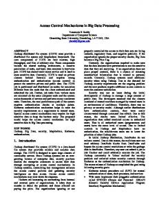
2 SIGNAL PROCESSING The wire/scraper signals are provided for DSPs through custom AFEs.[6] Each AFE is programmable given operator defined parameters. The data is the result of digitized, full-scale charge signals configurable by programming the AFE’s applied gain and integration. Signal polarity and wire/scraper potential is adjustable through programmable bias batteries located in series with each channel. (Figure 1)
1 INTRODUCTION Beam-Halo formation experiments are being conducted with the Low Energy Demonstration Accelerator (LEDA) [1]. Nine Wire Scanner / Halo Scraper (WSHS) stations were installed throughout a 52-magnet lattice to provide a means of acquiring beam core and beam halo data from which complete beam-halo profiles are constructed. [2] Each WSHS station consists of a horizontal (X) and vertical (Y) actuator assembly. Each actuator consists of one wire, used to measure the beam’s core, and two scrapers, used to measure the beam’s tail distribution. An integrated control system provides fully automated, realtime beam profile and tail distribution measurements as well as the capability for operators to manually acquire single wire or scraper data sets. This control system spans three computer platforms and integrates numerous program modules developed with various languages and software packages. Each platform and software tool/language was chosen and designed with the intent of satisfying control system requirements using the most applicable hardware and software available. WSHSs are accessed through DSP instrumentation mounted on custom mother-boards installed in a VXI
Figure 1: AFE control panel An AFE supplies two 12 bit channels and two 14 bit channels to both local DSPs. The DSPs contains two data buffers each. Channel-to-buffer configuration is within the software. Wire signals are connected to the 12 bit channels, scraper signals are connected to the 14 bit channels where more accuracy is needed. PVs process synchronously causing driver level software to notify the associated DSP to acquire data from the AFE. After the data has been acquired into the buffer, the DSP signals EPICS to upload the data.
3 INTER-PROCESS COMMUNICATION EPICS CA and CA extensions provide system-wide integration by creating TCP/IP connections between all necessary process modules. These modules access EPICS PVs using CA. Modules set/monitor/retrieve the PVs providing a communication means for process control. Specific PVs are implemented to contain commands, status, and signal data. Process control is tightly managed by a central SNL sequence using the PVs to send execution instructions to individual modules. Each support module monitors specific PV(s) and, when processed, the module proceeds according to the PV’s parameter(s). Any data needed is passed with PVs. Some processes return status or error codes to sequence through PVs.
4 CENTRAL PROCESS CONTROL The central process control sequence is responsible for completing both automatic scan/scrape measurements and manual wire/scraper data acquisition. It also handles errors, recovering from those within the EPICS system and notifying operators of unrecoverable remote errors. While the sequence configures most parameters for motor control and data processing, it relies on a remote LV virtual instruments to control actual motor movement and remote IDL routines to complete data processing. Operator control and feed-back occurs via the Wire/Scraper control screen (Figure 2).
and data processing. Upon completion, a transitional state processes the results and archives both the measurement results and the raw DSP data. The sequence configures the parameters for positioning the wire/scraper and acquiring data during measurements. The operator sets the measurement range for both scans and scrapes. For scans, the operator defines the number of steps. The sequence steps through scan then signals IDL to calculate the results. Based on these results, IDL calculates the safe insertion limits for the scrapers. For scrapes, the operator sets N, the number of scraper steps to take per single scanner step. Each scraper is required to visit the same spatial locations as the wire within the overlapping scan/scrape range; the N steps are averaged during the spatial integration, improving the fit. The sequence adjusts the scraper range according the wire scan positions and the scraper insertion limits. The sequence converts motor parameters into targeted encoder positions. It then compiles an instruction set within a waveform PV. Included is the WSHS station, the X or Y axis, and the. LV monitors this PV and when processed, LV interprets the parameters and completes the move as specified. The sequence holds its state until LV responds. The response contains the assembly station, axis, encoder and potentiometer read-back values, and the status, i.e., success or an error code, within a waveform PV. The sequence verifies these parameters and handles any errors accordingly. Assuming a successful move, the sequence grabs the next set of synchronous waveform data from the appropriate wire, scraper, and associated toroid waveform PVs. It verifies the appropriate data is valid beam pulse data by comparing the average of a specified range within the toroid data set to a given threshold. If the data is not valid, the sequence grabs new data sets and re-validates. This process may repeat up to a user-defined number of times. The final data sets are tagged if invalid and copied into unique waveform buffers for IDL. The sequence sets a binary PV to trigger a specific set of IDL routines to process and plot the data. This sequence continues this process for all steps in a measurement. At the end of each scan or scrape, the sequence sets another binary PV signaling IDL to write the raw data and processed results to disk for archiving.
3.2 Manual Data Acquisition Figure 2: Operator Control Screen for Scans and Scrapes
3.1 Automatic Scans and Scrapes The sequence processes as a state-machine, following execution paths according to the measurement’s state. There are separate states for X and Y scans, X positive and negative scrapes, Y positive and negative scrapes, and measurement transition. Each execution path accesses PVs unique to that state for holding data and process commands. The scan and scrape states follow the basic algorithm of parameter configuration, actuator movement,
Operators are given the capability of acquiring single data sets from an assembly’s wire, scraper, and the associated toroid with the motor in a specific position. This feature is used when testing the controls software, trouble shooting the hardware, or examining the signal of a particular area of the beam pulse. To acquire data from a specific location, the operator specifies the station, axis, and position, then activates an acquisition. The sequence translates the position into an encoder value and compiles the LV instruction set. LV moves the motor and sets the response. The sequence grabs the data sets and triggers an IDL process. IDL plots the waveforms of the three data sets.
The wire/scraper remains in the last manual location until the operator requests another acquisition or instructs the sequence to move the motor home.
4 MOTOR CONTROL Each assembly contains a stepper motor, stepper motor controller, linear encoder, linear potentiometer, and motor brake. The LV system interfaces with this hardware to achieve motor movement and status checking. [7] LV monitors the command PV set by the sequence and when processed, LV interprets the parameters into instructions including WSHS station, X or Y axis, and the targeted encoder position. LV verifies that all other motors are in home position, then signals the specified motor to move. LV will continue to signal the motor to move until the potentiometer read-back is within a given threshold or an error is detected. If the move is successful, LV turns off power to the motor, setting the brake and removing any motor drive noise. LV sets parameters in the response PV including the station, axis, final encoder reading, and final potentiometer reading of the assembly to which move was applied. If LV detects an error in actuator movement or experiences and error within the VI, it sets an error code in the response. The sequence monitors this PV, verifies the parameters and continues to process.
5 DATA PROCESSING AND DISPLAY The central control sequence copies acquired data from the active wire, scraper, and associated toroid into waveform buffers. It then sets a binary PV triggering a specific IDL program to execute. There are separate programs to process the acquired data from X and Y scans, X negative and positive scrapes, and Y negative and positive scrapes. For each step in a measurement, IDL stores relevant data in memory, normalizes the wire/scrape data to the associated toroid, and updates the real-time plot. After both X and Y scans complete, IDL corrects and plots any invalid data points and calculates and plots the Gaussian fit (Figure 3). IDL also calculates and displays the X and Y moments and the maximum error between requested and actual encoder positions. The results and the raw data sets are written to a text file for archiving. Using the scan data, IDL computes the relative position where the wire signal rises above background noise. It also calculates the safe insertion limits for each scraper using the scan’s calculated results. IDL presents these to the operators who then set parameters for the scrapes.
During scrapes, IDL normalizes the data sets and updates the logarithmic plots. (Figure 4) Figure 3: Wire Scan Profile
Figure 4: -Y and +Y Halo Scrape Distributions Joining the scraper and wire data is done off-line by an independent IDL application.[8] This application has the flexibility to read in and process the wire scan/ halo scrape data sets of choice.
5 REFERENCES [1] P.L. Colestock, et al., “The Beam Halo Experiment at the LEDA Facility: A First Test of the Core-Halo Model”, Proceedings of LINAC2000. [2] J. D. Gilpatrick, et al., “Beam-Profile Instrumentation for Beam-Halo Measurement: Overall Description and Operation”, this conference. [3] Licensed product of WindRiver, Alameda, CA. [4] Licensed product of National Instruments, Austin, TX. [5] Licensed product of Research Systems, Boulder, CO. [6] M. E. Gruchalla, et al., “Beam Profile WireScanner/Halo-Scraper Sensor Analog Interface Electronics”, this conference. [7] Dean Barr, et al., “Design and Experience with the WS/HS Assembly Movement Using LabVIEW VIs, National Instrument Motion Controllers, and Compumotor Electronic Drive Units and Motors”, this conference. [8] J. H. Kamperschroer, et al., “Analysis of Data from the LEDA Wire Scanner/Halo Scraper”, this conference.