In this paper, we investigate two approaches to sensor validation and fusion, the first ... Ã x = 0. However, in practice the velocity will undergo at least slight changes. ..... The performance of the algorithms is rated according to smoothness of ...
PROBABILISTIC AND FUZZY METHODS FOR SENSOR VALIDATION AND FUSION IN VEHICLE GUIDANCE: A COMPARISON Kai Goebel and Alice Agogino University of California at Berkeley and Satnam Alag General Electric CR&D, Schenectady USA Abstract This paper compares methods to deal with uncertainty associated with longitudinal distance sensors in an Intelligent Vehicle Highway Systems (IVHS) based on two approaches − probabilistic and fuzzy − for sensor validation and sensor fusion. The probabilistic approach uses Kalman Filter based techniques, with on-line adaptive learning of noise characteristics. The fuzzy approach uses non-symmetric validation regions in which sensors readings are assigned confidence values. Here, each sensor has its own dynamic validation curve which is shaped according to sensor characteristics, taking into account the range, external factors affecting the sensor, reliability of the sensor, etc. We investigate the performance of these methods as applied to follower vehicle guidance for platooning tasks in an IVHS in the presence of Gaussian and non-Gaussian noise. Introduction In the IVHS a string of closely spaced vehicles called platoons will travel under automatic control at high velocities. In order to perform its basic functions (such as longitudinal control, lateral control, platooning, maneuvering techniques, e.g. lane change, exiting the automated lane), the IVHS requires a large number of sensors for control at the coordination level, the engine level, and for sensing and communication between the vehicles and the IVHS main controller. The requirement of high data fidelity is often times thwarted by the uncertainty added to the measurements which stems from a variety of sources due to a lack of complete understanding of the principles governing the operation of the sensor and its physical and spatial limitation. More imprecision is added to the system due to an incomplete knowledge of the environment, due to sensor failure, the tolerances added during manufacturing, receptiveness to environmental conditions, etc. Redundant readings obtained from several sensors measuring the same quantity are never the same at some level of precision. This means necessarily that one sensor gives more precise information than the other ones. It is therefore necessary to identify how each sensor performs and to then use the information from all sensors to output one value for further processing, a process called sensor validatin and fusion. Sensor validation is the process by which the sensor data are authenticated through rating their integritiy. Sensor fusion is the process of integrating the information obtained from several sensors into one value. In this paper, we investigate two approaches to sensor validation and fusion, the first based on probability theory and the other based on fuzzy logic. The probabilistic approach models the system as a Markov process with a model for the state transition between two sample times. There is uncertainty associated with the state transition and the sensing model. This uncertainty is approximated by means of zero mean white Gaussian noise. The well known Kalman filter is an example of this algorithm where the state transition model, the process and sensor noise 1
characteristics are assumed to be known. The performance of the algorithms will deteriorate when there is any change in the process model and/or changes in the noise characteristics. In this case, one can use an adaptive estimation algorithm where the model and noise characteristics are estimated on-line. For fuzzy sensor fusion, a confidence is found for a given measurement based upon the expected value, the system state, the environmental conditions, sensor reliability, and physical limitations of the system. Where possible, values obtained through functional redundancy are integrated into the fusion process. These values rely on sensor readings which do not directly measure the quantity of interest but are calculated using other measured system variables which stand in some functional relation to the variable of interest. The advantage of exploiting this information is an increase in robustness against sensor failure resulting in better performance of the controller. In the next section we explain the probabilistic approach for sensor validation and fusion. This is followed by the fuzzy approach. Then we compare the two approaches by carrying out detailed Monte Carlo simulations. Probabilistic Sensor Validation and Fusion Depending on their position on the automated highway, vehicles can be divided into two types: those in the platoon which are called follower vehicles and those that lead the platoon which are called leader vehicles. Those that travel alone are equivalent to a platoon of length one. The tracking tasks for these two vehicle states are different. It is therefore necessary to distinguish between these two cases in our validation and fusion methodology. To deal with the various situations, we further divide the operating conditions into several states (see Fig. 1) (Alag et al., 1995). There are three states for the follower vehicles: steady state, transient, and hazardous states. The first two are desired states while the third is undesired. A vehicle under automatic control is defined to be in the steady state when it is in a platoon and is trying to follow the one before it at a fixed known distance. Whenever the vehicle carries out a maneuver such as a split (leave the platoon), merge (join the platoon), or lane change it is defined to be in a transient state. This state involves relative acceleration between the vehicles and includes the state of the lead vehicle in the platoon. The last state, the hazardous state, is defined as the state when the vehicle carries out emergency maneuvers to avoid an accident. The lead vehicle, on the other hand, has only two states: a desired state and a hazardous state. If the lead vehicle’s distance to the next object is large enough (e.g., the distance to the next object is greater than the minimum for safe distance or the object is out of range), then the state is a desired state. If the distance to the next object is too small, we say it is a hazardous state. Other hazardous states exist beyond the one outlined above (Hitchcock 1993). Automat ed Vehicle
Types
States
Leader
Follower
Desire d
Undesired
Nothing in
P latoon
Range
Fol lowing
Transition
Hazardous
Desired
Steady
Undes ired
Transient
Hazardous
Fig. 1: Classification of states for the automated vehicle The probabilistic approach models the system as a Markov process with a state transition model to predict the state of the system at the next sampling time using the current state of the system. Based on the above discussion three state evolution models can be used for this process: 1.) a one-state 2
nearly constant distance; 2.) a two-state nearly constant velocity, and 3.) a three-state nearly constant acceleration. We briefly explain the one state nearly constant distance model. For details on the other models refer to Alag et al. (1995). One State Nearly Constant Distance Model The one state nearly constant distance model is appropriate for the case when the vehicle is in the steady state. Steady state is defined as the state in which the automated vehicle in a platoon follows the one before it at a constant (zero) relative velocity, i.e. at xÝ= 0 . However, in practice the velocity will undergo at least slight changes. These changes are modeled as a continuous time white noise ˜ν as follows, xÝ(t) = ν˜ (t) E[ν˜ ( t )]= 0 E[ν˜ (t )ν˜ ( τ )]= q(t )δ (t − τ ) where E[ν˜ ( t )] is the expected value of ν˜ (t) q(t) is the covariance of ν˜ (t) . The discrete time state equation is a Wiener process, i.e., a process driven by white noise x(k + 1) = x(k) + v(k) Τ Q = E[v(k)v (k )] where Q is the covariance of v(k). This one state Wiener model can also be used during the maneuvers. There are two parameters: the process noise covariance and the sensor noise covariance which need to be specified. These two parameters affect the overall performance of the algorithm, as their relative magnitude is used for generating the validation region and the relative weighting of the state evolution model with the incoming evidence. The Kalman filter is the optimal estimation filter when all its assumptions are satisfied − known state evolution model, process and sensor noise characteristics. As shown in Alag (1996) nearly perfect tracking can be obtained when all the noise characteristics are known. The tracking performance is a function of how closely the modeled parameters are to their actual values. A sudden change in the operating conditions, deterioration of the sensor, changes in the vehicle dynamics, etc. may change the characteristics of the process and sensor noise. These noise characteristics can be estimated on-line using adaptive estimation algorithms. Alag (1996) presents a graphical framework for developing adaptive probabilistic algorithms. The computationally least expensive adaptive estimation process uses the Multiple Discrete nodes Algorithm (MDA) for either the process or sensor noise. More computationally expensive Bayesian algorithms can in most cases distinguish between sensor and process noise, which the MDA cannot. This however is not a major constraint for the platooning follower case, where the deviation in the process (process noise) is negligible, due to which one can assume the process noise to be more or less constant and estimate the changes in sensor performance. Alternatively, in the case when there is a change in the process (emergency or maneuvering) the sensor noise covariance (assumption: sensor is not deteriorating during this instant) can be assumed to be more or less constant. Of course both sensor and process noise can be estimated together, but this is more computationally expensive than just estimating sensor or process noise. Fig. 2 shows the the graphical representation for the algorithm using vector dynamic belief networks (VDBN) for the multiple model algorithm and for the algorithm to obtain feedback on the process noise. For the multiple model algorithm, the multiple models correspond to a different hypothesis in process noise, while all other parameters of the multiple models for this implementation were similar. 3
Continuous C ontinuous
Con tinuous
z1(k)
Continuous
z1(k )
z1(k +1)
z1(k+1)
Changing
Changing
Continuous
Changing
x(k) x(k)
x(k +1)
x(k+1) Continuous
Continuous
Q(k)
M(k+1)
M (k) Discrete
Discrete
Q(k+1)
Discre te
Fig. 2: VDBNs corresponding to the multiple model algorithm and for process noise estimation The multiple model algorithm (generalized pseudo-Bayesian of first order) in this case simplifies to: Prediction ∆ Pr (M (k + 1) = j k )= m j (k + 1k ) = ∑ Pr(M (k + 1) = j M (k ) = i )Pr(M (k ) = i k )
[
]
i
m j (k + 1k ) = m1 (k k ),⋅⋅, mn m (k k ) ⋅ Φ m (k ) xˆ j (k + 1 k ) = F xˆ (k k )
Pj (k + 1k ) = FP (k k )F T + Qj
xˆ (k + 1k ) = Fxˆ(k k )
P(k + 1 k ) = FP (k k )F T + ∑ m j (k + 1 k )Qi j
Validation Pr (z(k + 1) k ) = N (z(k + 1); S(k + 1), zˆ(k + 1k ))
)
(
= N z ( k + 1);H (k + 1)P(k + 1 k )H( k + 1) T + R (k + 1), H (k + 1) xˆ(k + 1k )
ν(k + 1) = z(k + 1) − zˆ(k + 1k ) .
Accept the reading if ν T (k + 1)S −1 (k + 1)ν (k + 1) ≤ γ Estimation Pr (z(k + 1) k, M (k + 1) = j ) = N z (k + 1);S j ( k + 1), zˆ(k + 1k, M(k + 1) = j )
(
(
)
= N z ( k + 1);H (k + 1)Pj (k + 1 k )H (k + 1) + R(k + 1), H( k + 1) xˆ (k + 1 k ) T
node M( k + 1) Π(M (k + 1)) = m1 (k + 1 k ),⋅⋅,mn m (k + 1 k )
[
[
λ (M (k + 1)) = π1M ,⋅⋅,π M
[
nm
]
] .
Bel(M( k + 1)) = α m1 (k + 1 k )π 1M ,⋅⋅,mn m (k + 1k )π Mn
m
Hence,
]
π iM mi (k + 1 k ) . Bel(m(k + 1k + 1) = i ) = mi (k + 1k + 1) = ∑ π Mj m j (k + 1k ) j
4
)
z(k+1)
z(k )
Continuous
Continuou s
x(k)
x(k+1) R(k)
R( k+1) Discrete
Discrete
Fig. 3: VDBN for sensor noise feedback Fig. 3 shows the VDBN for sensor noise feedback. Extensive testing of various adaptive algorithms was carried out in Alag (1996). Here, the mean of the prior probabilities over a sliding window was taken as the a priori probabilities. As a variant to that approach we investigated an alternative approach where the estimates for the noise characteristics were updated after a number of samples. An update of this kind however leads to non-uniform computational load. Fig. 4 shows the sum squared error when three clusters were used to obtain feedback on sensor noise. The three curves correspond to three ranges that the clusters modeled. The dash-dotted line corresponds to the hypothesis being at [0.01 0.1 1.25], the dashed line corresponds to a smaller range [0.05 .15 1], and dotted line corresponds to the smallest range corresponding to [0.1 0.15 0.2]. As can be seen the sum squared error is a function of the number of samples, after which feedback was used to update the estimates, and the distance between the cluster centers. This EPS image does not contain a screen preview. It will print correctly to a PostScript printer. File Name : fig6_15_l.ps Title : MATLAB graph Creator : MATLAB, The Mathworks, Inc. CreationDate : 03/08/96 21:36:38 Pages : 1
Fig. 4: Sum squared error using three different cluster centers to obtain feedback on the sensor noise We investigated updating after a number of samples rather than taking a moving window average. Fig. 5 shows the sum of the squared error of the multiple model algorithm (dashed line), the algorithms in using λ message considering both the mean (dotted line) and distribution (dasheddotted line) to estimate the process noise. Here, three Gaussian clusters were used to represent the standard deviation of the process noise of q=[0.005, .025, 0.05]. Note that the three hypotheses represented by this discrete node correspond to a very large range of possible process noise. The sum squared error is plotted versus the number of samples after which the probabilities were updated, i.e., after which feedback on the process noise was obtained. For this simulation case, all three algorithms seemed to perform equally well, which is not surprising because sensor noise was assumed to be constant.
5
This EPS image does not contain a screen preview. It will print correctly to a PostScript printer. File Name : fig6_16_l.ps Title : MATLAB graph Creator : MATLAB, The Mathworks, Inc. CreationDate : 03/08/96 21:41:57 Pages : 1
Fig. 5: SSE for the simulation using a three state discrete node to estimate the process noise Fuzzy Sensor Validation and Fusion An algorithm for fuzzy sensor validation and fusion (FUSVAF) is described. This algorithm makes use of a Fuzzy Exponential Weighted Moving Average (FEWMA) time series predictor, dynamic validation curves which are determined by sensor characteristics, and a fusion scheme which uses confidence values for the measurements, the predicted value, the measurements, and the system state (Goebel and Agogino, 1996, Goebel, 1996). Inputs to the FUSVAF algorithm include the raw sensors measurements. The output is the corrected value which can be used for the machine level controller as well as for supervisory control tasks (Agogino, et al., 1995). Additional information regarding the performance of individual sensors or actuators can be provided for use in a diagnostic module. The validation and fusion algorithm works in the following manner: incoming sensor readings are validated using the validation gate and the old fused value. This fused value is then used to assess the state of the system expressed by a. It is also employed for prediction which in turn is necessary to perform the validation of the next time step. The fused value is utilized at the machine level controller and for supervisory control tasks. The algorithm is displayed in Fig. 6 −1 where z denotes an unit delay. z-1
z -1 z -1
calculate new predicted value
raw sensor readings
determine confidence values for sensor readings
z -1 calculate new α
fuse sensor readings
fused value for machine level controller/ supervisory controller
Fig. 6: Algorithm for fuzzy sensor validation and fusion We begin by explaining how to obtain the confidence values which are assigned to all sensor measurements. This confidence value depends on the specific sensor characteristics, the predicted value, and the physical limitations of the sensor value. The assignment takes place in a validation 6
gate which is bounded by the physically possible changes of the system it can undergo in one time step. This is an application of the ASV (Kim et al., 1992) which proposes limit checking for new sensor values. Due to the inertia of the system, it can only change within certain physical limits. If the sensor reading shows a change beyond that limit, it cannot be a correct value. In the context of validation gates, these limits are the boundaries for the validation gate. Sensor readings outside the validation gate are assigned a confidence value of 0 since they do not make sense. Within the region, a maximum value of 1 will be assigned to readings which coincide with the predicted value. The curve between the maximum and the two minima is dependent on the sensor behavior. Generally, this is a non-symmetric curve which is wider around the maximum value if the sensor is known to have little variance and narrower if the sensor exhibits noisy behavior. The curves change dynamically with the operating conditions which allows to capture the change in behavior of the sensor over its operating span. Other effects resulting in changing sensor performance can be integrated into the validation curves as well. If, for example, environmental conditions, such as a change in temperature or humidity, are known to affect the sensor, the information can be easily integrated either in a crisp manner or through a fuzzy logic rule based approach utilizing information about the external effects. One such rule could for example be IF humidity large THEN use narrow base for validation curve for sensor X. The resulting assignment for confidence values is
0 2 ˆx − v 2 left − xaˆ −z − left a left e − e xˆ −v 2 left − 1− e a left σ = ˆx −z 2 xˆ − v 2 right − − e a right − e a right ˆx − v 2 right − a right 1− e 0
z < v left vleft < z ≤ xˆ
xˆ < z ≤ vright z > v right
where s is the confidence value for a particular sensor v right and v left are the right and left validation gate borders, respectively a right and a left are the parameters for the left and right validation curve z is the sensor reading xˆ is the predicted value. A validation gate is shown in Fig. 7.
sensor confidence
σ2 σ3 σ1
z2 z3 x(k-1) xˆ (k )
z1
max. possible pos. change
max. possible neg. change
fuzzy validation gate
7
measurement
zi si xˆ ( k )
sensor measurements sensor confidence values
predicted value x(k-1) old value at previous time step Fig. 7 Validation gate for the assignment of confidence values The fusion is performed through a weighted average of confidence values and measurements plus a term which includes the predicted value weighted by a and a constant scaling factor w. The sum of the confidence values times the measurements rewards measurements closest to the predicted value the most, depending on the validation curve which expresses a trust in the operation of each sensor through the design of its shape. Measurements further away are discounted. The confidence value drops to 0 at the border of the validation so that measurements beyond the gate borders are not taken into account. The term including the predicted value permits the calculation of fused values even when all sensors have values outside the validation region. Furthermore, it includes information about the state of the system through the use of the adaptive parameter a. If the system is in a steady state, a is large and past history should be integrated more. When the system is in a transient state, however, a is small and the predicted value has less weight thus reducing lag induced by the term. The calculation of a will be explained with the FEWMA algorithm later. Parameter w is a scaling factor which has to be tuned to the system at hand. Since a will be used in calculating the predicted value without the use of w, the two parameters are not integrated into one value. The fusion algorithm is n α xˆ ∑ z iσ (z i ) + ω xˆ f = i =1n α ∑ σ(z i ) + ω i =1 where xˆ f : fused value zi: measurements s: confidence values a: adaptive parameter representing the system state w: constant scaling factor xˆ : expected value. Note that if all sensors lie on one side of the predicted value, the fused value will also be pulled to the same side. This ensures that evidence from the sensors is closely followed yet discounted the further it gets away from the predicted value. The sensor model for the sonar sensor was experimentally established to be x + r Gσ s for x < 4 8-x x + r σ for 4 ≤ x < 8 and r u ≤ G s 4 s(x) = 8- x for 4 ≤ x < 8 and r u > 15 4 15 for x ≥ 8 where s(x) is the modeled sonar measurement given the true distance x r G is a random number with Gaussian distribution r u is a random number with uniform distribution σ s is the variance for the sonar sensor. The sensor model for the radar sensor is 8
x + r G (σ r + σ d ) +ρ for x < 3.8 11x − 38 + rG (σ r + σ d ) + ρ for 3.8 ≤ x < 3.95 20.27 - 3.714x + r (σ + σ ) + ρ for 3.95 < x < 4.3 G r d r (x ) = x + r G (σ r + σ d ) +ρ for 4.3 ≤ x < 8.5 6.67x − 48.167 + rG (σ r + σ d ) + ρ for 8. 5 ≤ x < 8.8 31.62 − 2.4x + rG (σ r + σ d ) + ρ for 8.8 ≤ x < 9.3 x + r (σ + σ ) +ρ for x ≥ 9.3 G r d where r(x) is the modeled sonar measurement given the true distance x σ r is the variance for the radar sensor σ d is the distance related variance 0.1 for r G > 2 ρ = −0.1 for r G < −2 0 elsewhere ρ is a non-Gaussian spike of small order described by Comparative Simulations The following graphs show the results for a series of experiments covering different types of noise and failures including random Gaussian noise, random bias, clutter, outliers, and steady bias. The MDA and fuzzy fusion was compared to a Kalman filter using probabilistic validation gates. The MDA also learns the covariance of the noise for each sensor and adapts its covariance matrices accordingly. It is shown how both perfect and false information about the system affect the performance of the algorithms. The parameters of the fuzzy system were learned through machine learning techniques using genetic algorithms (Agogino et al., 1997) where training data had conditions similar to the test data. Two types of system behavior were investigated. First, a random walk was considered. Here the system can randomly jump from one point to the next within certain limits. Monte Carlo simulations of 100 runs over 100 steps each were carried out and compared. The second system under consideration was an inertia driven system which has more restriction on the behavior of the system. That is, it does not allow sudden jumps from one state to the other. Rather, smooth transitions are required between the states. The experiments were carried out in a systematic manner, varying the modeled and perceived system noise covariances, the modeled and received sensor noise covariances, the presence and absence of validation gates, variance and magnitude of clutter, presence and magnitude of randomized bias, magnitude of steady bias, and the presence of outliers which resulted in 64 condition permutations. Details on the design of the experiments can be found in Goebel (1996). The results of the two experiment types are summarized in Figs. 8 and 9. In the first set of experiments, a Monte Carlo simulation was performed for a random walk. 100 experiments each lasting 100 steps were carried out for each of the 64 conditions. Cases 1-2 investigate the case of little Gaussian noise with either perfect or imperfect information about system and noise variance for the probabilistic system. Cases 3-4 add validation gates to the MDA and the Kalman filter. In cases 5-8, clutter was added while the first four conditions were repeated. Cases 9-16 add a small random bias, cases 17-32 add a steady bias, and for cases 33-64, outliers were added to the sensor readings. Each algorithm performs well under certain circumstances. The Kalman filter performs best in the presence of Gaussian noise alone as well as when the perfect or near perfect information about system and sensors is available. It performs very poorly without validation gate in the presence of nonGaussian noise. The MDA works best in the presence of clutter and in the presence of outliers when no steady bias is present. In the presence of a bias, the MDA does not perform very well, although it does not exhibit the high mean error of the Kalman Filter. This behavior is to be expected since both the algorithms assume that the sensor signal does not have a bias. The fuzzy algorithm works 9
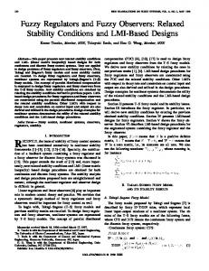
best where the system and sensor behavior is not well known regardless of the conditions. It does not seem to be affected by any noise condition but stays at the same mean error for all cases. The second set of experiments (Fig. 9) involved a similar scenario except that the random walk was replaced by an inertia driven system response taking into account the real behavior of many systems which cannot arbitrarily move from one state to another. Again 100 experiments each lasting 100 steps were performed for each of the 64 conditions. The results are somewhat different than the random walk experiments although the same parameters were used. Each algorithm shows weaknesses and strengths.. However, where the Kalman filter and the MDA are optimal, the fuzzy filter performs a little worse. The differences are not large, though, and the fuzzy filter performs better in certain scenarios than both of the probabilistic algorithms when system and sensors models are different than reality. The fuzzy algorithm does not do as well as the random walk experiments in the presence of clutter, probably because when the system is dynamically shifting, the parameters are very receptive to readings changes. 7 FUSVAF MDA . . . . . . Kalman Filter
6 5 4
3 mean error 2 1 0
0
10
20
30
40
50
60
experiment batch no. Fig. 8: Results of Monte Carlo runs for a random walk; comparison of fuzzy and probabilistic algorithms
10
2.5 FUSVAF MDA . . . . . . Kalman Filter
2 1.5
mean1 error 0.5 0
0
10
20
30
40
50
60
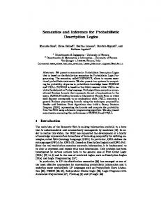
experiment batch no. Fig. 9: Monte Carlo runs of fuzzy and probabilistic algorithms for inertia driven system The detailed results can be found in Goebel (1996). As an example of the output, consider Fig. 10. On the left side of the graph the mean error for 100 experiments are displayed. Each experiment is 100 steps long. The right side shows an example for how the algorithms behave. Only the Kalman filter (dotted line) and the fuzzy algorithm (solid line) are shown. For this case only Gaussian noise was considered. The mean error for both algorithms is quite small with the Kalman filter performing better. Case 1 does not provide perfect information about the sensor noise while Case 2 does. Cases 3 and 4 have the same pattern as Cases 1 and 2 but also use a validation region. The fuzzy algorithm is not affected by these changes as it does not access this type of information. With a validation gate, performance of the probabilistic algorithm actually degrades with some peaks recording worse than the fuzzy algorithm. This is due to the fact that the validation region for the probabilistic algorithm is kept at three times the variance which may not be the actual variance. Therefore, some readings are recorded as outliers while they are not really outliers. The algorithm then uses information only from previous readings and extrapolates from these which leads to poor performance. error for case 1 example for case 1 0.3 115 0.2 110 data
error 0.1 0
0
50
100
105
0
experiment
10
step
error for case 2
0.4
5
example for case 2
108 107
0.2 error 0
data 106 0
50
100
experiment
105
0
5 step
11
10
error for case 3
0.4
example for case 3
108 106
0.2 error 0
data 104 0
50
100
102
0
experiment
10
step
error for case 4
0.4
5
example for case 4
110 105
0.2 error 0
data 100 0
50
100
experiment
95
0
5
10
step
Fig. 10: Results of Monte Carlo runs, cases 1-4 Conclusions and Summary The probabilistic algorithm is based on the theoretically sound concept of probability theory.. They model the process as a Markov process with added uncertainty in the process and sensor noise. They perform well when the modeled characteristics are close to realty. MDA based adaptive probabilistic algorithms perform well in the presence of Gaussian noise alone and is robust in the presence of clutter. Another advantage is the ability to learn the noise covariances over time when the system covariance is steady. The FUSVAF algorithm for sensor validation and fusion provides a tool which can deal with Gaussian and non-Gaussian noise because the sensor characteristics can easily be modeled according to their characteristics. The parameters are tuned off-line using machine learning techniques. They thus requires more customization for each specific application than parameters of the probabilistic algorithm. Although the fuzzy filter by definition is a nonoptimal filter, it rejects Gaussian noise considerably well. Its real strength, however, lies in handling unknown system noise and non-Gaussian noise. The performance of the algorithms is rated according to smoothness of returned fused value, error spacing of the simulation tool, robustness in the presence of non-Gaussian noise and sensor failure, and computational expense. In the presence of Gaussian noise alone, the probabilistic algorithm performs slightly better than the fuzzy approach. It also performs better in a series of non-Gaussian noise situations. The algorithms benefits from the ability to learn noise covariances over time. The fuzzy approach performs better when the system covariance is not known and in certain situations of non-Gaussian noise, in particular steady bias noise. This is due in part to the additional information which can be included in the shape of the validation regions. However, no algorithm is absolutely fool proof. There exist conditions at which every algorithm can be thrown off such as improper settings of the parameters or lack of proper sensor measurements. The latter problems can be alleviated through the use of sensors which use different techniques and physical configurations. Other sensors which do not use the same principle should be integrated to provide a suite of sensors which operate independently from each other and provide the maximum amount of safety. Such sensors could use GPS information, but even sensors which are already on-board (such as a tachometer together with the information about gear ratio or accelerometers) are useful for this purpose. The integration of quantitative information from vision sensors is a straightforward extension. Thus the use of fusion algorithms can lead to an improvement in both comfort and safety in IVHS. 12
If knowledge about sensor behavior exists, i.e., if regions or environmental conditions are known where the sensor acts in a Gaussian fashion, and the system is in a steady state, the MDA should be chosen. If, on the other hand, the conditions change unpredictably or the noise is known to be of non-Gaussian nature, the FUSVAF algorithm should be used since it performs more robustly over a wide range of non-Gaussian as well as Gaussian noise. An improved scheme would include both algorithms for an hybrid approach which draws from the strengths of each method. Each filter has to be tuned to perform in an optimal way. Ideally, sensor data exist to allow tuning for the parameters. If such data do not exist, a choice of the parameters should be used as outlined earlier in this section. The strength of the FUSVAF algorithm is its ability to incorporate knowledge about sensor characteristics and external conditions through the use of appropriate validation curves. These curves can be updated dynamically. Computationally, the FUSVAF algorithm is a less expensive validation and fusion procedure than the MDA. References Agogino, A., Goebel, K., and Alag, S., “Intelligent Sensor Validation and Fusion for Vehicle Guidance Using Probabilistic and Fuzzy Methods", MOU157, Final Report, California PATH Research Report, to appear, 1997. Agogino, A., Goebel, K., and Alag, S., “Intelligent Sensor Validation and Sensor Fusion for Reliability and Safety Enhancement in Vehicle Control", MOU132, Final Report, UCB-ITSPRR-95-40, California PATH Research Report, 1995. Agogino, A., Alag, S., Goebel, K., “A Framework for Intelligent Sensor Validation, Sensor Fusion, and Supervisory Control of Automated Vehicles in IVHS", Proceedings of the ITS America Annual Meeting, Washington, D.C., 1995. Alag, S., A Bayesian Decision-Theoretic Framework for Real-Time Monitoring and Diagnosis of Complex Systems: Theory and Application, Ph.D. Thesis, Department of Mechanical Engineering, University of California at Berkeley, Berkeley, 1996. Alag, S., Goebel, K., and Agogino, A., "Intelligent Sensor Validation and Fusion used in Tracking and Avoidance of Objects for Automated Vehicles", Proceedings of the ACC 1995, Seattle, 1995. Goebel, K., and Agogino, A., "An Architecture for Fuzzy Sensor Validation and Fusion for Vehicle Following in Automated Highways", Proceedings of the 29th ISATA, Florence, Italy, 1996. Goebel, K., Management of Uncertainty for Sensor Validation, Sensor Fusion, and Diagnosis Using Soft Computing Techniques, Ph.D. Thesis, University of California at Berkeley, Berkeley, 1996. Goldberg, D.E., Genetic Algorithms in Search, Optimization, and Machine Learning, Addison Wesley, Reading, MA, 1989. Hitchcock, A. 1993. Intelligent Vehicle/Highway System Safety: Specification and Hazard Analysis. Transportation Research Board No.930435. Khedkar, P., and Keshav, S., “Fuzzy Prediction of Time Series”, Proceedings of the IEEE International Conference on Fuzzy Systems, San Diego, CA, USA, 8-12 March 1992. Kim, Y.J., W.H. Wood, and A.M. Agogino, “Signal Validation for Expert System Development,” Proceedings of the 2nd International Forum on Expert Systems and Computer Simulations in Energy Engineering, March 17-20, 1992 (Erlangen, Germany), pp. 9-5-1 to 9-5-6.
13