May 1, 2013 - the dynamic model of the squirrel-cage induction motor taking account the broken rotor bars. The RMS values of the discrete wavelet transform ...
Asian Transactions on Engineering (ATE ISSN: 2221-4267) Volume 03 Issue 02
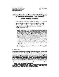
Broken Bar Fault Detection Based on the Discrete Wavelet Transform and Artificial Neural Network Dr. Mustafa M. Ibrahim, Habeeb J. Nekad Electrical Engineering Department- College of Engineering University of Basrah, Basrah-Iraq Abstract-- In this paper, we present an effective method to
In this paper, a simple and effective method is presented to detect the broken rotor bars based on the discrete wavelet transform (DWT) of the q-component of the stator current. The fault detection method is implemented by means of an ANN that is trained using the RMS values of the wavelet coefficients and the slip of the induction motor.
detect broken rotor bars fault in the induction motors. This method is based on the analysis of the q-component of the stator current and discrete wavelet transform (DWT). Using the dynamic model of the squirrel-cage induction motor taking account the broken rotor bars. The RMS values of the discrete wavelet transform coefficients are fed to the artificial neural network (ANN) to identify the machine state. The broken rotor bar fault detection algorithm is implemented using matlab/simulink. Index Term-- Induction motor, broken bar fault, DWT, ANN.
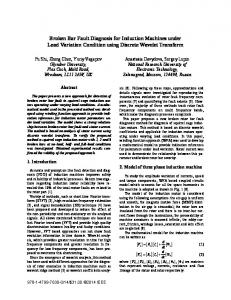
II. MODELING OF INDUCTION M OTOR The model of the induction motor is derived by using d and q variables in a synchronously rotating reference frame. A simulation model for the three-phase induction motor has been derived based on the mathematical model using matlab/simulink. The simulink model implemented in this paper is shown in Fig.(1). It consists of conversion blocks and motor dq-model as follows:A. abc-dq conversion To convert 3-phase voltage to voltages in the 2-phase synchronously rotating frame, they are first converted to 2-phase stationary frame (,) and then from the stationary frame to the synchronously (dq) rotating frame. The transformation is given by the following equations [5,6]:
I. INTRODUCTION Nowadays, fault detection and diagnosis of electrical machines become important issues in the field of the preventive maintenance of electrical machines. Induction motor is the most widely used in industry, mainly due to its low cost, reasonably small size, ruggedness, and slight maintenance. Although induction motors are reliable, they are subjected to some undesirable stresses leading to catastrophic faults and the interruption of the production [1]. In general, condition-monitoring schemes have been widely used to sense specific failure modes in one of three main induction motor components: stator, rotor, and bearings [2]. The current monitoring based techniques can be used to detect the faults of a squirrel cage induction machine: rotor bar faults, shorted winding fault, air-gap eccentricity faults, bearing faults, load faults, etc [3]. Among existing methods in induction motor condition monitoring, motor current signal analysis (MCSA) is the most commonly used technique [4]. Va
a
Vb
b
Vc
c
Supply
alfa
beta
abc-alfabeta
V alfa
√
[
]
[
√
]
]
[
][
]
Wr
V qs Vqs
alfabeta-dq
Rr
Rr
TL
TL
-C-
Te
ids
Scope
ids
ialfa
ialfa
w ibeta
iqs
wt
IM model
wt
ia ib
iqs
w -K-
√
]
[
V ds
Vds
V beta wt
[
ibeta
ic
Scope2
alfabeta-abc
dq-alfabeta
Clock Fig. 1. Induction motor simulation model
May 2013
ATE-40309027©Asian-Transactions
1
Asian Transactions on Engineering (ATE ISSN: 2221-4267) Volume 03 Issue 02
B. Motor dq-Model The dq-model of induction motor is represented according to the following equations: ( ⁄ )
In the present work, DWT uses q-axis current (iqs) so as to identify the broken bar fault. Daubechies-44 wavelet (db44) has been used as a mother wavelet. The supply frequency in this paper is taken to be 50 Hz and table I shows the frequency level of the wavelet coefficients.
( ⁄ ) (
T ABLE I
) (
Level
Frequency
Band
with
fS=5000
samples/sec
)
C. dq-abc Conversion This conversion does the opposite of the abc-dq conversion for the current variables. III. BROKEN B ARS F AULT D IAGNOSIS Under abnormal operating conditions related to the asymmetry caused by the broken rotor bars fault, sequence of additional sidebands components appear around the fundamental supply frequency at frequency fbr given by [7,8]: Where k=1,2,3,… These classical twice slip frequency sidebands components are the characteristics harmonics that have been widely used to diagnose the broken bars fault [9]. In the case where Nbb rotor bars are broken, the number of healthy bars is decreased to . Then, we obtain the simulink faulty model of the induction motor with the expression of the rotor resistance in faulty case as
III. DISCRETE W AVELET TRANSFORM (DWT) DWT actually splits a signal to several band-limited signals, the sum of which is equal to the original one. In this way, the original signal can be reconstructed as a sum of n detail signals ( ) and an approximation signal (An). Each detail Dj includes frequency components [ ], while the approximation signal includes all the lower frequency components, including the dominant DC signal. More specifically, at each level of DWT decomposition, low-pass (g[n]) and high-pass (h[n]) filters are applied, as shown in Fig. (2) [10].
D1
1250-2500 Hz
D2
625-1250 Hz
D3
312.5-625 Hz
D4
156.25-312.5 Hz
D5
78.12-156.25 Hz
D6
39.06-78.12 Hz
A6
0-39.06 HZ
IV. NEURAL NETWORK S TRUCTURE A neural network is a mapping which uses a dense interconnection of elementals artificial neurons [11]. ANN comprises connected elements (neurons) working similar to human nervous systems [12]. The network consists of inputs, which are multiplied by weights and then computed by a mathematical function f which determines the activation of the neuron. In ANN, two layers of neuron communicate via a weight connection network. The type of weighted connections used in this network is the feed-forward neural network, which composed by: (an input layer, one or more hidden layers, and an output layer) [13]. The mathematical model of neuron is presented by: (∑
)
In this work, the structure of the neural network consists of an input layer that is fed by eight inputs (the RMS values of the wavelet coefficients (A6, D6, D5, D4, D3, D2, and D1) and the slip of the induction motor), an output layer and two hidden layers.
Fig. 2. DWT decomposition
May 2013
ATE-40309027©Asian-Transactions
2
Asian Transactions on Engineering (ATE ISSN: 2221-4267) Volume 03 Issue 02
The RMS value of the discrete signal S can be determined by √( ∑
machine the RMS value of A6 is equal to 9.4422 while for one broken bar is equal to 9.1722. Fig. 6. reveals the difference in the wavelet coefficient (A6) between the different studied cases. The variation in the RMS values of the wavelet coefficients (A6, D6) for different conditions is given in table II.
)
The neural network model is trained by using Levenberg-Marquardt algorithm. The network has four outputs which is given by: Y=0 healthy system Y=1 one broken bar fault Y=2 two broken bars fault Y=3 three broken bar fault
T ABLE II
Case
V. SIMULATION RESULTS The motor used in the simulation study is 1.1 KW, 220V, 50Hz (see appendix), 2-pole induction motor, with a rotor with 16 bars. Fig. 3. shows the speed of the induction motor for healthy system and broken bars faults (one broken bar, two broken bars, and three broken bars) with full load. To detect the broken bars fault, with full load (S=0.066), we use the wavelet coefficients (A6, D6 - D1) of the q-component of the stator current. Fig. 4. shows the wavelet coefficients signals resulting from the wavelet decomposition of the stator q-axis current (iqs) of the healthy system with frequency band of theses coefficients and their RMS values while Fig. 5. shows the wavelet signals for one broken bar. The comparison between Fig. 4. and Fig. 5. shows clearly that the fault can be identified by means of the RMS values of the wavelet coefficients. For healthy
RMS values A6
D6
Healthy
9.4422
0.68717
One broken bar
9.1722
0.63652
Two broken bars
8.9256
0.58201
Three broken bars
8.6974
0.52042
The RMS values of the wavelet coefficients for level 6 and the slip of the induction motor are then be used as the inputs of the neural network to give an output which identifies the machine case. Fig. 7. shows the result of training during test while table III shows the output of the neural network for different condition of operation. The training performance gives low training mean square error (MSE) which is reached (7.32e-15) after 664 epoches.
T ABLE III
Case
Inputs of the ANN
Output
A6
D6
D5
D4
D3
D2
D1
RMS
RMS
RMS
RMS
RMS
RMS
RMS
No load
8.3829
0.7211
1.2791
1.1529
0.1310
0.0529
0.0168
0
0 healthy
Full load
9.4422
0.6872
1.2452
1.2101
0.2215
0.0434
0.0206
0.0662
0 healthy
No load
8.1432
0.6688
1.2450
1.1455
0.1184
0.0514
0.0164
0.0001
1 one broken bar
Full load
9.1722
0.6365
1.1958
1.1992
0.2085
0.0419
0.0207
0.0755
1 one broken bar
No load
7.9184
0.6093
1.2065
1.1376
0.1069
0.0498
0.0161
0.0003
2 two broken bars
Full load
8.9256
0.5820
1.1576
1.1894
0.1918
0.0403
0.0212
0.0872
2 two broken bars
No load
7.7028
0.5455
1.1711
1.1269
0.0937
0.0478
0.0156
0.0008
3 three broken bars
Full load
8.6974
0.5204
1.1238
1.1748
0.1636
0.0362
0.0213
0.1022
3 three broken bars
May 2013
ATE-40309027©Asian-Transactions
slip
3
Asian Transactions on Engineering (ATE ISSN: 2221-4267) Volume 03 Issue 02
Fig. 3. Speed of induction motor for different conditions
Fig. 4. Wavelet analysis of q-axis current for healthy machine
May 2013
ATE-40309027©Asian-Transactions
4
Asian Transactions on Engineering (ATE ISSN: 2221-4267) Volume 03 Issue 02
Fig. 5. Wavelet analysis of q-axis current for one broken bar
Fig. 6. Wavelet analysis of q-axis current for one broken bar
May 2013
ATE-40309027©Asian-Transactions
5
Asian Transactions on Engineering (ATE ISSN: 2221-4267) Volume 03 Issue 02
Fig. 7. Training results for the test data of induction motor
VI. CONCLUSION The paper has presented an application of the artificial neural network (ANN) to detect the broken bar faults. The detection of faults is based on the RMS values of the wavelet coefficients of the quadrature current component (iqs) which are used as the training of the neural network. The results of this method are acceptable to 100% and it is clear that the technique used in this paper gives good identification of the broken bars faulty in induction motor. Future work will focus on different type of induction motor faults. APPENDIX Motor Parameters: Pn: 1.1KW, VS: 220V, f1: 50Hz P: 1, RS: 7.58Ω, Rr: 6.3Ω Lf: 26.5mH, Lm: 46.42mH Nb: 16, J: 0.0054 kg m2 NOMENCLATURE f1 supply frequency fs switching frequency ids,vds stator d-axis current and voltage idr,vdr rotor d-axis current and voltage iqs,vqs stator q-axis current and voltage iqr,vqr rotor q-axis current and voltage J inertia of motor Lf leakage inductance Lm magnetizing inductance P pole number RS stator phase resistance Rr rotor phase resistance S slip Te electrical torque TL load torque s stator flux r rotor flux transformation angle ( ⁄ )
May 2013
[
[1]
[2]
[3] [4]
[5]
[6]
[7]
[8]
[9]
[10]
[11]
[12]
[13]
REFERENCES M. Bouzid, G. Champenois, N. Bellaaj, K. Jelassi, " Automatic and Robust Diagnosis of Broken Rotor Bars Fault in Induction Motor ", XIX International Conference on Electrical Machines – ICEM 2010. M. E. H. Benbouzid, " A Review of Induction Motors Signature Analysis as a Medium for Fault Detection ", IEEE trans. Ind. Electron., vol. 47, no. 5, pp. 984-993, Oct. 2000. H. Ciprian, S. Lorand, " Wavelet Analysis and Park's Vector Based Condition Monitoring of Induction Machines ", 2010. A. Bouzida, S. Hamadani, O. Touhami, R. Ibtiouen, M. Fadel and A. Rezzoug, " An Experimental Study on Stator and Rotor Defects of Squirrel Cage Induction Machines ", inProc. IEEE 19th International Conference on Electrical Machines ICEM 2010, pp. 1-5. J. Lee, P. Pillay, and R. G. Harley, "D,Q Reference Frames for the Simulation of Induction Motors", Department of Electrical Engineering, University of Natal, Electric Power Systems Research, Regular Papers, 8(1984/85). B. A. Kumari, K. N. Sujatha, K. Vaisakh, Dept. of Electrical Engineering, "Assessment of Stresses on Induction Motor Under Different Fault Conditions", Journal of Theoretical and Applied Information Technology, Vol. 50, 2009. F. Filippetti, G. Franceschini, C. Tassoni, and P. Vas, "Impact of Speed Ripple on Rotor Fault Diagnosis of Induction Machines", ICEM'96,Vol. 2, 1996, pp. 452-457. P. Vas, "Parameter Evaluation, Condition Monitoring and Diagnosis of Electrical Machines", Clarendron Press, Oxford, 1993. A. Bendiabdellah, N. Benouzza, and D. Toumi, "Cage Motor Faults Detection Algorithm Using Speed Estimation and Current Analysis", Acta Electrotechnica et Information, No. 2, Vol. 7, 2007. I. Georgakopoulos, E. Mitronikas, A. Safacas, " Broken Bar Detection Using Inverter Currents in Induction Motor Drives ", SPEEDAM, pp. 1030-1035, 2010. S. V. Kartalopoulas, " Understanding Neural Networks and Fuzzy Logic-Basic Concepts and Applications ", IEEE press, 1996. S. Sornmuang, J. Suwatthikul, " Detection of a Motor Bearing Shield Fault Using Neural Networks ", SICE Annual Conference 2011, pp. 1260-1264. A. Drira, N. Derbel, " Classification of Rotor Fault in Induction Machine Using Artificial Neural Networks ", 8 th International Multi-Conference on Systems, Signals and Devices, 2011.
]
ATE-40309027©Asian-Transactions
6