Built-In Performance and Robustness Engineering Capabilities by a Formalised and Automated Software Development Process Rainer Gerlich BSSE System and Software Engineering, Auf dem Ruhbuehl 181, 88090 Immenstaad, Germany, Tel. +49 (7545) 91.12.58, Fax: +49 (7545) 91.12.40, E-Mail:
[email protected], URL: http://home.t-online.de/home/gerlich
Abstract. Performance engineering aims to demonstrate that the software being developed will meet the performance needs. The goal of robustness engineering is to prove that the system can function correctly in the presence of faults or stress conditions. From this point of view robustness engineering comprises performance engineering as a specific case of normal operational conditions. This shall allow to share the means for monitoring of a system's properties between performance and robustness engineering. Usually, performance analysis is done prior to or in parallel with the development of the operational software by modelling it representatively regarding performance. This paper describes an approach, called ISG (Instantaneous System and Software Generation), which allows to measure the performance and the robustness right from the beginning of the development until the very end when executing the operational software itself. ISG automates the development process, so that the required instrumentation can easily be inserted or removed, a capability which is a pre-condition to obtain performance and robustness figures from the operational software. Consequently, no additional models need to be established to analyse the non-functional properties of the software under development. Keywords:
1
Performance engineering, robustness engineering, system validation, risk management
Introduction
For a long time the verification of non-functional properties of software was not well addressed during the software development process. A detailed analysis (MOVEP) shows that most methods (e.g. (UML), (Statecharts), (ROOM), (Lustre), (SDL), (MSC)) and tools (e.g. (StP), (Teamwork), (Statemate), ObjectGEODE (OG), (SDT)) only concentrate on the functional and operational properties and the interfaces of the software. It often happend and still happens that the software does not meet its specification at the end due to violation of the non-functional performance and resource requirements. Therefore specific attention needs to be given to performance analysis in order to reduce the risks related to software development. But there are still more risks which are currently not covered by performance engineering: the risks related to faults (.e.g. loss of resources like processors or communication channels) and overloads and overflows (which may corrupt system operations). This is a matter of robustness engineering which aims to prove that the system will remain fully operational or will behave safe in a degraded mode under exceptional conditions. Obviously, this can only be demonstrated by exposing the real operational software to stress testing and fault injection. Hence, robustness engineering extends the ideas of performance engineering regarding risk management and risk reduction, but needs the real software for analysis of properties.
Performance analysis is usually done by separate modelling activities, e.g. by tools like SES/workbench (WB) and OPNET (OPNET), because the manual instrumentation of the operational software itself is errorprone, time-consuming and expensive. Also, due to the widely used state-of-the-art techniques (e.g. the V-model) the software becomes executable late during the development cycle. Therefore early analysis of performance properties by the operational software was not possible at all in the past. This is different for ISG (Instantaneous System and Software Generation) (ISG). ISG provides the means to generate executables of a (possibly) distributed system, to instrument the code for verification and validation purposes, and to stimulate the system for normal operational conditions, stress testing and fault injection. All these features are subject of automation. Hence, the robustness and the performance can continuously be demonstrated during the development of a system. The automation introduced by ISG is based on formalisation and standardisation. Without formalisation automation is not possible. ISG formalises the provision of the inputs needed to define the system, the transformation of the inputs into executable code and the evaluation of the information generated during execution. The following chapters will refine the discussion of such topics. Chapter 2 will give a survey on the ISG approach. Chapter 3 discusses issues of performance engineering and chapter 4 such of robustness engineering. The relevance of ISG to the IT domain is discussed by chapter 5. Finally, chapter 6 will draw the conclusions and outline future work.
2
ISG: An Automated Process Model for Software Development
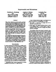
Fig. 1 gives an overview on the principles of the ISG approach. By taking high-level engineering information and by applying ISG construction rules, an executable system is generated, typically within 10 .. 75 minutes1. Then a feedback from the real system is available regarding the functional and non-functional properties. Formal Definition
Construction Rules
Executable System
Operational Testing Stress Testing Fault Injection Engineering Information Input
Standards Configuration Options Tool Support
Feedback Output
typically 10 .. 75 minutes
Figure 1: The ISG Approach of System Generation
1
The generation time depends mostly on the number of process types and amounts roughly to about 1 .. 2 minutes per process type. The upper limit has been observed for the MSL project (MSL1) which consists of about 40 process types.
2.1
The ISG Process of System Generation
With ISG testing and integration can be performed in top-down manner, yielding full visibility on the properties of the actual version (Fig. 2) during the whole lifecycle. This is different from the V-model approach for which a first feedback cannot be received before the coding phase and integration cannot be done before module testing. Hence, risks which are related to integration are identified very late, mostly too late to be able to solve a problem with little effort. The V-Model
The ISG-Model Bottom-Up
Top-Down Specification
Top-Down
Top-Down
Integration
Refinement
Design
Testing & Integration
Testing Coding Specification DesignCoding
Feedback
Feedback Testing
Integration
Refinement Testing Integration
Time
Time
Figure 2: ISG vs. the V-Model
Fig. 3 shows how the executable code is automatically generated from the user inputs. Such inputs are processed by ISG utilities, which generate the source code and the environment needed to build the executables. Having compiled the source code and built the executables, they are distributed across the network and executed. By instrumentation the information on the system's properties is produced and presented by an evaluation report after the execution. A user just has to provide the inputs (in terms of literals and figures defining the system's components and performance constraints), to start the generation process and then to wait until the window pops up which displays the evaluation report. By each iteration ISG transforms one consistent version of the system into the next one. There are a number of entries where the generation process may be restarted. Two principal entries are shown by Fig. 3: the "major" cycle which is required after a structural change and the "minor" cycle which may be executed in case of pure re-compilation, e.g. after update of a source file. Structural & Behavioural Refinements
Functional Refinements + UDF
Major
User Inputs
Cycle
Form Sheets
ISG Environment Utilities
Templates
Libraries
SDL + C
Minor Cycle
Source Code
Host/Target Environment
Executable Distributed Code
Execution Evaluation Report Result Analysis
Figure 3: The Automated Process Model of ISG
The user inputs define a system in terms of processes, Finite State Machines (FSM), incoming and outgoing data, the functions to process the data (called „User-Defined Functions“, UDF), nodes (CPUs) where the activity shall be executed, logical channels and performance properties and constraints such as timeout, expected CPU consumption, periods (including time jitter), amount of transmitted data. ISG automatically provides the infrastructure for data communication and scheduling, performance analysis, verification and validation for a given topology (Fig. 4). The application-specific processing of the data is performed by UDFs which can be plugged into the framework as provided by ISG. At the beginning (instrumented) stubs are generated by ISG, which ensure the system's execution right from the beginning. Later on the UDFs as provided by the user are plugged-in successively into the drawers (PID) provided by ISG. A UDF may also be generated automatically with ISG. ISG Generated Infrastructure behaviour/FSM
communication topology and distribution
timing and performance Process P1 UDF1-P1
Process P2 inter-process communication
UDF2-P1
UDF1-P2
by logical channels
UDF2-P2
UDF3-P1 PID
UDF = User-Defined Function for data processing FSM = Finite State Machine PID = Plug-In Drawer provided by ISG
Figure 4: The Automatically Generated Environment for Embedding of Application-Specific Functions
Application Specific Code
ISG
Environment Modelling
scheduling asynchronous synchronous
time-jitter
user-provided source code
UDF
stimulation
ISG-provided source code
UDF generated by ISG
synchronous source code
automated Reporting & V&V
Figure 5: ISG Supported Features
Fig. 5 shows the principal features of ISG to support an application: (1) to provide the infrastructure for data communication and scheduling, (2) to complement the application by its environment either for stimulation (including stress testing and fault injection) or to disturb
the system, (3) to embed user-provided or ISG-provided application specific code for data processing and to embed them within instrumented code, (4) to generate automatically UDFs from high-level user inputs. A standard format (DASIA’99) is used to exchange data. This format includes logical information about the the sender, the receiver, the transfered data and the time and duration of the transfer. Its contents may be translated into other exchange formats or derived from such formats provided that these formats also include the minimum information required for (timestamped) data exchange. As sender and receiver are defined on a logical level which is converted into the routing information by the output drivers, a change of the topology is easily possible without any need to change the logical definition of the system. Currently, such a change is possible at the time of system generation or distribution of the executables, but it may be extended to the existing dynamic reconfiguration2 as described by (RTL). To get information about performance like CPU consumption ISG either uses system services (e.g. in case of Unix platforms) or it provides itself the needed services as in case of the realtime operating system VxWorks. For monitoring of resources like memory consumption or buffer utilisation ISG instruments the source code. Currently, ISG generates C source code, but it may be ported to other programming languages as well. It also may interface with existing code supporting C interface standards. 2.2
Application Areas of ISG
Basically, ISG addresses system generation from scratch by making this process more efficient and less risky. However, due to the capability to embed user-defined code it may also interface with already existing code which is plugged into the ISG-provided skeleton as a UDF (see Fig. 4). From this point of view it may be applied to port legacy software to a modern platform: ISG provides (immediately) the infrastructure and the existing, platformindependent software is plugged in as UDF. Also, a bridge can be established from another tool environment, which is already, to ISG in order to take benefit from its testing, reporting, verification and validation capabilities. Components which require a complex hardware environment for integration and testing on system level, can easily be integrated with ISG on pure software level, which is less expensive more flexible regarding iterations and probably earlier available than a hardware platform. ISG is currently used in the technical area, e.g for the MSL project (MSL1, MSL2) and the CRISYS project (CRISYS). MSL is the „Material Science Laboratory“ of the International Space Station planned to fly in 2001/2002. In the CRISYS project ISG will be used for two applications acting as an integration and V&V platform for (1) a back-up power supply of a nuclear power plant and (2) a mail sorting and distribution system. Characteristic for the current „technical“ application domain are: - the number of process types is rather high and only a few instances exist for each process type (e.g. 40 process types and 50 instances in total for MSL),
2
This technology will be applied to the software of the Automated Transfer Vehicle (ATV) which is part of the International Space Station ISS.
- the instances may need to communicate directly via shared memory, - resources like memory and CPU power may be small. This is different from the „Information Technology“ (IT) domain of database processing, information management and client-server systems, using e.g. COBOL and SQL beside C and C++, with usually a high number of instances (clients) per application type and strict separation of the client’s address space. However, the concepts of ISG are not limited to the pure technical domain. The available infrastructure can be adapted with little effort to cover the needs of the IT domain, so that all the generation, verification and validation capabilities would be available for such applications as well. Also, the experience to automatically generate user-defined functions (UDFs) for data processing from user inputs can be well applied to areas where SQL, COBOL and C++ are used. 2.3
Future Evolution
The future evolution of ISG will be related to interface with existing user environments, to adapt ISG to other application domains, to increase the percentage of automatically generated UDFs, and to provide a user interface adequate for the application domain. According to a number of discussions it seems that the needed formalisation of user inputs (as required for automation) needs to be hidden as far as possible to get the automated approach accepted by the user. In case of MSL (MSL2) engineers used already spreadsheets intensively and a major part of the existing datasheets could be reused for the definition of the software. Therefore this representation was kept and a meta-model was established to introduce the required formal definition level. For other applications the adequate representation of user inputs needs to be discussed with the users. It is believed that the current datasheet-based representation can be still reused as an intermediate representation of ISG, into which the dedicated user representations are transformed. The essential point is to keep the informal world of a user, but to enhance it towards a higher degree of formalisation, e.g. by using a slightly different organisation which allows for formal checks. E.g. in case engineers are used to provide their inputs by specification and design documents, these documents could be organised such that the formal inputs appear within "informal" text and the user really does not recognise that the input scheme is formalised. 2.4
Summary on ISG
ISG automates the software development process and combines system generation with verification and validation. This allows to derive information about functional and nonfunctional properties from the real system right from the beginning. Due to automated instrumentation the real system itself can deliver information which in the past could only be provided by a separate prototype. As ISG has a modular structure and uses construction rules and templates for system generation, it can easily adapted to different application domains. The currently used format of user inputs can also be adapted to user needs, capable to request formal inputs in a „quasi-informal“ manner. The automation of the development process implies automation of maintenance.
3
Performance Engineering
This chapter explains the means for performance analysis which are automatically built-in by ISG into the operational software system. ISG checks the consistency of the behaviour, the compliance of achieved performance with performance requirements and the robustness of the system. It records timeouts, cycle overruns and exceeded deadlines. It compares the estimated CPU load with the measured one and provides a new estimation, so that a user can refine his performance estimations. The load figures are calculated for each instance of a process type ("cmdhandler" in Fig. 6 below) and for all instances. In case all instances of a processes need to execute on the same CPU („ONETARGET“ mode, e.g. at an early development phase when the target processors are not available), but they should be distributed across a network of CPUs, ISG estimates the load for each CPU (FCU and PSU in Fig. 6) from the „ONETARGET“ figure. Process
inst consumed time
1 2 3 4 5 6 7 7a 8
cmdhandler cmdhandler cmdhandler cmdhandler cmdhandler cmdhandler cmdhandler cmdhandler cmdhandler
all all 1 all 1 all 1 1 all
-
-
-
load % process
1374.55s 16.29s 67.48% 16.29s 67.48% 7.30s 30.24% 7.30s 30.24% 23.59s 97.72% 23.59s 97.72% 24.14s 100.00% 24.14s 100.00% -
load % all processes 4.66% 4.66% 2.09% 2.09% 6.75% 6.75% 6.90% 6.90%
-
-
CPU load %
Comment
1.192% 1.192% 0.534% 0.534% 1.726% 1.726% 1.766% 1.766%
duration tot_sequProg_busyTime instance_sequProg_busyTime tot_asyncIO_busyTime instance_asyncIO_busyTime tot_process_busyTime instance_busyTime tot_busyTime(corrected) tot_busyTime(system)
25.581% 15.613% 9.973%
Node
FCU FCU FCU FCU -
ONETARGET totalSystemUtilisation_mode= systemUtilisation_(estimated)_for_node FCU systemUtilisation_(estimated)_for_node PSU
Figure 6: Calculation of CPU Utilisation
A similar calculation is done for the network utilisation (Fig. 7). For each physical channel (as defined by the user) ISG counts the transmitted bytes which are exchanged between the CPUs (in the example there are two CPUs: FCU and PSU) and calculates the channel utilisation. When executing all the components of a distributed system on one processor only, a delay may be generated which represents the difference between communication by local channels (e.g. message queues, IPC) and remote channels such as UDP and TCP/IP.
#1 udp #2 udp overall all
fcu psu psu fcu psu fcu
468.00 887.00 1355.00
0.00% 0.01% 0.01%
#1 udp overall all
fcu fcu 19958.00 fcu fcu 19958.00
0.18% 0.18%
#1 udp overall all
psu psu 14895.00 psu psu 14895.00
0.14% 0.14%
Figure 7: Calculation of Network Utilisation
Also, the ISG report informs about the buffer utilisation (Fig. 8) so that the buffers can be optimised towards their actually used size. #Samples: #bufferStore: #bufferGet: #bufferFree: MaximumQueueLength: MeanValueOfQueueLength:
3563 1784 3562 1781 3 1.00
for for for for for for
acq_hdl acq_hdl acq_hdl acq_hdl acq_hdl acq_hdl
Figure 8: Information on Resource Consumption
Moreover, ISG provides information about the processing power of a certain processor type, so that it can easily be compared with other types. This is done by measuring the time needed to execute a dummy loop step (Fig. 9). Such figures may depend slightly on the compiler, of course. #CalibSamples: minExecTimePerDummyLoopStep: meanExecTimePerDummyLoopStep: maxExecTimePerDummyLoopStep:
22538 0.110us 0.133us 40.350us
loopStepsMin: loopStepsMean: loopStepsMax:
100.000 124.408 199.000
Figure 9: CPU Calibration
Moreover, response times are calculated by ISG. A user may identify the start of a handshake between two processes: a process sends a message to another process and expects a response. To measure the response time, the sending process (S) inserts the start time in the data exchange format, and the responding process (D, destination) inserts the actual time when it responds. Hence, each of the processes can measure the transmission time and the sender can calculate the overall response time. Fig. 10 shows the minimum, mean and maximum figures as provided by the ISG evaluation report for each of the actions executed during a state transition. The naming convention is: // ➠ // sdt1/init/init_serial_line -> daemonack/operational/cmdhandler #samples=4 resp(S->D->S)=(0.000000 44.543982 54.134011)ms resp(D->S) =(0.000000 19.197762 25.722027)ms Figure 10: Response Times
Reports also provided by ISG but not shown here are: "coverage of data processing actions", "list of non-covered actions", "coverage of states", "list of non-covered states", "executed state transitions", "exception report", "error injection report", "timer report", "timing and sizing budgets".
By timing diagrams (Fig. 11) more information on the event flow is provided (by clicking on an event the transmitted data are displayed). The data flow between the processes is shown by Message Sequence Charts (MSC). A MSC gives either detailed information on the exchanged data and the involved FSM (so that it can be used for debugging) or summary information on communication by a highly compressed timescale as shown by Fig. 12.
Figure 11: Timing Diagram on Events
Figure 12: Message Sequence Chart Describing the Overall Data Flow
4
Robustness Engineering
Robustness engineering is the consequent extension of performance engineering regarding risk reduction and demonstration of quality of service under stress and fault conditions. It can share all the means needed for performance engineering. But it requires additional means to demonstrate the system's robustness. Such means are autoamtically provided by ISG.
Robustness engineering deals with - fault prevention - fault removal - fault tolerance. ISG covers fault prevention by formal checks and automated construction of the system. Fault removal is supported by rejection of incorrect and inconsistent inputs, by automated insertion of run-time assertions, by giving a feedback on behaviour (received data, states, executed actions, exceptions), performance (cycle overruns, timeout, exceeded deadlines), by evaluation and presentation of results regarding coverage analysis, resource analysis, performance analysis, by supporting fault injection, automated test stimulation, stress testing, scaling of time. Regarding fault tolerance ISG implements exception handling on the level of the FSMs, e.g. for timeout conditions, illegal data inputs, and allows to define redundant communication channels. Management of redundant processors is supported on the level of FSMs, too. Fig. 13 shows the verification and validation concept of ISG: the automated system generation based on a formal definition (bottom), the checking and reporting capabilities to identify errors (top), and system stimulation (in the middle).
Checking Coverage, Analysis and Reporting Concept Formal Error Detection System Stimulation, Stress Testing, Fault Injection and Tracing
System Operations Cross-Checks
Built-In Checks
Automated System Generation Formal System Definition ISG
Figure 13: ISG Verification and Validation Concept
Three principal test modes exist: 1. testing related to the normal operational scenario 2. stress testing either by stimulation of a high number of process at a high input rate and/or by scaling of time 3. fault injection by stimulation with illegal inputs or by loss of data
Mode 1 and possibly mode 2 are a matter of performance engineering, while modes 2 and 3 are clearly a matter of robustness engineering. While the test objective of mode 1 is to prove absence of errors and the presence of the desired capabilities, the test objective of modes 2 and 3 is to create errors, but hopefully to fail with this intention. The errors which may be detected can be classified as a. errors detected by visual checks and tool support at pre-run-time (static checks) b. errors detected during execution due to error messages which cover e.g. illegal inputs to states, lack of resources like buffer overflow, exhausting of disk space and database, exceeded deadlines, cycle overruns c. errors detected at post-run-time by coverage and performance analysis e.g. non-covered states, too high response times.
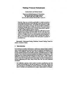
Starting with mode 1 (normal testing) a first set of errors will be recognised. But the removal of such errors does not imply that the system will be freee of errors. In case of overload situations a number of unsolved problems will come up, e.g. loss of communication capabilities due to overload of the processor, loss of operational capabilities of the operating system due to lack of disk space etc. Such situations are typical for e.g. client-server systems for which the load cannot be determinned in advance because the number of instances / clients is unknown or the load they are generating. Therefore it is necessary to expose the system to tests related to steps 2 and 3 in order to be sure that a system will not crash in case an overload situation occurs. Vice versa, the system design must consider such undesired situations in advance, e.g. by implementation of selfprotection mechanisms which help a system to survive. Then by execution of test modes 2 and 3 the prove can be given that the system is capable to tolerate stress and fault conditions. The commonly used test approaches like „testing with operational profiles“ (e.g. (Musa93)) aim to minimise occurence of faults during later operation, but they do not intend to remove every fault (e.g. Ehrlich93)). Frequently executed parts of a system are well tested, but rarely executed parts are excluded from testing, more or less. Testing is stopped when an estimation indicates that a sufficiently low probability for fault occurence is achieved according to the actually applied set of tests. As it is difficult to generate stress situation or faults, complex test software is required, e.g. to generate an overload condition which requires a large number of processes to be active, or partial loss of information. Therefore ISG has built-in capabilities for stress testing and fault injection. For each process type a stimulation rate and the type of fault injection can be specified which makes it easy to create an overload or to loose information. This can be done on a high abstraction level by giving patterns like wild card options. Hardware and software faults are recognised by a software system either as illegal or missing input. An illegal input prevents processing of the received data and generation of a result. Hence, an illegal input causes missing input. Therefore occurence of faults can be representatively modeled by loss of data (for testing of the exception handlers the illegal inputs must occur, of course, and loss of data is not sufficient). Fig. 14 shows the results of an experiment to measure the robustness of a system against loss of data. The probability to loose data has been increased from 0 to 1. For this example the coverage of states decreases suddenly from 100% to a small value already at probabilities close to zero. This shows that the system-under-test is not very robust regarding loss of data
and occurence of faults, respectively. Vice versa, if the system would be sufficiently robust such a test would document that the system fulfills the robustness requirements. Loss-Of-Data Probability 0 0.01 0.02 0.03 0.04 0.05 0.10 0.50 0.70 1.00
% Coverage of States 100 100 78.38 78.38 37.94 37.84 37.84 36.04 36.04 36.04
# Exceptions 200 129 212 186 93 120 270 355 557 840
Figure 14: Analysis of Robustness: An Example
A surprising result is that the number of exceptions does not monotonically increase with the fault injection probability: by loosing data the number of system activities decrease, and consequently the chance that an exception will occur decreases as well. When the minimum coverage of states is reached then the number of exceptions increases again, because no interference between decreasing number of actions and increasing number of lost data occurs anymore. Hence, the number of observed exceptions cannot be used as a measure for a system’s robustness. By robustness engineering different implementation choices may be evaluated. E.g. a strategy which increases robustness against loss of data, may cause an overload. Consider an application for which a process shall cyclically execute. A solution is to start the process once, and the process itself cares about generation of the next cyclic events: on reception of the actual event it requests for the next event. What is very critical in this case is that the process stops execution completely at first loss of a signal. So this approach is not very robust. Now, to get a higher probability to survive two signals could be issued, hoping that at least one signal will arrive. However, this solution ignores the reason why a signal may be lost: it may be lost due to an overload. But doubling of the signal rate increases the probability of an overload situation, and does not help at all, it makes the situation even worse. A robust solution is to make the signal generation independent of the data transfer, e.g. by using a cyclic software timer. Also, this reduces the data transfer rate because only the triggering event needs to be sent, but not the request for the next event. Hence, this is the optimum solution because it is robust against loss of data (even if an event is lost, the cyclic execution does not terminate), and it reduces the data traffic, i.e. the probability that an overload situation may occur. It seems to be very clear that such a problem can be detected by analysis. However, unfortunately this is very difficult because the potential impacts are hidden under normal conditions. Therefore it is very important to have an environment which makes it easy to generate stress and fault conditions like ISG does.
5
Relevance of the Results for The Information Technology Domain
Increase of productivity, risk reduction, higher software quality are keywords which surely are of interest in the domain of IT software, too. Therefore it is believed that the experience with ISG in the technical domain regarding formalisation and automation of the software development and maintenance process is of advantage for the IT domain as well. According to the current experience with ISG and the knowledge abbout IT applications it is believed that the current ISG approach can be tailored towards the IT domain. ISG can be applied to develop software from scratch, but it also may be used to embed existing software and to generate test environments for performance and robustness engineering. E.g. it automatically may generate a large number of clients and the needed legal or illegal inputs for stress testing and fault injection. For automation of the process model the dependencies between the different development steps were identified and described in a formal manner, so that the whole set of software and data can be kept consistent with minimum effort after a change. This also covers automated maintenance: the set of files of the current and the next version are passed to the ISG assistant tool which then decides which actions need to be taken. Automated and consistent maintenance of software is of interest for the IT domain as well, and the available knowledge about its organisation can be reused. Moreover, a lot of experience was collected regarding porting and automated installation of software. It has been observed that interfaces to „Commercial-Off-The-Shelf Software“ (COTS) may change or may depend on the actual configuration of a host. When installing an update or porting software to another, possibly similar platform such hidden dependencies may cause a number of problems. In worst case they are not immediately detected at installation time, but may occur during the later operational phase. Therefore, the installation process must check for such potential problems and test the correct execution. This is what ISG does when it is installed and executed.
6
Conclusions and Future Work
In the past, methods and tools concentrated only on the functional aspects during the development of a software system which caused a significant percentage of delivered systems to fail or prevented their delivery at all. It is now accepted that performance engineering is needed in order to avoid that software systems will not meet the non-functional requirements. Performance enginnering is mostly performed as a sepearate activity prior to or in parallel to the development of software using dedicated tools, being understood as prototyping activity. This approach is driven by (1) that the operational software is not ready for execution at an early development stage, and (2) that it is difficult and expensive to instrument it for performance analysis. Robustness engineering is considered as an extension of performance engineering towards getting software which behaves deterministic under stress and fault conditions. The required protection mechanism are usually strongly related to the implementation, and therefore it is difficult to built a representative prototype. Moreover, it is not sufficient to demonstrate that the prototype will behave correctly. This has to be shown by the real system. A solution to this problem is provided by ISG, an approach which automatically generates the infrastructure of a software application and data processing software. Beside speeding up the
development process ISG provides an inexpensive possibility to instrument the automatically generated source code such that performance, resource and robustness figures can be derived. As this capability is available right from the beginning of development a representative prototype is not needed. Regarding automated system generation a first step was to demonstrate the feasibility of a fully automated approach like ISG in the domain of real-time and/or distributed systems of small to medium size, but of high technical complexity. Due to its modularity ISG can be extended from the current application domain to other domains like IT, taking benefit of the available knowledge which has already been collected. This knowledge is related to the organisation of the automated generation and instrumentation of the code and the formalisation of the inputs and of the process model.
References CRISYS: Critical Instrumentation and Control System, ESPRIT project EP 25514 (1997-2000) DASIA99 R.Gerlich: Organising Incremental, Reusable and Automated Software Development, Eurospace Symposium DASIA’99 "Data Systems in Aerospace", May 17-21, 1999, Lisbon, Portugal ESA SP-447 (1999) 141-148 Ehrlich93: W.Ehrlich,B.Prasanna,J.Stampe,J.Wu: Determining the Cost of a Stop-Test Decision, IEEE Software, March (1993) 33 ISG: Gerlich, R: ISG, Instantaneous System and Software Engineering, User's Manual, Auf dem Ruhbuehl 181, D-88090 Immenstaad, 1999-2000 The ideas and implementation details related to ISG are property of Dr. Rainer Gerlich BSSE System and Software Engineering. They are protected by international copyright 1999 - 2000.All rights reserved Lustre: N.Halbwachs: Lustre Language Reference Manual, V5 (1997) MOVEP: Gerlich, R: An Implementation and Verification Technique for Distributed Systems, MOVEP’2k, Modelling and Verification of Parallel Processes, June 19-23, 2000, Nantes, France, Computer Science and Automated Systems Summer School,, http://www.ircyn.prd.fr/movep/, to be published in „Lecture Notes in Computer Science“, Springer-Verlag (2000) MSC: ITU-T Recommendations Z.120, Message Sequence Charts (MSC), Helsinki, 1993 MSL1: R.Gerlich, M.Birk, U.Brammer, M.Ziegler, K.Lattner: Automated Generation of Real-Time Software from Datasheet-based Inputs -The Process Model, the Platform and the Feedback from the MSL Project Activities, Eurospace Symposium DASIA’00 "Data Systems in Aerospace", May 22-26, 2000, Montreal, Canada, ESA (2000) MSL2: M.Birk, U.Brammer, M.Ziegler, K.Lattner, R.Gerlich: Software Development for the Material Science Laboratory on ISS by Automated Generation of Real-Time Software from Datasheet-based Inputs, Eurospace Symposium DASIA’00 "Data Systems in Aerospace", May 22-26, 2000, Montreal, Canada, ESA (2000) Musa93: J.D.Musa: Operational Profiles in Software-Reliability Engineering, IEEE Software, March (1993) 1432 ObjTime: ObjecTime, ObjecTime Limited,; 340 March Road, Suite 200, Kanata, Ontario, Canada K2K 2E4,
[email protected] OG:
ObjectGEODE, Verilog, 52, Avenue Aristide Briand; Bagneux; 92220; France,
[email protected]
OPNET: OPNET, MIL3 Inc., 3400 International Drive, NW-Washington, DC 20008, USA ROOM: B.Selic, G. Gullekson, P.T. Ward: Real-Time Object-Oriented Modelling, John Wiley & Sons (1994) RTL: R.Gerlich: Dynamic Configuration with Ada, 10th Annual National Conference on Ada Technology, Washington, February 24-27, 1992 Scade: SCADE tool, Verilog, 52, Avenue Aristide Briand; Bagneux; 92220; France
SDL: ITU Z.100, Specification and Description Language, SDL, Geneve (1989) SDT: SDT, Telelogic, Headquarters: Box 4128; S-203 12 Malmoe; Sweden. Vising address: Kungsgatan 6,
[email protected] Statecharts: D. Harel: Statecharts: A visual formalism for complex systems, Sci. of Comput. Prog., vol 8, (1987) 231-274 Statemate: Statemate/Rhapsody, i-Logix, Three Riverside Drive, Andover, MA 01810,
[email protected] StP:
Software Through Pictures, Aonix Corporate: 5040 Shoreham Place; San Diego, CA 92122,
[email protected]
Teamwork: Sterling Software, Corporate Headquarters: 300 Crescent Court, Suite 1200; Dallas, Texas 75201, http://www.sterling.com UML: Unified Modelling Language, http://www.rational.com/uml WB:
SES/workbench, 4301 Westbank Dr., Bldg. A, Austin, TX 78746 USA,
[email protected]