systems based on timed automata extended with a notion of real-time tasks. It
has ...... Sensor readings in legOS are available to the generated program as ...
the physical component in the subsystem plus a controller (i.e. a control program)
.
Nordic Journal of Computing
CODE SYNTHESIS FOR TIMED AUTOMATA TOBIAS AMNELL1 ELENA FERSMAN1 PAUL PETTERSSON1 HONGYAN SUN2 WANG YI1 1
Uppsala University, Sweden. {tobiasa,elenaf,paupet,yi}@docs.uu.se. 2 Technical University of Denmark, Denmark.
[email protected].
Abstract. We present a framework for the development of real-time embedded systems based on timed automata extended with a notion of real-time tasks. It has been shown previously that reachability and schedulability for such automata can be checked effectively using model checking techniques. In this paper, we propose to use the extended automata as design models. We describe how to compile design models to executable programs with predictable behaviours. The compiling procedure ensures that the execution of the generated code satisfies mixed timing, resource and logical constraints imposed on the design model. To demonstrate the applicability of the framework, a prototype C-code generator based on the legOS operating system has been implemented in the Times tool and applied to develop the control software for a production cell. The production cell has been built in LEGO equipped with a Hitachi H8 based LEGO Mindstorms control brick. Key words: real-time, timed automata, code synthesis, schedulability, case study.
1. Introduction A key facility of many commercial tools for development of embedded software is to automatically synthesise executable code (i.e. code generation) from design models. However, few of the existing tools are capable of producing software with predictable timing behaviours, i.e. code which is known a priori to satisfy given timing constraints. In fact, most of the commercial tools trust the software developers to resolve the timing issues e.g. whether all tasks will meet their deadlines, when the generated code is supposed to run on a specific target platform. In contrast, research tools such as Uppaal [Larsen et al. 1997] and Kronos [Bozga et al. 1998] are often dedicated to analysis and abstraction on high-level design descriptions. This has proven useful for finding errors and checking correctness properties in many case studies, e.g. [Bengtsson et al. 1996], [Lindahl et al. 1998], [Stauner et al. 1997] and [D’Argenio et al. 1997]. However, it provides little or no support for producing the actual program code to be executed in the final implementation. In this work, we aim at synthesis of executable code with predictable behaviours, from high level design specifications. We combine results and ideas from modelchecking, scheduling, and synchronous programming to develop a framework which Received February 7, 2003.
2
T. AMNELL, E. FERSMAN, P. PETTERSSON, H. SUN AND W. YI
supports, on one hand, formal specification, validation, analysis of design, and on the other hand, code generation which ensures that timing constraints are met when the generated code is executed on the target system. As a design language, we use timed automata extended with real-time tasks [Fersman et al. 2002]. In such extended automata, a transition is associated with a task (or several tasks) that is an executable program with given parameters, such as execution time, deadline, fixed priority etc. Intuitively, whenever an automaton takes a transition, its associated task is released for execution. Thus a discrete transition denotes an event releasing a task and the clock constraints on the transition (i.e. the guards) specify the possible arrival times of the associated task. When a task is released, it is inserted into the ready queue of the operating system and executed according to its scheduling policy. It has been shown that the schedulability checking problem for the model of extended automata is decidable for both non-preemptive [Ericsson et al. 1999] and preemptive [Fersman et al. 2002] scheduling policies. An automaton is schedulable with a given scheduling policy if, for all possible sequences of events accepted by the automaton the released tasks can be computed within their deadlines. The check is performed by transforming the original scheduling problem to a reachability problem of timed automata extended with subtraction operations on clocks. This means that, given a design model of a timed system, described as a set of automata running in parallel, it can be checked whether it is schedulable prior to its implementation provided that the computing times on the target hardware for the associated tasks are known. In this paper, we show how to compile a (verified) design model to an executable program preserving the mixed timing and logical constraints imposed on the model. Inspired by the design philosophy of synchronous languages e.g. Esterel [Berry and Gonthier 1992], we assume that the target real-time operating system and hardware ensure the synchrony hypothesis, i.e. the run-time of certain system functions is neglectable compared with the execution times and deadlines of the application tasks. Based on this assumption, we transform the control structure of an automaton to operating system functions and the associated tasks to light-weight threads. The compiling procedure should be applicable to a variety of target platforms that guarantee the assumption. To demonstrate the applicability, we have developed a prototype C-code generator on the legOS operating system for the LEGO Mindstorms control brick, equipped with an 8-bit Hitachi micro-processor. The code generator has been integrated in the Times tool [Amnell et al. 2002] and applied to develop the control software for a production cell built in LEGO and controlled by LEGO Mindstorms control bricks. The control program for the most central component, the two-armed robot, is designed, analysed and generated using the Times tool. The generated code has been compiled, downloaded, and executed on LEGO Mindstorms bricks. The rest of this article is organised as follows: Section 2 describes the syntax and semantics of design models that are timed automata extended with tasks. To extract executable behaviours from design models, we present a deterministic semantics for the extended automata. Section 3 shows how to implement the deterministic semantics on a small generic embedded operating system. Section 4 describes the modelling and design of a production cell using the extended automata. Section 5 is devoted to the analysis and synthesis of the control software for the production cell. Section 6 concludes the paper.
CODE SYNTHESIS FOR TIMED AUTOMATA
3
2. The Design Language In [Ericsson et al. 1999] and [Fersman et al. 2002], an extended version of timed automata with real time tasks is presented. The idea is to annotate each transition of an automaton with a task (an executable program with computing time and deadline), that will be triggered when the transition is taken. The triggered tasks will be scheduled to run according to a given scheduling policy. This provides a general task model for real time systems, which can be used to solve scheduling problems. In this paper, we adopt a more expressive version of timed automata with tasks. We allow that an automaton and the annotated tasks may have shared variables. The shared variables may be updated by the execution of a task (or the automaton) and their values may effect the behaviour of the automaton.
2.1 Syntax Assume a set of variables D ranged by u, v. We assume that the variables take values from finite data domains. The variables may be updated by assignments in the form: u := E where E is a mathematical expression. We use R to denote the set of assignments (e.g. u := u + 1). Real Time Tasks. Let P ranged over by P, Q, R, denote a finite set of task types (executable programs written in a programming language). A task type may have different instances that are copies of the same program with different inputs. We assume that the execution times and hard deadlines of tasks in P are known1 . Further assume that a task may update the data variables by the end of its computation using assignments in the form u := E (computed by the task and the value of E is returned when the task is finished). Thus, each task P is characterised as a triple denoted (C, D, A) with C ≤ D, where C is the execution time of P , D is the relative deadline for P and A is the set of assignments updating data variables. The deadline D is a relative deadline meaning that when task P is released, it should finish within D time units. We shall use C(P ), D(P ) and A(P ) to denote the execution time, relative deadline and set of assignments of P respectively. Timed Automata. Assume a finite set of actions Act and a finite set of realvalued variables C for clocks. We use a, b, τ etc to range over Act, where τ denotes a distinct internal action, and x1 , x2 etc to range over C. We use B(C) to denote the set of conjunctive formulas of atomic constraints in the form: xi ∼C or xi − xj ∼D where xi , xj ∈ C are clocks, ∼ ∈ {≤, }, and C, D are natural numbers. We use BI (C) for the subset of B(C) where all atomic constraints are of the form x ≺ C and ≺ ∈ { t t
◦ (l, σ, q)−→Sch (l, (σ[A(Hd(q))])+t, Run(q, t)) if (σ+t) |= I(l) and C(Hd(q)) = t where M (m) :: q denotes the queue with M (m) inserted in q and Hd(q) denotes the first element of q.4 The first rule defines that a discrete transition can be taken if there exists an enabled edge, i.e. the guard of the edge is satisfied. When the transition is taken, 3
Note that we fixed Run to be the function that represents a one-processor system. In case the task queue is empty we interpret the conditions C(Hd(q)) > t and C(Hd(q)) = t as true. Hence the two last transition rules becomes equal and corresponds to a delay transition in ordinary timed automata. 4
6
T. AMNELL, E. FERSMAN, P. PETTERSSON, H. SUN AND W. YI
the variables are updated according to the resets of the edge, and the tasks of the action (if any) are inserted into the queue. There are two kinds of delay transitions as defined in the second and the third rules. In the second rule, the transition corresponds to that the first task in the queue is executed. The transition is enabled when the invariants are satisfied and the task has not completed the execution during the delay. The transition results in updates of the clock variables and a decrease of the remaining execution time and deadline time of the task at the head of the queue. In the third rule, the transition corresponds to completing the execution of the task at the head of the queue. The delay is the same as the remaining execution time. When the transition is taken the variables are updated according to the assignment of the task. Note that we assume a fixed execution time C(P ) for a task. It is possible to extend the model and the analysis so that the execution times vary in an interval between best and worst case execution time. We shall omit Sch from the transition relation whenever it is understood from the context.
2.3 Analysis of Design Model It has been shown that reachability and schedulability are decidable problems for the class of timed automata extended with tasks both for non-preemptive [Ericsson et al. 1999] and preemptive scheduling policies [Fersman et al. 2002]. In this section we give the definitions of these and define the boundedness problem, which should also be checked prior to code-synthesis. For a more detailed description on how to check schedulability of task extended timed automata we refer the reader to [Fersman et al. 2002] and [Fersman et al. 2003]. We use the same notion of reachability as for ordinary timed automata: a
Definition 3. (Reachability) We shall write (l, σ, q)−→(l0 , σ 0 , q 0 ) if (l, σ, q) −→ t (l0 , σ 0 , q 0 ) for an action a or (l, σ, q)−→(l0 , σ 0 , q 0 ) for a delay t. For an automaton with initial state (l0 , σ0 , q0 ), (l, σ, q) is reachable iff (l0 , σ0 , q0 )−→∗ (l, σ, q). Thus a state (l, σ, q) is reachable if there is a sequence of transitions starting in the initial state (l0 , σ0 , q0 ) and ending in (l, σ, q). We shall use reachability analysis to check safety properties of design models to conclude that undesired situations (states) are not reachable. For example, we may check that the size of the task queue for all reachable states is bounded. Note that the boundedness is a useful property, which may be used for estimation of memory consumption. Further, we may use reachability analysis to check the schedulability of a design model prior to the final implementation. Definition 4. (Schedulability) A state (l, σ, q) where q = [P1 (c1 , d1 ), . . ., Pn (cn , dn )] is a failure denoted (l, σ, Error) if there exists i (i ∈ [1..n]) such that ci ≥ 0 and di < 0, that is, a task failed in meeting its deadline. An automaton A with initial state (l0 , σ0 , q0 ) is non-schedulable with scheduling policy Sch if and only if (l0 , σ0 , q0 )−→∗Sch (l, σ, Error) for some l and σ. Otherwise, we say that A is schedulable with Sch.
CODE SYNTHESIS FOR TIMED AUTOMATA
7
Intuitively, a system is schedulable if for all reachable states, all tasks are guaranteed to meet their deadlines. It should be noticed that schedulability implies boundedness but not the other way around, as clearly many bounded ready queues are not schedulable. In order to check the above properties of a system design, given as an extended timed automaton C (possibly a parallel composition C1 k . . . k Cn ), we will need to take the behaviour of its environment into consideration. Recall that in the extended model of timed automata adopted in this paper, new task instances are released at the action transitions, corresponding to input signals received from the environment of the controller C. To model the environment, we compose in parallel with C timed automata models E1 k . . . k Em of its environment, and analyse properties of the complete system design S Design = C k E1 k . . . k Em . We shall see in the next section that the code-synthesis is guaranteed to preserve safety, schedulability and boundedness properties. This means that these properties of a system design can be checked prior to its implementation.
2.4 Deterministic and Executable Semantics We shall consider S Design as a design model. Code synthesis is to generate executable code from the design model that implements the controller. In general the behaviour of the design model according to the operational semantics (cf. Definition 2) is non-deterministic. Our goal is to extract deterministic behaviour for the controller, preserving safety properties satisfied by the design model. Thus, our problem is essentially to resolve non-determinism. The sources of non-determinism in the operational semantics are time-delays and external actions. We use time non-determinism to mean that an enabled transition can be taken at any time-point within the time zone, while we use external nondeterminism to mean that several actions may be simultaneously present from the environment which results in several enabled transitions. We say that a transition g,a,r e = l −→ m is enabled in state s = (l, σ, q), denoted Enabled(e, s), when its guard is true i.e. σ |= g and the environment is ready to synchronise on the action a. We shall refine the design model for the controller as follows: ◦ External non-determinism is resolved by assigning priorities to transitions in the controller. Let Pr : E 7→ Z be a function assigning a unique priority to each edge, which defines an order that the guards of edges are evaluated in. If several transitions are enabled in a state, they should be taken in priority order. ◦ Time non-determinism is resolved by implementing the so-called maximalprogress assumption [Yi 1991]. Maximal-progress means that the controller should take all enabled action transitions until the system stabilises, i.e. no more action transitions are enabled. Similar ideas have been adopted in the asynchronous time model in the Statemate semantics of Statecharts [Harel and Naamad 1996] and the run-to-completion step of UML statecharts [Lilius and Paltor 1999]. We can now give a refined (deterministic) version of the operational semantics for extended timed automata:
8
T. AMNELL, E. FERSMAN, P. PETTERSSON, H. SUN AND W. YI
Definition 5. (Deterministic semantics) Let A = hN, l0 , E, I, M i be an extended timed automaton. Given a scheduling strategy Sch and a function Pr that assign priorities to edges the deterministic semantics is a labelled transition system defined by the rules: g,a,r
a
(1) (l, σ, q)−→(m, σ[r], Sch(M (a) :: q)) if Enabled(l −→ m, (l, σ, q)) and there is g,a,r no e ∈ E such that Pr(e) > Pr(l −→ m) and Enabled(e, (l, σ, q)) t
(2) (l, σ, q)−→(l, σ + t, Run(q, t)) if (σ + t) |= I(l) and C(Hd(q)) > t and for all e ∈ E and d < t such that ¬Enabled(e, (l, σ + d, q)) t
(3) (l, σ, q)−→(l, (σ[A(Hd(q))]) + t, Run(q, t)) if (σ + t) |= I(l) and C(Hd(q)) = t and for all e ∈ E and d < t such that ¬Enabled(e, (l, σ + d, q)) Clearly the behaviour of the controller according to the refined semantics is deterministic. Safety properties in the design model are preserved since the behaviour defined by deterministic semantics is included in the behaviour defined by the operational semantics. That is, all sequences of transitions (i.e. executions) of a design model for a controller according to the deterministic semantics can also be taken according to the operational semantics. Note that according to the semantics, we may have automata that exhibit zenobehaviours, that is, infinite sequences of action transitions within a finite time delay. Such automata correspond to non implementable design models, and they should be discovered by schedulability analysis as non schedulable. To simplify the analysis, we adopt the following syntactical restriction. We shall consider only automata in which each cycle contains at least one edge associated with a task.
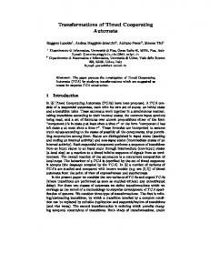
3. Code Synthesis Now we show how to transform a design model to an executable program according to its deterministic semantics. We assume a generic target platform which guarantees the synchronous hypothesis and on which the associated tasks will consume their given computing times to execute. As our transformation preserves the deterministic semantics, the schedulability of a design model will be preserved by the generated code when it is executed on the target platform. We assume that the target OS provides the following generic features: ◦ threads with unique priority levels, ◦ a scheduler based on fixed priority assignment, ◦ interrupt handling routines. The first two requirements are needed to map the notion of tasks from the design model to the generated code. Tasks have unique priorities in the model. Thus when they are mapped to threads in the implementation the threads must also have unique priorities. The last requirement is needed to encode control automata, which is done by interrupts using interrupt handing routines. The intended target platform for the generated code is a single embedded processor, but the organisation of the code is more easily illustrated by assuming two processors as shown in Fig. 1. The code of the controller and the tasks execute
CODE SYNTHESIS FOR TIMED AUTOMATA
9
Environment a b
c
Events Shared variables
P−finished?
x>10
Running task Sch()
Controller Control processor
Run() P
Scheduling queue
Execution Task processor
Fig. 1: The logical view of the executing system, with a control processor handling events from the environment and a task processor executing task code. Communication between the processors is limited to the task queue and shared variables.
on two separate logical processors, a control processor and a task processor. The interaction between the two is limited to the scheduling queue and shared variables. The control processor receives events from the environment and inserts tasks into the scheduling queue. The task processor executes the task at the head of the scheduling queue and updates the shared variables when a task is done. To realise the execution model on a single processor, we execute the code of the controller automata as a separate thread with a priority higher than all the other threads.
3.1 Handling Tasks and Variables Tasks are executed in threads, one thread for each task type, with priorities lower than the controller thread. Scheduling of task threads and management of the ready queue are handled by the target operating system. We assume boundedness of the queue length, meaning that the memory allocated for the task queue can be fixed at compile-time and no exception handling for queue overflow is needed at run time. Data variables in the design model are mapped to global integer variables in the generated code. To encode clocks, let sc be a global system clock. For each clock x in the timed automata, let xreset be an integer variable holding the system time of the last clock reset. The value of the clock is then (sc − xreset ), and a reset can be performed as xreset := sc.
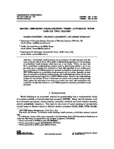
3.2 Encoding and Executing the Controller Automata In the generated program, the controller automata are encoded as four look-up tables and two functions, as shown in Fig. 2. Three of the look-up tables are static and used to encode the edges, the locations, and the synchronisations respectively. The fourth table is dynamic and used to hold the set of currently active edges, i.e. edges leaving the current control location (or locations, if the controller consists of parallel automata). We use ACTIVE to denote the list of active edges.
10
T. AMNELL, E. FERSMAN, P. PETTERSSON, H. SUN AND W. YI
All locations: out edges and tasks ACTIVE HIGH PRIO
loc1: e1, e2, e5
All edges in priority order
loc2: e6, e2
guard
assign
from
to
sync
...
...
...
...
...
...
Synchronisations: list of edges
LOW PRIO
sync1!: e3, e5, task3 guard−function
assign−function
sync1?: e4, e7, task3 ...
Fig. 2: Encoding of controller automaton in look-up tables.
The table containing all edges is sorted in priority order. For each edge there are five fields: guard, assign, f rom, to and sync. The guard and assign fields are references to code that when invoked will evaluate the guard and perform the assignments of the edge. The fields f rom and to are references into the table of locations. The field sync is either empty if the edge has no synchronisation label, or a reference to a list of edges having the complementary synchronisation label. In the table containing all locations, we store for each location a list of all edges leaving the location. In the table containing synchronisation labels, we store references to all edges at which the label occurs, and also the set of tasks associated with the label. Note that some of the information stored in the tables (such as the synchronisation label of an edge) is intensionally duplicated to improve efficiency. The list of active edges, ACTIVE, is managed by the procedure shown in Table I where we use a to denote the complementary synchronisation label of a, e.g. sync! for sync?. We use aut to denote a function that takes a location as parameter and returns an unique identifier for the automaton that the location belongs to. We use sort to denote a sorting function that takes as input two parameters: a list of edges, and a function assigning unique priorities to edges, and returns as output a list of edges sorted according to the assigned priorities. The procedure in Table I is executed by the controller thread whenever an event (such as timeout or arrival of an external event) has occurred. When executing, no new events are processed and the timers are not updated, i.e. the whole procedure is executed in a critical region. Note that this means that the tasks will not be able to update shared variables while the procedure is executing. Initially the list of active edges consists of all edges leaving the initial locations. The procedure scans ACTIVE in priority order and evaluates the corresponding guards. If a guard is found to be satisfied, there are two cases: ◦ no synchronisation - the assignment is performed and the information in the table of locations is used to update the list of active edges and to release any tasks associated with the edge. ◦ synchronisation - (i.e. the edge is labelled with an action label) the information in the table of synchronisations is used to find an active edge belonging to another control automata with complementary action label and satisfied
CODE SYNTHESIS FOR TIMED AUTOMATA
11
Table I: Procedure, in pseudo-code, that executes the encoded controller.
Initially: g,a,r ACTIVE := {l −→ l0 |l = l0 } ACTIVE := sort(ACTIVE, Pr) Algorithm: START: g,a,r for each l −→ l0 in ACTIVE do if σ satisfies g then if a = τ then σ := σ[r] remove {n −→ n0 |n = l} from ACTIVE add {n −→ n0 |n = l0 } to ACTIVE ACTIVE := sort(ACTIVE, Pr) q := Sch(M (a) :: q) goto START else g 0 ,a,r0
if exists m −→ m0 in ACTIVE s.t. σ satisfies g 0 and aut(m) 6= aut(l) then if a is sending then σ := σ[r]; σ := σ[r0 ] else σ := σ[r0 ]; σ := σ[r] remove {n −→ n0 |n = l ∨ n = m} from ACTIVE add {n −→ n0 |n = l0 ∨ n = m0 } to ACTIVE ACTIVE := sort(ACTIVE, Pr) q := Sch(M (a) :: M (a) :: q) goto START fi fi fi od
guard. If such an edge is found, the compound transition is performed i.e. the assignments of the two edges are performed, ACTIVE is updated and the tasks associated with action label are released. When a transition has been executed the procedure returns to START and reexamines the (updated) list of active edges to check for another transition to be taken. The procedure will continue to do so as long as enabled edges exist in ACTIVE. When there are no more enabled edges, the procedure will terminate and let the OS execute task threads. As an effect, the procedure implements a so-called run-to-completion step ensuring that the generated code has the maximal-progress
12
T. AMNELL, E. FERSMAN, P. PETTERSSON, H. SUN AND W. YI
behaviour assumed by the deterministic semantics (see Section 2.4). Note that since ACTIVE is always kept sorted and the procedure always scans from the head of the list, the implementation is also deterministic with respect to external actions.
3.3 Correctness In this section we argue for the correctness of the code synthesis by emphasising how the deterministic semantics (c.f. Definition 5) of timed automata with tasks is realised in the generated code. The three components of a semantic state (l, σ, q) are mapped to the following parts of the synthesised code: l: the source locations of the edges in ACTIVE (the list of active edges), σ: integer variables for the data variables in σ, and the difference between resettime and system time for the clocks in σ, q: the scheduling queue of the operating system. Note that there is no explicit representation of control location l in the synthesised code, instead the current control location is implicitly represented by the edges in ACTIVE. Initially, when the synthesised code starts to execute, the semantic state (l0 , σ0 , q0 ) is represented in the code as: l0 : ACTIVE is initialised with the edges leading out from the initial locations, σ0 : data variables are initialised to their initial values and the reset-time of clocks are initialised to the system time at startup, q0 : the scheduling queue is empty. The transition rules defined in the deterministic semantics (Definition 5) are mapped in the following way: a
(1) Discrete transition - (l, σ, q) −→ (l0 , σ 0 , q 0 ) is handled by the procedure in Table I. All edges that lead out from the source location are removed from ACTIVE and all edges that lead out from the target location are added to ACTIVE. Data variables are updated according to the assignments. Clocks are reset by assigning their reset-time to the current value of the system clock. t
(2) Delay transition without task termination - (l, σ, q) −→ (l, σ 0 , q 0 ) corresponds to the execution of a task. The location component of the state does not change during task execution. Data variables are not updated. Clocks are updated by the delay t during task execution since the difference between the last reset-time and the system clock will increase. In the queue q, the remaining execution time of the task at the head of the task queue, as well as the deadline of all tasks, will be t time units shorter. t
(3) Delay transition with task termination - (l, σ, q) −→ (l, σ 0 , q 0 ) corresponds to execution of a task. The location component of the state does not change during task execution. Data variables are updated by the assignment of the task. Clocks are updated by the delay t during task execution since the difference between the last reset-time and the system clock will increase. The queue is reduced by removing the task at the head of the queue, and the relative deadline of the other tasks will be t time units shorter.
CODE SYNTHESIS FOR TIMED AUTOMATA
13
The refinements introduced to resolve non-determinism are implemented as follows: Priority - Recall that all edges are assigned unique priorities. The controller thread evaluates the guards of the active edges in priority order from high to low. The first transition whose guard is satisfied is taken. In the case of synchronisation the complementary transition with the highest priority whose guard is satisfied is taken. The order of the active edges is maintained when replacing outgoing edges of the source location with those of the target location by resorting before proceeding. Maximal Progress - The code has maximal-progress behaviour since, when a discrete transition has been taken the list of active edges is checked again from the beginning. Only when no edge has a satisfied guard the controller will suspend and let other threads with lower priority (i.e. tasks) execute.
3.4 Prototype for legOS The code synthesis described above has been implemented in a version of the Times tool [Amnell et al. 2002] to generate code for the legOS [LegOS-team 2002] operating system — a small open source operating system for the Hitachi H8 processor — embedded into the LEGO Mindstorms RCX control brick. The OS is implemented in C and for simplicity we use C as implementation language for the tasks as well. The Hitachi H8 processor in the RCX unit is equipped with 32 kB of RAM, a typical setup for the type of embedded systems that our code generation is intended for. The I/O interface consists of three sensor inputs and three actuator outputs. In legOS threads are separate control flows that are scheduled on the CPU by the operating system. The scheduler implements preemptive fixed priority scheduling and handles up to 20 priority levels. Threads with equal priorities are executed in a round robin fashion. This limits the number of task types in the design to at most 19, since each task type needs a unique priority level and the highest priority level is reserved for the controller thread. Another limitation in the current version of legOS is in the interrupt handling. The OS provides so-called wake-up functions to program event handling. A wake-up function is a general mechanism provided by legOS that lets a thread wait for some condition (such as the release of a semaphore, a timeout, a key press etc.). A thread registers a boolean function that the scheduler will execute when it looks for the next thread to run, which it will do when the current thread is suspended or periodically every 20 ms 5 . To make sure that the control procedure of Table I is executed at every event handling, we encode the entire control procedure as a wake-up function that always returns false, and is associated to a task at highest priority level. In this way, the control procedure is ensured to be executed by the operating system (atomically and at OS priority level) just after every event handling, and just before the operating system determines the next task thread to be executed. For each task type a corresponding thread is created at boot time. The task threads contains a loop repeating a suspend call, and the task body to be executed. The suspend call registers a wake-up function that checks for a non-zero value of an element in the integer array release list. This array contains one element for each task type. When the controller releases a task the corresponding element is incremented, 5
The period of the scheduler (the time-slice) can be modified by recompiling the OS.
14
T. AMNELL, E. FERSMAN, P. PETTERSSON, H. SUN AND W. YI
deposit belt
press robot arm B sensor 3 (rotation) motor C (rotation) arm A
feed belt
output B (magnet)
ouput A (magnet)
Entry sensor 1 (light)
End sensor 2 (light)
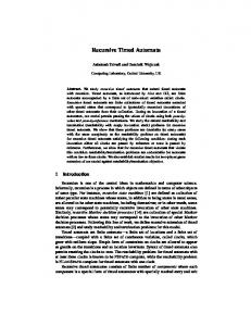
Fig. 3: The LEGO Production Cell.
so that the wake-up function of the task thread will return and resume the task thread. When the task body has executed the corresponding element in the release list is decremented, and the thread is suspended again at the start of the loop. Note that since priorities are fixed, the release list can be used as a representation of the current state of the ready queue. Sensor readings in legOS are available to the generated program as variables which are updated independently by the hardware. Sensor variables are either read by the task code, or used directly in guards of the control automata. This means that checking if a transition is enabled becomes a condition only involving variables (external and other), i.e. essentially the same as a guard. In the current prototype we associate tasks with locations instead of edges. The tasks are released when the location is entered. Such design models can easily be transformed into models with tasks on edges by associating the task of a location with all edges leading to the location. Furthermore we impose the syntactic restriction that a control automaton may not use both a sending and a receiving action label with the same name (e.g. not both sync! and sync? in the same automaton).
4. Modelling and Design of a Production Cell In this section, we show how to use our design language to model and design the control software for an industrial robot. The production cell is a unit in a metal plate processing plant in Karlsruhe. The model has been developed by FZI in Karlsruhe [Lewerentz and Lindner 1995] as a benchmark example of concurrent and safety-critical system software development. In this paper, we use a LEGO model of the production cell based on the model developed by FZI but with some simplifications. The LEGO production cell system contains four subsystems, the feed belt, the robot, the press and the deposit belt, corresponding to the physical components as shown in Fig. 3. Each of the subsystems performs a specific operation during the plate processing:
CODE SYNTHESIS FOR TIMED AUTOMATA
15
Fig. 4: The overall control structure.
The feed belt transfers a plate from the entry position to the end position where the robot arm named arm A can pick up the plate. The press forges the plate delivered by arm A of the robot, and the forged plate is unloaded from the press by arm B of the robot. The robot moves to the position where arm A points to the feed belt and picks up a plate. It then rotates until arm A points to the press where arm A delivers a plate. When a plate has been forged in the press, it moves to the position where arm B points to the press and picks up the forged plate. Afterwards, the robot rotates until arm B points to the deposit belt where it delivers the plate. The deposit belt receives a forged plate from arm B of the robot.
4.1 Overall Control Structure Each subsystem of the feed belt and the robot comprises sensors and actuators for the physical component in the subsystem plus a controller (i.e. a control program) for controlling the sensors and actuators. In our version of the production cell, both the press and the deposit belt contain only the physical components (without any sensor and actuator attached) as media for the robot to convey a plate. The status of a plate in both components are modelled in the robot controller by means of internal variables. The overall control structure of the production cell is sketched as in Fig. 4. Robot Controller. The robot controller is composed of two processes (or subcontrollers), RobotControl and MoveTo as shown in Fig. 4. The RobotControl process controls the overall motions of the robot, and communicates with both the feed belt controller and the local process MoveTo. The MoveTo process controls the robot movements according to the rotation sensor (i.e. sensor 3 in Fig. 3) information and the requests from RobotControl. The RobotControl process communicates with the feed belt controller by means of the shared variable platePos which indicates whether there is a plate on the feed belt. It communicates with MoveTo by means of communication channels i.e. startM to start the robot movement and stopM to stop the robot movement.
16
T. AMNELL, E. FERSMAN, P. PETTERSSON, H. SUN AND W. YI
Fig. 5: The automaton RobotControl. Labels in bold font indicate associated tasks.
Feed Belt Controller. The feed belt controller is composed of the BeltPosition process and the Alarm process. The BeltPosition process updates the positions of the plates on the feed belt periodically after they are detected by the light sensor. The Alarm process handles the light sensor (i.e. sensor 1 in Fig. 3) at the entry position of the feed belt. The light sensor senses the arrival of a plate on the feed belt. The communication between BeltPosition and Alarm is through the shared variable platePos which indicates the position of a plate on the belt. Note that the feed belt controller cannot stop the belt. The bricks will be picked up “on-the-fly” by the magnet on arm A.
4.2 Robot Controller Model The robot controller is modelled as two extended timed automata, named RobotControl and MoveTo. The shared variable platePos is modelled by an integer array Pos, and the communication channels startM and stopM are respectively modelled by synchronisation channels start and stop, together with a shared integer variable Goal that sets the goal position that the robot should reach. Automaton RobotControl. Fig. 5 shows the concrete model of the automaton RobotControl. Recall that in our prototype implementation tasks are associated with locations. In the automata shown in this section and in Appendix A, tasks are indicated as labels with bold font in the locations. In Fig. 5, Pos[0] is the first element in array Pos. Pos[0]>-1 indicates that there is a plate on the feed belt, Pos[0]==-1 indicates that there is no plate on the feed belt, and Pos[0]==0 indicates that the plate is at the position where arm A of the robot can pick it up. The boolean variable PlateInPress is used to model the status of the press (TT means that there is a plate on the press and FF means no plate on the press).
CODE SYNTHESIS FOR TIMED AUTOMATA
17
The constant PRESS T is used to model the time needed for the press to forge a plate, and the constant PREPARE T is used to model the time needed for the press to be ready to process a new plate. The clocks PressTime and PrepareTime are respectively used to measure whether PRESS T and PREPARE T are reached. The boolean variables PlateOnA and PlateOnB are used respectively to indicate the status of arm A and arm B. PlateOnA==TT denotes that arm A of the robot holds a plate, and PlateOnA==FF denotes that arm A is empty. PlateOnB==TT denotes that arm B of the robot holds a plate, and PlateOnB==FF denotes that arm B is empty. The boolean variable TaskDone is shared with the tasks released by the process. TaskDone==TT denotes that the current task e.g. the pickup task of arm A is finished, and TaskDone=FF denotes that the current task has not finished yet. The constants WAIT POS, FB POS, PRESS A POS, PRESS B POS and DB POS are five goal positions for the robot to reach in the robot working space. The automaton is initially at location AtW8, corresponding to that the robot is waiting for the control commands (or control events). The rest of the locations can be classified into three groups corresponding to the robot actions: ◦ The robot is moving from one position to the other, e.g. the locations Moving2FB and Moving2PrB. At the former location the robot is rotating so that arm A points to the feed belt, and at the latter the robot is rotating so that arm B points to the press. While waiting in these locations MoveTo control the movement of the robot. ◦ The robot is waiting for an event, e.g. the locations W8AtFB and AtPressB. The former represents that the robot stops at the position where arm A points to the feed belt and waits for the event Pos[0]==0, and the latter that the robot stops at the position where arm B points to the press and waits for the event PlateInPress==TT. ◦ The robot is carrying out the pickup or drop tasks, e.g. the locations PickUpA and DropA. At the former location arm A is picking up a plate from the feed belt, and the latter arm A is dropping the plate onto the press. On each of the edges to PickUpA, PickUpB, DropA and DropB, there is a executable task associated. For example, on the edge to PickUpA the task PickUpA is released for arm A to pick up a plate from the feed belt, while the edge to DropA is associated with the task DropA by which arm A drops a plate onto the press. Automaton MoveTo. The automaton MoveTo is shown in Fig. 6. The variable RobotAngle stores the sensor information about the current robot position. The value in ROTATION 1 stores the updated robot position while the robot is moving. Clock x is used to guarantee that RobotAngle is updated before it is used. The automaton is initially in location Entry corresponding to that the robot stops and waits for the signal from RobotControl over channel start. Having received the signal the task RdAngSen is released that reads the sensor information about the current robot position into the variable RobotAngle and the automaton moves to location Read. The task RdAngSen has deadline 16, see Appendix A, so the invariant x ≤ 30 together with the guards x = 30 on the outgoing edges will guarantee that RobotAngle is updated before the location is left. Based on the value in RobotAngle, the automaton moves either to location MR if RobotAngle ≤ Goal or to location ML if RobotAngle ≥ Goal, or to location Entry if RobotAngle = Goal.
18
T. AMNELL, E. FERSMAN, P. PETTERSSON, H. SUN AND W. YI
Fig. 6: The automaton MoveTo.
On the edge to location MR, the associated task MvRight commands the motor to rotate clockwise the robot. When the robot is in the desired position, i.e. ROTATION 1 = Goal, the automaton takes a transition to location SR. Similar to MR, on the edge to ML, the associated task MvLeft commands the motor to rotate anti-clockwise the robot. When the robot is in the desired position, i.e. ROTATION 1 = Goal, the automaton takes a transition to location SR. On both edges to SR, an associated task StopRobot is released to stop the motion of the robot. The automaton takes an urgent transition to location Entry when the robot is stopped, at the same time it informs RobotControl over channel stop.
4.3 Feed Belt Controller Model Similar to the robot controller, we use two timed automata extended with real-time tasks to model the two processes of the feed belt controller. The two automata BeltPosition and Alarm are given in Appendix A. Automaton Alarm. The automation Alarm is shown in Fig. 8 in Appendix A. Before it enters the initial location Calib the task Calib is released that performs calibration of the background light by measuring the mean light value, and saves it in the shared variable normalLight. Finally the task sets the boolean variable AlarmTaskDone to TT. When the sensor is calibrated, i.e., AlarmTaskDone==TT, the automaton takes a transition to location WaitFrontEdge. In location WaitFrontEdge, the automaton waits until the light value measured by sensor 1 (cf. Fig. 3) falls below 80% of the normal light. This indicates that the front end of a plate has passed through. The automaton then moves to location WaitBackEdge, where it waits for the whole plate to pass through the sensor, i.e. the measured light value rises to above 90% of the normal light. Once the whole plate has passed through the sensor, the automaton takes a transition to location AtStart and releases the AtStart which inserts a value into the array Pos . In location AtStart, the clock ArrivalTime is used to measure the time elapsed since the plate was detected. When it reaches to the value equal to SAFE CALIB, it
CODE SYNTHESIS FOR TIMED AUTOMATA
19
is safe to accept a new plate and return to Calib. The time constant SAFE CALIB is obtained by experiments. Automaton BeltPosition. The automaton BeltPosition is shown in Fig. 9 in Appendix A. It is initially in location Idle. When there is a plate on the belt, indicated by Pos[0]>-1, the automaton moves to location Active and releases task UpdatePos. In location Active, the task UpdatePos is released periodically to update the positions of the plates in array Pos. The period is represented by an invariant x =0?Pos[i]-1:-1)
RobotControl DropA
4
16
2
DropB
4
13
1
PickUpA
4
10
4
PickUpB
4
17
3
De-activate magnet on arm A. TaskDone:=TT De-activate magnet on arm B. TaskDone:=TT Activate magnet A. Remove value from Pos. ∀i Pos[i]:=Pos[i+1], Pos[BRICKS-1]:=-1, numBricks:=numBricks-1, TaskDone:=TT, Activate magnet on arm B. TaskDone:=TT
MoveTo MvRight
4
10
8
MvLeft
4
10
7
RdAngSen
4
16
9
StopRobot
4
10
10
Start motor to rotate robot rightwards. RobotAngle:=ROTATION_1 Start motor to rotate robot leftwards. ROB_DIR:=CW Read rotation sensor and convert to degrees. RobotAngle:=ROTATION_1 Stop rotation motor. ROB_DIR:=STOP
CODE SYNTHESIS FOR TIMED AUTOMATA
Appendix A.1 Query File /∗ Robot can become ready to pick up a brick from the feedbelt. ∗/ E( RobotControl.W8AtFB and Pos[0]==0) /∗ Scheduler can execute task to pick up a brick from the feed belt. ∗/ E( SCHEDULER.RUN PickUpA ) /∗ Robot arm B can reach the position of the press. ∗/ E( RobotControl.AtPressB ) /∗ Robot arm A can reach the position of the press. ∗/ E( RobotControl.AtPressA ) /∗ Scheduler can execute task (released by robot controller) to drop brick from arm A to the press. ∗/ E( SCHEDULER.RUN DropA ) /∗ Robot can never reach a state where it is waiting for press to complete, with arm B at the position of the press. Thus, location W8P1 is dead-code in the robot controller model. ∗/ A[ ]not( RobotControl.W8P1 ) /∗ Robot can never reach a state where it is waiting for press to become ready (with arm A at the position of the press). Thus, location W8P2 is dead-code in the robot controller model. ∗/ A[ ]not( RobotControl.W8P2 ) /∗ Scheduler can execute task (released by robot controller) to picked up brick from press with arm B. ∗/ E( SCHEDULER.RUN PickUpB ) /∗ Scheduler can execute task (released by robot controller) which drop brick from arm B on the deposit belt. ∗/ E( SCHEDULER.RUN DropB ) /∗ The robot controller is never waiting unnecessarily at the pick-up
27
28
T. AMNELL, E. FERSMAN, P. PETTERSSON, H. SUN AND W. YI
position of the feed belt. If it is there, it is because a brick has been detected on the feed belt (but perhaps not yet arrived to the pick-up position). ∗/ A[ ]( RobotControl.W8AtFB imply Pos[0]>=0 ) /∗ When the controller is waiting for a plate there should be no plate on arm A. ∗/ A[ ] not( RobotControl.AtW8 and RobotControl.PlateOnA==TT) /∗ Whenever task PickUpA is executing, a brick is at the pick-up position of the belt. ∗/ A[ ]( SCHEDULER.RUN PickUpA imply Brick.AtPickUp ) /∗ The pos of robot is always in the interval [FB POS,DB POS]. ∗/ A[ ]( ROTATION 1>=FB POS and ROTATION 1=1 ) /∗ Boundedness Analysis: The nr of simultaneously released task is bounded to 3. ∗/ A[ ]( (SCHEDULER.n0 + SCHEDULER.n1 + SCHEDULER.n2 + SCHEDULER.n3 + SCHEDULER.n4 + SCHEDULER.n5 + SCHEDULER.n6 + SCHEDULER.n7 + SCHEDULER.n8 + SCHEDULER.n9 + SCHEDULER.n10 ) EDIT WITH CARE! -1); case T6: return (RobCtrl PlateInPress==TT && Pos[0]==-1); case T7: return (TaskDone==TT); case T8: return (RobCtrl PlateInPress==FF && Pos[0]==-1); case T10: return (TaskDone==TT); case T11: return (RobCtrl PlateOnA==FF); case T12: return (RobCtrl PlateOnB==TT); case T13: return (RobCtrl PlateOnB==FF); case T14: return (RobCtrl PlateOnB==FF); case T16: return (TaskDone==TT); case T18: return (Pos[0]>-1 && RobCtrl PlateOnA==FF); case T19: return (Pos[0]==-1 && clock(RobCtrl PressTime) > PRESS T && RobCtrl PlateInPress==TT); case T20: return (clock(RobCtrl PrepTime)> PREP T && RobCtrl PlateOnA==TT); case T22: return (Pos[0]==-1); case T23: return (Pos[0]>-1 && RobCtrl PlateOnA==FF); case T25: return (clock(MoveTo x)==30 && RobotAngleGoal); case T28: return (ROTATION 1==Goal); case T29: return (ROTATION 1==Goal); case T30: return (clock(MoveTo x)==30 && RobotAngle==Goal); case T31: return (AlarmTaskDone==TT); case T32: return (clock(Enter ArrivalTime)>= Enter SAFE CALIB); case T33: return (LIGHT 290∗normalLight/100); case T35: return (Pos[0]>-1); case T36: return (clock(UpdPos x)==UpdPos UpdTime && Pos[0]>-1); case T37: return (clock(UpdPos x)==UpdPos UpdTime && Pos[0]==-1); case T1: case T4: case T9: case T15: case T17: case T21: case T24: case T27: return true; } /∗ case ∗/ return false; } // Perform assignments on transition a void assign(char a) { switch(a) { case T2: RobCtrl PlateOnA=TT; Goal=PRESS B POS; break; case T3: TaskDone=FF; break;
} trans t trans[NB TRANS] = { {0,RobCtrl Mv2PrB,RobCtrl AtPressB,stopS}, {0,RobCtrl S0,RobCtrl Mv2PrB,startR}, {0,RobCtrl W8AtFB,RobCtrl S0,-1}, {0,RobCtrl Mv2FB,RobCtrl W8AtFB,stopS}, {1,RobCtrl AtW8,RobCtrl Mv2FB,startR}, {1,RobCtrl AtW8,RobCtrl Mv2PrB,startR}, {0,RobCtrl S1,RobCtrl AtPressB,-1}, {0,RobCtrl AtPressB,RobCtrl MvTwPr,startR}, {0,RobCtrl MvToPrA,RobCtrl AtPressA,stopS}, {0,RobCtrl S2,RobCtrl AtPressA,-1}, {0,RobCtrl AtPressA,RobCtrl AtPress,-1}, {0,RobCtrl AtPress,RobCtrl Mv2DB,startR}, {0,RobCtrl AtPress,RobCtrl Mv2W8,startR}, {0,RobCtrl Mv2W8,RobCtrl AtW8,stopS}, {0,RobCtrl Mv2DB,RobCtrl S3,stopS}, {0,RobCtrl S3,RobCtrl AtDB,-1}, {0,RobCtrl AtDB,RobCtrl Mv2W8,startR}, {0,RobCtrl AtPressB,RobCtrl Mv2FB,startR}, {0,RobCtrl AtPressB,RobCtrl S1,-1}, {0,RobCtrl AtPressA,RobCtrl S2,-1}, {0,RobCtrl MvTwPr,RobCtrl Branch,stopS}, {0,RobCtrl Branch,RobCtrl MvToPrA,startR}, {0,RobCtrl Branch,RobCtrl Mv2FB,startR}, {1,MoveTo Entry,MoveTo Read,startS}, {0,MoveTo Read,MoveTo MR,-1}, {0,MoveTo Read,MoveTo ML,-1}, {0,MoveTo SR,MoveTo Entry,stopR}, {0,MoveTo MR,MoveTo SR,-1}, {0,MoveTo ML,MoveTo SR,-1}, {0,MoveTo Read,MoveTo Entry,stopR}, {1,Enter S0,Enter W8FrontEdge,-1}, {0,Enter S1,Enter S0,-1}, {0,Enter W8FrontEdge,Enter W8BackEdge,-1}, {0,Enter W8BackEdge,Enter S1,-1}, {1,UpdPos Idle,UpdPos Active,-1}, {0,UpdPos Active,UpdPos Active,-1}, {0,UpdPos Active,UpdPos Idle,-1} };
CODE SYNTHESIS FOR TIMED AUTOMATA
unsigned char loc[NB TRANS+NB LOC] = { T5,T6,tid NOP/∗AtW8∗/, T8,T18,T19,tid NOP/∗AtPressB∗/, T1,tid NOP/∗Mv2PrB∗/, T2,tid PickUpA/∗S0∗/, T3,tid NOP/∗W8AtFB∗/, T4,tid NOP/∗Mv2FB∗/, T7,tid PickUpB/∗S1∗/, T9,tid NOP/∗MvToPrA∗/, T11,T20,tid NOP/∗AtPressA∗/, T10,tid DropA/∗S2∗/, T12,T13,tid NOP/∗AtPress∗/, T15,tid NOP/∗Mv2DB∗/, T14,tid NOP/∗Mv2W8∗/, T16,tid DropB/∗S3∗/, T17,tid NOP/∗AtDB∗/, T21,tid NOP/∗MvTwPr∗/, T22,T23,tid NOP/∗Branch∗/, T28,tid MvRight/∗MR∗/, T25,T26,T30,tid RdAngSen/∗Read∗/, T24,tid NOP/∗Entry∗/, T27,tid StopRobot/∗SR∗/, T29,tid MvLeft/∗ML∗/, T31,tid Calib/∗S0∗/, T33,tid NOP/∗W8FrontEdge∗/, T32,tid AtStart/∗S1∗/, T34,tid NOP/∗W8BackEdge∗/, T35,tid NOP/∗Idle∗/, T36,T37,tid UpdPos/∗Active∗/ };
31
int MvLeft() { TASK BEGIN(MvLeft) // Start robot motor moving left motor c dir(fwd); motor c speed(100); TASK END } int MvRight() { TASK BEGIN(MvRight) // Start robot motor moving right motor c dir(rev); motor c speed(100); TASK END } int PickUpA() { TASK BEGIN(PickUpA) int i, temp; // Activate the magnet on arm A motor a speed(MAX SPEED); // Shift the values in the pos array. // Update the first (shared) element last. temp = Pos[1];
#include ”legos kernel.h” for( i=1; i= 0) ? (Pos[0]-1) : -1) ; TASK END } int main(int argc, char ∗∗argv) { Prodcell init(); execi( execi( execi( execi( execi( execi( execi( execi( execi( execi( execi(
&AtStart, 0, NULL, 12, SMALL STACK); &Calib, 0, NULL, 11, SMALL STACK); &DropA, 0, NULL, 2, SMALL STACK); &DropB, 0, NULL, 1, SMALL STACK); &MvLeft, 0, NULL, 7, SMALL STACK); &MvRight, 0, NULL, 8, SMALL STACK); &PickUpA, 0, NULL, 4, SMALL STACK); &PickUpB, 0, NULL, 3, SMALL STACK); &RdAngSen, 0, NULL, 9, SMALL STACK); &StopRobot, 0, NULL, 10, SMALL STACK); &UpdPos, 0, NULL, 5, SMALL STACK);
// Reset clocks reset(RobCtrl PressTime); reset(RobCtrl PrepTime); reset(MoveTo x); reset(Enter ArrivalTime); reset(UpdPos x); execi( &controller, 0, NULL, PRIO HIGHEST, SMALL STACK); return 0; }
Appendix B.2 Run-time system // legos kernel.h: The kernel functions that // executes the controller. // Deterimines if it is possible to // synchronise on a channel. // // parameter: sync, channel id, i.e. index // into the chanusage array. // // return: 0, if synchronisation is not // possible, transition id of the // complementary transition if it is. int check synch(unsigned char sync) { while( chanusage[sync] < NB TRANS ) { if( trans[chanusage[sync]].active && eval guard( chanusage[sync] ) ) return chanusage[sync]; sync++; } return false; } // Update the list of active transitions, // and release task of target location. // // parameter: trn, the transition taken. void clear and set (unsigned char trn) { int jj; // Clear outgoing transition from source jj=trans[trn].from; do { trans[loc[jj]].active=0; } while(loc[++jj]