Wireless infrared is an attractive alternative for short-range in- door communications. However ... However, beside these advantages it is known that IR transmis-.
CODING LIMITS FOR SHORT RANGE WIRELESS INFRARED TRANSMISSION Mike Wolf and Martin Haardt Ilmenau University of Technology, Communications Research Laboratory, P. O. Box 10 05 65, 98684 Ilmenau, Germany Phone: +49 (3677) 69-2619, Fax: +49 (3677) 69-1195 {mike.wolf, martin.haardt}@tu-ilmenau.de
ABSTRACT Wireless infrared is an attractive alternative for short-range indoor communications. However, mainly as a result of the physical properties of the detector, one serious problem is the power efficiency of the transmission. Under the assumptions of a fixed average optical power and additive white Gaussian noise, we derive the maximum coding gains attainable with optimized On-Off Keying, where ”optimized” refers to the probability of the logical ”1” pulses in the transmitted data stream. Uncoded On-Off Keying acts as the reference scheme. We also consider orthogonal pulse-position modulation, having favorable spectral characteristics, with and without additional coding and compare the corresponding coding gains with the limits for binary transmission. 1. INTRODUCTION IR radiation exhibits a number of characteristics which qualify it as a concrete alternative to radio frequency (RF) for short range indoor transmission. First of all, IR takes advantage of a completely unregulated and unlicensed spectral range with a bandwidth of several THz. Since IR radiation does not propagate through walls, systems operating in separate rooms do not interfere with each other; additionally, the optical medium promises high security against eavesdropping. However, beside these advantages it is known that IR transmission is associated with some serious problems. One of the most challenging is the limited power efficiency. As shown in [1], if IR is directly compared to RF transmission, IR suffers first of all from a strongly reduced receiver sensitivity. IR loses against RF mainly as a result of the different physical principles of the detectors. While the radiation power is available at the output of an antenna as electrical power, the IR detector converts it to a current. The magnitude of this current is physically limited by the photodiode’s sensitivity. Even if only the noise generated by the first input stage of the IR-detector is considered, the receiver sensitivity is much worse than in the RF-case. However, it is well known that the noise of an IR-detector is mainly determined by the shot noise caused by received background light. Since the first diffuse 1 Mb/s IR-system was proposed by Gfeller [2] in 1979, great efforts have been made to increase power efficiency (as well as the data rate) of non-directional arrangements. Besides classical approaches such as power efficient modulation schemes, non-imaging concentrators or optical filters in the last decade techniques using transmitter and receiver arrays to divide the covered angular range into different sectors have become more and more important [3, 4]. The main purpose of this paper is to discuss the advantages in
regard to the power efficiency which can be attained due to channel coding. We consider only coding limits and do not propose practical implementations of coding schemes — with the exception of Pulse-Position Modulation (PPM) which can be considered a coding scheme. The investigations are made under the assumptions of a fixed average optical power and white Gaussian receiver noise, which is assumed independent form the signal. These constraints are not applicable for fiber optics or highly directed optical free space links (for instance for satellite communications). For this reason we focus only on non-directed short range wireless IR indoor-transmission. Additionally, only binary (and necessarily unipolar) transmission is considered, where ”binary” refers to the possible variation of the pulse amplitudes, i.e., PPM is also considered. Subcarrier (or multiple subcarrier) modulation will not be taken into account, since a further power efficiency drawback is introduced by the required DC-component [5]. In the next section we introduce an OOK (On-Off Keying) transmission model. Note that OOK is equivalent to unipolar binary transmission. It follows the description of the reference transmission scheme: throughout the paper, uncoded OOK acts as the reference in regard to the coding gains1 and the code rates. In the two major sections 4 and 5, the maximum coding gains attainable with optimized OOK-transmission and with PPM are derived and discussed. 2. OOK TRANSMISSION MODEL As a result of the limited temporal coherence of the optical transmitters commonly used and the inherent spatial diversity provided by large area photodiodes, it is straightforward to model the optical channel as a linear time invariant system, taking optical instantaneous powers (and not amplitudes) as its input and output. The photodiode with sensitivity R, however, converts the impinging optical power into a current, which is an amplitude. Throughout the paper, distortion-less transmission is assumed, i.e., the photodiode is fully described by R, the channel impulse response is h(t) = δ(t). In the case of OOK, the transmitted optical signal ptx (t) can be denoted as X ptx (t) = si ψ(t − iT ), (1) ∀i
where ψ(t − iT ) is the underlying waveform used to ”convert” b to the continuous optical the i-th binary symbol si , si ∈ {0, S}, channel. Clearly, since ptx (t) must be real valued and positive, the
1 It should be noted that the ”practical” E /N -ratio commonly used 0 b for linear AWGN-channels fails for the quadratic channel considered here, since the required optical power does not linearly increase with the bit rate.
t = iT si
ptx (t)
prx (t) h(t)
PD
MF
irx (t)
ψ(t − iT )
Y =X +N
ψ(−t)
R
n(t)
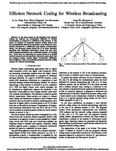
Fig. 1. Link model: PD stands for ”photo diode”, MF for ”matched filter”. The noise source (n) has a two-sided power spectral density PSfrag replacements b represents the discrete time signal component. Ψnn (f ) = N0 /2. The term X ∈ {0, X} same must hold for Sb and ψ(t − iT ). In the following, the elementary waveform is assumed to be a unit energy2 Nyquist pulse: Z ∞ 0 for τ = iT, i 6= 0 ψ(t)ψ(t − τ ) dt = , (2) 1 for τ = 0 −∞
ψ(t) q
2 system-theoretic
energy an incoherent RF-detector is considered instead, which may also exhibit a quadratic detection characteristic, the noise source is located in front of the nonlinear device and not at the output. This leads to a totally different conclusion. 3 If
1 T
0
where T denotes the binary symbol interval. Transmission takes place under the constraint of a fixed avere ψ(x) age optical power P . If the probability of a transmitted symbol Sb (corresponding to a binary ”1”) is denoted as p1 , P is given by √ Z Z ∞ R∞ 2 2 1 1 (t) dt = 1 ptx (t) dt = p1 Sb ψ(t) −∞ dt . ψ (3) P = lim Ti →∞ Ti T i T −∞
Note that p1 = 0.5 always maximizes the entropy at the channel input. However, since we assume intensity modulation and direct detection, p1 = 0.5 does not necessarily maximize the mutual information under the fixed average power assumption. The receiver consists of a photodiode with sensitivity R, a matched filter having the impulse response ψ(−t), and a sampling circuit. In the considered binary case, the undisturbed signal amplitudes X at the sampling times iT can be either zero or b = RS, b which can be expressed as a function of P and T as X follows √ b = RSb = T · R R · P (4) X ∞ e p1 ψ(x) dx −∞ √ e with x = t/T and ψ(x) = T ψ(x · T ) . √ b in fact depends on T , we have introduced a To show that X e normalized version ψ(x) of the waveform ψ(t) in (4). The dimenR∞ e e dx sionless function ψ(x) and the corresponding integral −∞ ψ(x) are effectively a measure of the waveform shape — independent from the actual symbol duration T , as illustrated in Fig. 2. b depends Eqn. (4) shows that the system-theoretic power of X on the square of the transmitted or received optical power. However, the noise source n(t) in Fig. 1 is located at the output of the photodiode, thus it is the photocurrent itself which exhibits an additional Gaussian distributed, zero-mean white noise component3 . It is beyond the scope of this article to discuss the origins of n(t) or the validity of the assumption that the noise power spectral density is really white (see e.g. [6, 7]), but it should be noted that n(t) is typically fully independent from the signal prx (t); instead, the noise power density is mainly determined by the amount of the
ψ(t) q
2 T
T 2
T
e dx = ψ(x) −∞
1 √ 2
R∞ 0
1 2
t
0
e ψ(x)
R∞
−∞
1
1 x
T 2
0
T
t
e dx = 1 ψ(x) 1 2
1 x
Fig. 2. Two examples for applicable waveforms. The RZ-impulse √ with 50% duty cycle on the left hand side achieves a 2 power advantage compared to the NRZ-pulse on the right hand side, if all the other parameters are fixed.
received background light and the thermal/transistor-noise of the first input stage. If the two-sided power spectral density Ψnn (f ) of n(t) is Ψnn (f ) = N0 /2, then the discrete-time noise component N of the discrete-time received signal Y = X + N is statistically described by Z ∞ N0 N ∝ N (0, N0 /2), since . (5) N0 /2 · ψ 2 (t) dt = 2 −∞ 3. THE REFERENCE: UNCODED OOK To derive the coding gain limits in the next section, the required optical power P = Pref of uncoded OOK-transmission guaranteeing a certain bit error probability pe will be used as a reference. Taking ψ(t) as a unit energy base function, the Euclidian distance dEucl between the two possible values of X depicted in the b Supposing p1 = 0.5 (one dimensional) signal space is equal to X. as well as uncoded transmission, the bit error probability of OOK is therefore ! „ « b 1 1 dEucl X 1 1 ·√ ·√ pe = erfc = erfc . (6) 2 2 2 2 N0 N0 From (6) we can at first deduce an OOK reference value √ bref = 2 N0 · erfc−1 (2pe ), X
(7)
H(X;Y) [Bit/Symbol]
which depends on the required value of pe . Using (4) and setting T = Tb , this value corresponds to R∞ e dx r N ψ(x) 0 Pref = −∞ · · erfc−1 (2pe ) , (8) R Tb
where 1/Tb is the bit rate being equal to the symbol rate 1/T if no coding is applied. Although the primary focus of (8) is to act as a reference, this equation gives useful insights in different parameter dependencies PSfrag replacements for both coded and uncoded transmission: 1. If the bit-rate 1/Tb is increased by one decade, and all the other parameters√ remain fixed, the required power increases only by a factor 10 corresponding to 5 dB and not by 10 dB as in the case of a linear channel. 2. Assuming the transmission of a large number N of bits (a ”packet”), the √ required optical energy N Tb Pref decreases by a factor 10 if the data rate is increased by a factor 10. 3. Even if a distortion-less channel is considered, the required average power depends on the pulse shape — quite in contrast to linear channels. Furthermore, replacing √ ψ(t) by an a-times ”shorter” unit energy version ψ2 (t) = a · ψ(at) R∞ R e dx = √a ∞ ψe2 (x) dx, which is results in −∞ ψ(x) −∞ √ equivalently a factor a power advantage compared to the original situation — supposing that the first Nyquist-criteria is still satisfied. In other words: every factor 2 reduction of the pulse width reduces the required power by 1.5 dB, Fig. 2 shows an example. Throughout the paper we define the code rate Rc as the ratio between the actual binary symbol interval T and Tb : Rc =
T . Tb
(9)
1
√G Rc
0.9
=1
0.8
√G Rc
0.7
=
√
0.6
2 · 4.15
0.5 0.4 0.3
√G Rc
0.2
=
√
2 · 8.3
0.1 0
0
0.1
0.2
0.3
0.4
0.5
0.6
0.7
0.8
0.9
1
probability p1
Fig. 3. Mutual information as a function of the impulse density p1 . Since the Euclidian distance dEucl increases steadily with 1/p1 , all H(X; Y ) curves, for low p1 values, match asymptotically the input entropy curve H(X) = −p1 log2 (p1 ) − (1 − p1 ) log2 (1 − p1 ). is the irrelevance due to the Gaussian noise N described in (5). In the binary transmission case considered here, the probability density function fY (y) of the random variable Y , required to calculate H(Y ), is given as ! « „ b 2 1 − p1 p1 y2 (y − X) fY (y) = √ +√ ·exp − ·exp − , N0 N0 πN0 πN0 b is already defined in (11). where X √ Fig. 3 shows H(X; Y ) for different quotients (G/ Rc ) as a √ function of p1 . Obviously, if (G/ Rc ) > 1, the maximum mutual information is not obtained for p1 = 0.5.
The coding gain G Pref (10) P is defined as the ratio between the OOK-reference power Pref and the actual required average optical power P to assure a certain bit error probability pe . In (10), the parameters N0 , Tb , R as well as e the pulse shape ψ(x) are supposed to be fixed. Using (10), X can also written as a function of G and Rc : „√ « 0.5 Rc b=X bref · X · . (11) G p1 G=
4. CODED OOK TRANSMISSION
4.1. Mutual information for OOK Taking X and Y as the random variables at the channel’s input and (soft) output, respectively, the mutual information H(X; Y ) is given as H(X; Y ) = H(Y ) − H(Y |X) , (12)
where the differential entropy of Y is Z ∞ H(Y ) = fY (y) log2 fY (y) dy, −∞
and H(Y |X) = 0.5 · log 2 (πeN0 )
4.2. Capacity and coding gain To calculate the maximum gains attainable with OOK-transmission, H(X; Y ) has to be maximized over p1 . If the (very small) influence of the ”allowed” bit error probability pe on the required capacity is neglected, the capacity C per binary symbol C = max H(X; Y )
(13)
p1
!
must be as high as the code rate Rc , i.e., C = Rc . To study the achievable coding gains, we have chosen pe = 1 · 10−9 for the uncoded OOK-reference. The solid line in Fig. 4 shows the coding gain G in dB as a function of the code rate Rc . The pulse density p1 was optimized numerically. Fig. 5 shows the corresponding pulse densities p1 (solid line). As depicted in Fig. 3 already, a code rate Rc = 0.5 promises a coding gain of 9.2 dB; this gain requires a pulse density of about p1 = 1/7. If the code rate is further decreased to Rc = 0.1, on one hand a gain of as much as 15 dB is attainable, but on the other hand this gain is traded with a very low pulse density, which is close to p1 = 1/57. Low pulse densities may cause several problems: obviously, the optical peak power Pb = P/p1 increases by a factor 1 Pb = 2G · p1 Pbref
0
10
35 30
10⋅log (G) [dB] 10 10⋅log (G)+5⋅log (R ) [dB] 10
10
pulse density p
1
25 coding gain [dB]
p1(1/Rc) p1(1/H(X))
−1
10
c
20 15
−2
10
−3
10
−4
10
10
5 0
0 0 10
1
10 1
10
2
10 1/R
3
10
2
3
10 10 10 1/Rc (solid line) or 1/H(X) (broken line)
4
10
4
10
c
Fig. 4. Coding gain as a function of the code rate Rc for OOK with optimized pulse density p1 . The interrupted line shows the residual gain, if the always available ”shaping gain” −5 log 10 (Rc ) [dB] is subtracted. compered to the optical peak power Pbref = 2Pref of uncoded OOK. However, as the calculation for code rates Rc > 1/10 shows, the possible gain in regard to the average optical power over-compensates the peak power enhancement due to the reduced pulse density. Other problems associated with low p1 values may be the more complicated symbol synchronization at the receiver or, as a result of the significant amount of low frequency signal components, a performance degradation due to interferences caused by artificial light [6]. The dashed line in Fig. 5 shows, that p1 can be well approximated or ”predicted”, if the input entropy H(X) is considered.
Fig. 5. Pulse density p1 over the code rate Rc (solid line). For comparison, p1 is also displayed over the input entropy H(X). code provides only a very small additional gain. This may lead to the conclusion that the slope of G over Rc asymptotically reaches a value of 5 dB per decade. Actually, as shown below this is not √ true at all, since G · Rc grows unbounded — even though very slowly. It is a fact that the average required electrical energy per bit (el) Eb of the photo diode current irx (t) (see Fig. 1) asymptotically reaches a certain fixed value if Rc is decreased steadily. For this (el) (el) case, we denote the fixed ratio between Eb and N0 as η∞ : (el)
Eb for Rc → 0 . (14) N0 The electrical energy at the sampling device can also be expressed using the optical quantities: (el) η∞ =
(el)
Eb
4.3. Asymptotic behavior To allow a discussion on the asymptotic behavior, the code rate is varied over 4 decades in Fig. 4. In contrast to linear channels, the coding gain grows unbounded with 1/Rc . This is not surprising, since in section 3. it was already derived that a reduction of√the pulse width by a factor a corresponds to a power advantage of a. This ”shaping gain” is also available in the digital domain. If, for example, the code rate Rc is reduced by a factor a simply by attaching a number of (a − 1) zero-symbols to every original symbol si , which leads automatically to a factor a reduction of p1 , the same Euclidian √distance dEucl between the symbols as before is achieved with a less optical power, see (11). Hence, the situation at the receiver remains completely unchanged if the zero-symbols attached at the transmitter are discarded at the receiver. Consequently, to appraise the effectiveness of the coding, the gain G attainable p should be weighed with the ”trivial” shaping gain, which is 1/Rc , to extract the effective gain contributed by the distance-properties of the actual code. This is shown additionally in Fig. 3. It can be seen, that the gain G for Rc = 0.1 lies 10 dB over the nominal shaping gain of 5 dB. However, if the code rate is further decreased by 3 decades, the additional gain compared to the 15 dB shaping gain is only 2.5 dB — the actual
=
b 2 p1 X . Rc
(15)
Using (7) and (11) it follows for Rc → 0 that „ «2 2 bref X erfc−1 (2pe ) 0.52 1 (el) , = · · = η∞ N0 p1 · G2 p1 G
(16)
resulting in a gain
1 erfc−1 (2pe ) G= √ · q p1 (el) η∞
for
Rc → 0 .
(17)
As expected, at very low values of Rc a factor 10 reduction of p1 corresponds to a 5 dB increase of G. Furthermore, a gain is only available if p1 is steadily reduced with Rc . Empirically one would argue that, having already very low p1 values, a further reduction of p1 requires the same reduction of Rc . However, as indicated in the left diagram of Fig. 3, H(X) and Rc exhibit the same slope over p1 . Since H(X) ≈ −p1 log2 (p1 ) for p1 → 0, it follows that p √ G · Rc ∼ − log2 (p1 ) for Rc → 0 . (18)
In other words: even at very low coding rates, the gain over Rc is slightly larger than 5 dB per decade, but most of the gain available is simply due to the ”shortened” pulses.
5. CODING GAIN FOR PULSE-POSITION MODULATION PPM is a very popular modulation scheme for wireless optical transmission. First of all, orthogonal PPM provides a power gain compared to the OOK-reference — even without additional coding. Furthermore, for small numbers M of PPM-symbols used, the transmitted signal contains much less low frequency spectral components than uncoded OOK, which is preferable for wireless optical transmission [6]. 5.1. Transmission model for PPM
∀i
Depending on the i-th M -level symbol si , si ∈ {0, 1, . . . , M −1}, one out of M orthonormal signals φj (t − iTPPM ) is chosen and transmitted. Orthogonality is achieved by placing the pulse ψ(t) defined in (2) at one of M distinct positions jT j = 0, 1, . . . , M − 1.
(21)
where T is usually denoted as chip interval in the case of PPM. With p1 = 1/M , the average optical power is already defined in (3). The receiver consists of M different filters ψj (−t) whose outputs are sampled at t = iTPPM and used to estimate the transmitted signal. If the M sampled filter-outputs are treated as vectors, the received discrete-time signal vector Y is given as Y =X +N ,
(22)
where X ∈ {x0 , x1 , . . . , xM −1 } is the signal component and N b defined in (11), the signal vectors is the noise component. With X are given as follows: b 0 . . . 0]T , . . . , xM −1 = [0 . . . 0 X] bT . x0 = [ X
where the term in the brackets comprises the symbol error to bit error ratio. Therefore, PPM without additional ”outer” coding achieves a gain of r r erfc−1 (2pe ) M log2 (M ) M log2 (M ) ` e´ G≥ ≈ . (27) 2 2 erfc−1 4p M
With Rc = T /Tb , the requirement for the mutual information H(X; Y ) per PPM-symbol is now !
H(X; Y ) = H(Y ) − H(Y |X) = Rc · M.
(23)
The noise vector N has M i.i.d. noise components statistically described in (5). 5.2. Uncoded PPM We still treat Rc = T /Tb as the coding rate. Consequently, even if no additional coding is applied to the PPM-symbols, the code rate is log2 (M ) Rc = . (24) M This makes sense, because PPM can be also considered as a linear code combined with OOK, where each of the M code words consists of M binary symbols. Using this definition of Rc , we can interpret 1/Rc as a direct measure of the required bandwidth. Taking φj (t), j ∈ {0, 1, . . . , M − 1}, as a set of M orthonormal base functions, the Euclidian distance between signal vectors xi is r √ b =X bref · M log2 (M ) 1 , dEucl = 2 · X (25) 2 G
(28)
Since the conditional probability
fY |X (y|xi ) =
(20)
The PPM-symbol duration TPPM and the original binary symbol interval T are related as follows: TPPM = M · T,
(26)
5.3. Coded PPM
To discuss the coding gain limits for M -PPM, the proposed OOKmodel has to be extended first. The transmitted signal is now X b s (t − iTPPM ) . Sφ (19) ptx (t) = i
φj (t) = ψ(t − jT ),
for the uncoded case. This yields an upper bound of « „ « „ dEucl M M −1 √ · erfc , · pe ≤ 2 2(M − 1) 2 N0
·
M Y j=1
j6=i
„
1 πN0
«M/2
« „ yj2 , exp − N0
0 “
b yi − X B exp @− N0
”2 1
C A·
∀i ∈ {0, 1, . . . , M − 1}
(29)
is equal to the joint probability of the corresponding noise vector n = y − xi , the irrelevance (supposing PPM symbols with equal probability) is now H(Y |X) = H(Y |xi ) = 0.5 · M · log 2 (πeN0 ) ∀i.
(30)
Similarly, the entropy H(Y ) at the output is Z fY (y) log2 fY (y) dy = log 2 (M )− H(Y ) = − y Z M X fY |X (y|xj ) dy . (31) fY |X (y|xi ) log2 y j=1 Since it is impossible (at least impractical) to solve the M dimensional integral in (31), we used Monte-Carlo simulations to obtain H(Y ) — as suggested in [8]. We first generated a large number (106 ) of random vectors y according to the conditional probability function p(y|x1 ). Then the logarithm in (31) was calculated for all the y-vectors and averaged over the total number of random vectors. 5.4. Results Fig. 6 shows the coding gains attainable with M -PPM. It should be noted that, as a result of our definitions, a value Rc = log2 (M )/M corresponds to uncoded PPM-transmission. The associated gains derived in (27) can be easily acquired by means of the origins of the curves marked with a ”x”. Uncoded 4-PPM achieves a 3 dB gain compared to our OOK-reference, 16-PPM a 7.3 dB gain. These values lie approximately 6 and 4.5 dB, respectively, below the theoretical limit for binary transmission (dashed line). If PPM is combined with an additional ”outer” code, the gains clearly converge for Rc → 0 to fixed values, since the probability of the logical ”1” pulses p1 remains fixed for each M -value.
15 M=16 M=8
10 coding gain G
M=4
M=2
5
0 0 10
1
10 1/Rc
2
10
Fig. 6. Coding gain as a function of the code rate Rc for M PPM and ”equal probability OOK” with p1 = 0.5 (dashed-dotted line). The code rate of the ”outer” code combined with PPM is only Rc · M/ log2 (M ). These gain-limits can be easily calculated with (17) if the individ(el) (el) ual electrical η∞ values are known. For 2-PPM, η∞ it can be 4 derived to be exactly 3 dB above the well known minimum elec(el) (el) trical Eb /N0 -ratio of log(2). The same η∞ holds for ”equal probability OOK” which is also displayed in Fig. 6. If M is in(el) (el) creased, η∞ comes closer and closer to log(2). If η∞ = log(2) is inserted in (17) in conjunction with p1 = 1/M = 1/16, the gain limit would be 13.1 dB which is very close to the asymptotical value depicted for 16-PPM. Fig. 6 shows a further detail in conjunction with coded PPM. At distinct code rates Rc and large M ’s, the gain comes very close to the maximum value attainable for ideal binary transmission (dashed curve). Where the gap is about 5 dB for coded 2PPM, it is clearly less than 1 dB for M = 16. This shows that MPPM with it’s spectral advantages can indeed be advantageously combined with coding for optical transmission. Furthermore, in the ideal case, the code rate of the additional outer code could be quite small. 6. CONCLUSIONS In the article we derive the maximum coding gain attainable with binary transmission, under the assumptions of a fixed average optical power and additive white Gaussian noise. We first developed an OOK transmission model and discussed the uncoded OOK reference scheme. Useful insights in the special characteristics of the 4 For
linear channels, antipodal transmission combined with ideal cod(el) ing achieves the minimum electrical Eb /N0 value of log(2) for Rc → 0. In the signal space, ”equal probability OOK” is equivalently with antipodal transmission if the OOK-DC component, being 3 dB below the overall electrical OOK-power, is eliminated. The situation for 2-PPM is similar. In the electrical domain, the two ”logical” pulses ”1 0” and ”0 1” can be replaced by ”+1 -1” and ”+1 +1” (Walsh-sequences) while the orthogonality is still assured. However, the first ”+1” is completely redundant from the information theoretic point of view and wastes 3 dB.
considered quadratic type of channel where obtained. We have shown that the required optical power does not increase linearly with the bit rate, but in fact with its square root. Furthermore, in the opposite to linear channels, the required power depends also on the pulse shape. We have introduced a normalized version of the waveform (representing logical ones), whose integral effectively measures the influence of the pulse shape on the required power. For a fixed symbol rate√it was shown, that the required power can be reduced by a factor a if the pulse width is reduced by a factor a. The maximum coding gains for optimized OOK transmission where derived. A coding rate of 1/2 promises theoretically a gain of 9.2 dB, a code rate of 1/10 a gain of 15 dB. In contrast to linear channels, the code gain grows unbounded. However, at code rates smaller than 1/10, the gain is dominated by the ”shaping gain”, which is always available if the code rate and with it the pulse density are reduced. If, for example, the code rate is reduced from 1/10 to /1000, the additional gain attainable with optimized OOK is about 17.5 dB, which is only 2.5 dB more than the nominal ”shaping gain” of 15 dB. In the final section orthogonal PPM was introduced, which ensures specific spectral characteristics. It was shown, that at specific code rates the gains available with coded PPM come close to the limits for binary transmission — supposing a relatively large number of PPM-symbols. 7. REFERENCES [1] M. Wolf and D. Kreß, “Short-Range Wireless Infrared Transmission: The Link Budget Compared to RF,” IEEE Wireless Communications Magazine, , no. 2, pp. 8–14, Apr. 2003, Online: http://ieeexplore.ieee.org. [2] Fritz R. Gfeller and Urs Bapst, “Wireless In-House Data Communication via Diffuse Infrared Radiation,” in Proc. of the IEEE, 1979, vol. 67, No. 11, pp. 1474–1486. [3] J.M. Kahn and J.R. Barry, “Wireless Infrared Communications,” Proc. of the IEEE, pp. 265–298, Feb. 1997. [4] D. Wisely and I. Neild, “A 100 Mbit/s Tracked Optical Telepoint,” in Proc. of the 8th IEEE International Symposium on Personal Indoor and Mobile Radio Communications (PIMRC’97), Helsinki, 1997, vol. 1/3, pp. 964–968. [5] R. You and J. M. Kahn, “Upper-Bounding the Capacity of Optical IM/DD Channels With Multiple-Subcarrier Modulation and Fixed Bias Using Trigonometric Moment Space Method,” IEEE Trans. On Information Theory, vol. 48, no. 2, pp. 514– 523, Feb. 2002. [6] A.C. Boucouvalas, “Indoor ambient light noise and its effect on wireless optical links,” in IEE Proc.-Optoelectron., Dec. 1996, vol. 143, pp. 334–338. [7] G. W. Marsh and J. M. Kahn, “50 Mb/s Diffuse Infrared FreeSpace Link using On-Off Keying with Decision-Feedback Equalization,” in Proc. of PIMRC’94/WCN, 1994, pp. 1086– 1089. [8] S. Dolinar, D. Divsalar, J. Hamkins, and F. Pollara, “Capacity of Pulse-Position Modulation (PPM) on Gaussian and Webb Channels,” Tech. Rep., TMO Progress Report 42-142, Aug. 2000.