The University of New South Wales. Sydney ... machine learning applied on an autonomous robot in an ... members by learning shared characteristics that could be visual ..... Computer Society Conference on Computer Vision and Pattern.
A Relational Approach to Plane-based Object Categorization Reza Farid, Claude Sammut School of Computer Science and Engineering The University of New South Wales Sydney, NSW 2052 Australia {rezaf,claude}@cse.unsw.edu.au Abstract- Inductive Logic Programming (ILP) is used in this paper to learn classifiers for generic object recognition from range images. These images are converted to point clouds that are segmented based on planar surfaces. Each set of planes that may represent an object is labelled and used for learning. The hypothesis is that a relational description for an object class can be built based on a set of defined features to make robust object categorization. The robustness of the result is evaluated by 10-fold cross validation on a set of images related to urban search and rescue. The results show the capability of producing highly accurate classifier by using ILP for objects encountered by a robot in an urban search and rescue environment. Keywords- range image, point cloud, range camera, object classification, urban search and rescue, machine learning, inductive logic programming, ALEPH, cross validation, Microsoft Kinect
I.
INTRODUCTION
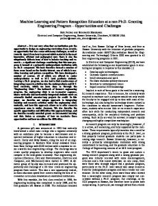
The aim of this work is to classifying objects by using machine learning applied on an autonomous robot in an urban search and rescue operation. The inputs are 3D range images, each taken as partial view of an environment. To be able to categorize objects, a representation for object classes and a method for classification are required. The classifier recognises class members by learning shared characteristics that could be visual, structural, functional, etc. 3D depth cameras such as the Microsoft Xbox Kinect provide both range and video images; while their cost is much less compared with the previous generation of such cameras. As a result, they are now becoming widely used. Each pixel in a range image, represents the distance of the sensor to the surface of an object in a scene from a specific viewpoint [1, 2]. The range image provides information that can be used to infer the shape of the object [3]. The Kinect, also provides a colour video camera; however we only use the depth information for object recognition in this paper because the colour calibration could make problem under different lighting conditions [4]. A set of 3D coordinates, or a point cloud, can be produced using a range image. In Figure 1 a range image of a staircase is shown. It has four steps while taken by a robot positioned in front of the staircase. The figure also includes two front and top views for the same
point cloud. The plane-based segmentation has been applied to the point cloud; which planes are identified by unique colours. Since the image is taken from one viewpoint, it only shows a partial view of the scene. Multiple views are required to construct a complete 3D point cloud for an object. However in this paper, we do not need the complete 3D point cloud of the object. In this work, the result of segmentation is represented by planes. After extracting planes from the 3D point cloud; they are used as primitives for object recognition. In many built environments, including urban search and rescue for identifying floors, walls, staircases, ramps and other terrain that the robot is likely to encounter, planes are suitable. Next step is using an ILP system to discover how planes and their relationships form an object class. The paper is structured as follows: first, we briefly review related work. We then, describe the approach. Finally, the utility of this approach is demonstrated in the experimental results. II.
RELATED WORK
Generic object recognition (also known as object categorization) has been an interest to a considerable amount of researches lately [4, 5]. It is required by robots in many tasks. For example in service robotics applications, such as a catering or a domestic robot [6], the robot must recognise specific kinds of tableware. In industrial applications, the robot has to distinguish a set of products [7]. Generally, object recognition systems use two approaches: global and local. In the former, the global features are used to determine if an object is present in the image. For example, a colour histogram can be used to represent how an object‟s colour is distributed in the image. Global features as in the Gaussian image [8] and related spherical representations [9] can be used to determine the pose of objects. In contrast, in local methods, local features, such as surface curvature [10] are used [11, 12] to describe objects. In generic object recognition (GOR) [13], a learning system is trained on instances of object classes to build class description that can be used for recognising unseen object instances [14] by understanding the scenes and creating categories [4, 15].
There are two major steps in object categorization: a learning phase, where the system is trained on instances of each class, and the detection or recognition phase, where the classification happens [11]. Generally, most recognition methods do not work on raw data. Instead, they map the data to a feature space at first. In other words, recognition methods extract local or global features that can be used to describe the object or the part of the object where that feature is extracted. Next step is using the features for classification [7]. Some features can be extracted after segmenting the 3D point cloud obtained from a range camera. While some methods [16-18] use planes as primitives, Rusu et al. suggest an approach in [19] which segments and reconstructs an object model by fitting planes, spheres, cylinders and cones as primitives. A survey of these methods is given in [20, 21] and a recent overview is presented by Vaskevicius in [22]. There is another method introduced by Triebel et al. in [23] which he uses associative Markov network for labelling the point cloud and segmenting it. The most recent method is by Bo et al. in [24] which uses a range of local features and creates five kernel descriptors that encodes features which are useful for recognition such as size, shape and edges. After extracting of primitive shapes, the next step is to create a mechanism to categorize objects. Using one or more visual cues for breaking down the object has been studied in recent methods for the object classification [25]. Pechuk et al. proposed a scheme in [26] which describes object classes as functional components by relating segmented parts. For example, a chair can be represented by functional sub-parts such as „sittable‟, „back support‟ and „ground support‟. To describe an object in this scheme, a multi-level hierarchy of functionalities is created. This hierarchy shows how functionalities and sub-functional parts can be formed using primitives such as stick, plates and blobs. The input data are labelled for training using this representation. This method focuses on positive examples and uses radial-basis functions in learning. Nüchter et al. suggest an approach in [16] for labelling the planes and using a constraint network to interpret the scene based on labelled objects and their relationship. This method uses Prolog to build the network solver. For classification, two approaches are introduced in this paper. The first one considers using 2D rendering of distance data with a Support Vector Machine for classification. The second approach uses AdaBoost on extracted features. Shin et al. propose a framework in [27] which works on part-based representation for the object while the relation between its parts is modelled by random variables to create a probabilistic geometric grammar for each object category. By parsing of extracted primitives, the classification can be done. Finally, learning process can be considered as representing the shared characteristics of an object class by set of rules as Burnside ES et al. show in [28]. Our segmentation method is a region growing algorithm that uses a point‟s normal vector. We use planes as primitives and we follow Nüchter et al [16] and
Burnside ES et al. [28] in using a clausal representation with introducing new set of features. The most recent and closest method to ours is by Holz et al. [18] which uses range images produced by a Microsoft Xbox Kinect. However that work focuses on obstacle and object detection. Here, we emphasize using relational learning for object categorization based on our new features. III.
THE APPROACH
We use the plane as a primitive for object categorization, where an object is considered to be a set of planes. To form the planes, point‟s normal vector is calculated and used to segment the point cloud. Attributes of the planes that form the object are used to represent the object. The attributes include the spherical representation of the planes normal vector. Attributes also include the relationships between pairs of planes, such as the angle between two adjacent planes. After extracting the features, plane-sets are labelled according to the class to which they belong. An Inductive Logic Programming system (ILP) [29] builds a classifier for each class, where objects belonging to that class are considered positive examples and all other objects can be treated as negative examples. We use ILP because it is capable of learning relationships between object features and is not limited to a simple feature vector representation of object features. Also, the result of learning is more readable and easier to analyse in comparison to other machine learning methods. Moreover, relational representations can be used to accumulate knowledge since learned concepts can become background knowledge for later training. As a result, the system can build complex hierarchical representations of concepts such as a staircase, which can be described as a set of steps, where the concept of “step” has been learned previously. A. Plane Fitting The first step is applying a region growing algorithm to segment range data into a set of planes. Although there are some methods for plane fitting, such as the one described by B. Rusu in [30], we used our own method, which integrates with our existing Rescue platform. To do so, the range image is converted to a point cloud. In contrast to other point cloud representations, the points in our point cloud are aligned in a grid and, then, it is easy and fast to find eight neighbouring points (P2, P3, …,P9) for each point P1 in counter-clockwise order [31]. For each point P1, eight triangles P1PiPj (P1P2P3, P1P3P4, …,P1P8P9 and P1P9P2) can be created and for each triangle, one normal vector is set by calculating the cross product P1Pi and P1Pj (Figure 2) [32]. By averaging these eight normal vectors, and normalizing the result, the normal vector for point P1 is found. Finally, smoothing is applied to each normal vector by averaging over the neighbourhood of each point to reduce the effect of noise in the normal vector calculation. The neighbourhood window size used for this experiment is 2. In other words, if Pi has coordinates (x,y) in the range image, a window size of 2 covers 25 points around (x,y) which are in the coordinate range (x±2,y±2).
After calculating the normal vectors, the region growing algorithm (Algorithm 1) is used to fit planes to the point cloud. In this algorithm, we start with an empty set, called R here, to keep the regions. We also scan points in the range image‟s grid structure. One unvisited point is chosen from the grid in any iteration and is checked against criteria described below. If the result is unsatisfactory, the point is ignored. Otherwise, it is tagged as visited and added to the current region while all of its neighbours are added to the list of candidate points for next iterations. The next candidate point is chosen until no more points remain in the candidate points list. This indicates that the region cannot be expanded further. The current region is added to region set R. As mentioned, we define criteria to decide adding a point to a region. First criterion is if the point has not been visited before. The second is that the angle between the point‟s normal vector and a normal vector representing the current region, called base_ normal, is less than a threshold. We have used an empirically derived threshold value of 15°. When the number of points in the current region is less than a minimum value (which is at least 8 neighbours around the first point) or is a multiple of this number, the base_ normal is updated by averaging the normal vector of all region points. These threshold and parameter values are mostly intuitive but further testing can be done to set them dynamically. The planes shown in Figure 1, result from this algorithm. The normal vector of the plane is calculated by averaging the normal vectors of all points forming that plane.
B. Feature Extraction Some of the attributes used for learning describe properties of an individual plane. One such attribute is the spherical representation of the plane‟s normal vector (θ and φ)[32] as shown in Figure 3. Note that θ is defined as zero when x is zero in order to avoid undefined value. Other attributes are derived from the convex hull of the plane. These are the diameter and width of the convex hull and the ratio between these values. To calculate the attributes of the convex hull, we modified the minimumarea bounding box algorithm provided in Geometric Tools [33]. The next set of attributes describes the length of the plane along the axes using the plane‟s bounding cube with respect to the sensor‟s frame coordinates. One attribute specifies the axis along which the plane is distributed. Three other features are the ratios of these distributions two by two. Figure 4 shows the results of segmentation, convex hulls creation and normal vector representation for a scene that contains a pitch/roll ramp and maze wall objects. These are elements that have been proposed by the US National Institute of Standards and Technology (NIST) [34] as standard features of a rescue robot validation course. They are also used in the RoboCup Rescue Robot competition [35]. Another feature is based on the relationship between each pair of planes, i.e. the angle between the normal vectors of each pair. Algorithm 1 – region growing using normal vector 1. 2. 3. 4. 5. 6. 7. 8. 9. 10. 11. 12. 13. 14. 15. 16. 17. 18. 19.
R={} For p[i] in all points If p [i] is visited then continue Cregion=p[i] // current region points Base_normal=p[i].nv // normal vector p[i] is visited candidates=loadNotVisitedNeighbours(p[i]) For all p[j] in candidates { If (Cregion.Size()