Comparison of two methods for the finite element analysis of nonlinear 3D periodic eddy-current problems René Plasser1, Yasuhito Takahashi2, Gergely Koczka3 and Oszkár Bíró1, Member, IEEE 1
2
IGTE, Graz University of Technology, 8010 Graz, Austria,
[email protected] Department of Electrical Engineering, Doshisha University, Kyoto 6010-0321, Japan,
[email protected] 3 Transformers Weiz, Siemens Inc. Austria, 8160 Weiz, Austria,
[email protected]
Two different techniques for the analysis of nonlinear, periodic eddy-current problems are compared using a 3-dimensional benchmark problem. The methods are the parallel time periodic-finite element method and the harmonic balance fixed-point technique. Index Terms —Eddy currents, nonlinear magnetics, finite element analysis, computational electromagnetics
I. INTRODUCTION
T
HE TOPIC OF this investigation is to validate various methods for the finite element analysis of nonlinear, 3dimensional eddy-current problems in which steady state solutions are of interest. For this reason a basic single phase transformer enclosed by a steel tank has been modeled. On each limb of the core there is half of the primary and secondary winding. To be as close to a practical application as possible, the transformer primary winding is voltage driven. Due to the highly permeable materials of the transformer one has to deal with a nonlinear problem. The occurring timevarying magnetic field induces eddy-currents in the tank walls and hence additional losses. In this work the parallel time periodic-finite element method (parallel TPFEM) [1], [2] and the harmonic balance fixed-point technique (HBFP) [3]-[6] are compared.
II. FEM FORMULATION AND MODELLING
T1 0 C1 T2 0 C 2 0 0
0
0
C n 1
C n 0 x1 G1 0 xn Gn Tn
(3)
and
A. Parallel Time-Periodic Finite-Element Method In case of the parallel TPFEM method, applying Galerkin techniques to the differential equations resulting from the A-V formulation, one obtains a system of nonlinear ordinary differential equations: d S ( x) C x f . (1) dt The matrix S is nonlinear due to its dependence on the unknown vector x and hence on µ, C is a constant coefficient matrix, f is the right-hand-side vector. By considering time periodic conditions xi xi n , all the nonlinear equations for one or half period are written as
1 S ( x1 ) t C ( x1 xn ) f1 S( x ) 1 C( x x ) f 2 2 1 2 , t S( x ) 1 C ( x x ) f n n n 1 n t
where n is the number of time steps in a (half) period, Δt is the time interval, the subscript indicates the time step, and the signs − and + in (2) correspond to the ordinary and half timeperiodic conditions, respectively. In the parallel TPFEM [1], [2], the large nonlinear system of equations (2) is solved by using parallel computing with pure message passing interface (MPI) programming. Adopting the Newton-Raphson (NR) method as a nonlinear iteration method, the linearized equations of the TPFEM can be written as
(2)
S ( xi ) C C Ti Si , Ci , Si (4) t t x where xi is the increment of xi and Gi is the residual. For solving the nonsymmetric linear system (3), we adopt the BiCGstab2 method and the localized ILU preconditioning. B. Harmonic Balance Fixed-Point Method In case of the harmonic balance fixed-point method [3], [4], applying Galerkin techniques to the differential equations resulting from the T , formulation, one obtains a system of nonlinear, ordinary differential equations of the form d S ( ) x C ( ) x f . (5) dt S depends on the resistivity ρ and is hence independent of x and time t. The mass matrix C depends on the permeability μ and hence on x and t. The vector x gathers the unknowns, f is the right hand side vector. Using the HBFP technique [5], the equation system becomes
S jmC(FP(s) ) Xm(s1) Fm jmC FP(s) (s) x(s) f ,
(6)
(s) whhere FP is thhe fixed-poinnt reluctivity at a the s-th iteeration steep and Fm ddenotes the m-th harmonnic of the F Fourier traansform. Since the nonnlinearity is ddue to the dependence of C C(µ) on the solution, it is obvious to define a fieldd independent fixedpooint permeabiility µFP. Hennce, one has to solve the given eqquation system m in each iterattion step s. Thhe voltage exccitation off the coils is im mplemented ass described in [7].
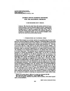
FE E-model paralleel TPFEM
FE-moddel HBFP
IIII. NUMERICA AL INVESTIGAT ATIONS To compare tthese two metthods, a singlee phase transfformer waas modelled as a benchmaark problem. The finite ellement m models of the ddifferent methoods should be as close as poossible to each other. Half of the primary andd of the secoondary wiinding are wound around each limb with w the two halves coonnected in seeries. In this aapproach the coils c are assum med to bee voltage driveen. The main parameters off the transform mer are given in TABLE I.
Fig. 2: Eighth of the trransformer modeel for the parallel TPFEM
F Fig. 2 and Figg. 3 show thhe finite elem ment mesh off the probblem domain. With the A-V V formulation used the coils are moddelled with finnite elements. With the T , formulaation the coils need nott to be includeed in the meshh. The nonlineearity ferent of tthe core and ttank material is consideredd by two diffe B-H H characteristiccs.
T TABLE I MAIN PARAMETERS OF THE TRANSFO ORMER Values Voltage Urmms Current Irmss Resistance R No. of turns N Frequency f
Unit V A 1 Hz
Priimary winding 6600 3.03 21.7 1886
Secondary windiing 210 95.2 0.0163 60 550
Fig. 3: Eighth off the transformer model for the HB BFP
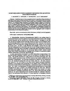
IV. NUMERIICAL RESULTSS F Fig. 4 shows the normalizeed deviation of the compputed currrents of the cooils when the coils c are voltagge driven.
T The parameterrs in the table are Urms for thhe root mean square vaalue of the exxcitation voltaage, Irms for thhe given currrent, R indicates the reesistance of thhe windings, N is the num mber of turns and f is thee operating freequency.
Fig. 4: Comparison off the calculated cuurrents of the coills.
F Further results will be presennted at the connference and inn the full paper. V. REFEERENCES [1]
[2]
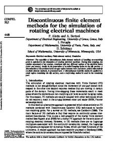
[3] Figg. 1. Basic transfoormer model.
Fig. 1 shows the basic transformer designn with the steeel tank suurrounding thee transformer.. If the excitaation of the ccoils is sinnusoidal, the resulting tim me varying maagnetic field ccauses edddy currents in the highlly permeable,, conductive metal hoousing and hennce additional losses. Thesee eddy-current losses arre to be investigated. Becauuse of symmetrry only an eigghth of the problem doomain is to bbe included inn the finite ellement model. m
[4] [5] [6] [7]
Y. Takahashi, T. T Iwashita, H. N Nakashima, T. Tookumasu, M. Fujiita, S. Wakao, K. Fujiiwara, and Y. Ishhihara, “Parallel Time-Periodic F FiniteElement Methodd for Steady-Statee Analysis of Rotaating Machines,” IEEE Trans. Magn., V Vol. 48, No. 2, pp. 1019-1022, Feb. 2012. Y. Takahashi, T. T Tokumasu, M. Fujita, T. Iwashhita, H. Nakashim ma, S. Wakao, and K. F Fujiwara, “Time-D Domain Parallel Finite-Element F M Method for Fast Magnettic Field Analysiss of Induction Mootors,” IEEE Tranns. On Magn., Vol. 49, No. 5, pp. 2413-22416, May 2013. MethS. Ausserhofer, O. Bíró, K. Preis “An efficient Haarmonic Balance M od for nonlinear eddy current problems”, IEE EE Trans. On Magn., M Vol. 43, No. 4, ppp. 1229-1232, (22007). G. Koczka, O. B Bíró, “Fixed-poinnt method for solvving nonlinear peeriodic eddy current prroblems with T, F-F formulation”, COMPEL, Vool. 29, No. 6, pp 1444-1452, (2010) Ausserhofer, O. B Bíró, K. Preis “O Optimal convergennce of G. Koczka, S. A the Fixed-Point Method for Nonnlinear Eddy Currrent Problems”, IEEE Trans. On Magnn., Vol. 45, No. 3, pp. 948-951, (20000). E. Dlala, A. Bellahcen, A. Arkkioo, “A fast fixed-pooint method for soolving magnetic field pproblems in mediaa of hysteresis”, IIEEE Trans. On M Magn., Vol. 44, No. 6, ppp. 1214-1217, (22008). O.Biro, K. Preiss, G. Buchgraber, I. Ticar, “Voltagee-driven coils in ffiniteelement formulaations using a currrent vector and a magnetic scalar potenp tial” IEEE Transs. On Magn., Vol.. 40, No. 2, pp. 12286-1289, (2004)