Computer Arithmetic Structures for Quantum Cellular Automata K. Walus, G. A. Jullien, V. S. Dimitrov University of Calgary/Electrical and Computer Engineering, Calgary, Canada
[email protected]
Abstract— In this paper, we discuss arithmetic structures based on quantum cellular automata (QCA). By taking advantage of the unique capabilities of QCA we are able to design interesting computational architectures. We describe important design considerations and show how addition and multiplication circuits can be implemented using QCADesigner, a QCA design tool which has been developed in our laboratory. QCA technology allows, among other things, the implementation of majority boolean gates and interconnecting “wires” that support cross-overs on the same fabrication level. One of the important challenges with QCA design is working within a different cost function from standard transistor circuits. These differences arise from the device level latching inherent in QCA. This latching makes the total delay of a circuit directly proportional to the maximum number of clocking zones between input and output and the number of gates.
I. I NTRODUCTION Quantum cellular automata (QCA) is an emerging nanotechnology that has been gaining attention in the research community because of its interesting features, simple concept, and potential for real world applications in the near future. QCA is generally rated in the top six of promising emerging technologies, and has been shown to be capable of general computation through the interaction of single charges within cells consisting of several nanostructure quantum dots. The reader is directed to [1]–[4] for a complete introduction to this paradigm as many of the fundamental concepts are not reviewed in this paper. Although QCA is still in the research stages, some experimental devices have been created as a proof of concept [5]–[7]. Research efforts are also underway to determine the fault-tolerance of such devices [8]. In many ways, QCA circuit can be directly translated from conventional designs with the addition of the special clocking structures. This provides engineers with a relatively easy transition from working with transistor technologies to designing with QCA. Our vision for this technology is that it will be an important part of a multi-technology foray into the fabrication of future high performance computing systems. A multi-technology approach will allow the best of the various current proposals for nano computing technology along with the advancements in conventional FET-based technologies. Applications where low power, high speed, and high density are crucial is where QCA technology will prove its utility. QCA technology itself is not complete, it requires supporting technologies to enable a final useful implementation. Some of those supporting technologies provide clocking for QCA, some provide the ability to write/read information to QCA input/outputs. A QCA cell is
not able to drive the I/O pins required to interface to external circuitry; we require advanced transistor technologies to fill this gap. It is therefore not appropriate to talk about QCA as a complete replacement of existing technologies but rather as another weapon in our arsenal. We believe that arithmetic structures are an area that can take advantage of the full potential of QCA technologies. To date, several arithmetic and support circuits have been designed and simulated using tools such as QCADesigner [9]. These include adders [10], barrel shifters [10], basic FPGA’s [11], and RAM [12]–[14]. These circuits take advantage of the theoretical capabilities of QCA, such as coplanar wire crossing, which allows complete planar circuits to be designed without the need for metal layer interconnects. II. QCAD ESIGNER QCADesigner is the first publicly available design and simulation tool for QCA. Developed at the ATIPS Laboratory, at the University of Calgary, QCADesigner currently supports three different simulation engines, and many of the CAD features required for complex circuit design. Quantum mechanical simulations of QCA are performed using the timeindependent Schr¨odinger equation under the approximation that intercellular interactions are electrostatically coupled and wavefunction overlap between cells is nonexistent. This approximation excludes the coherence between neighboring cells in order to facilitate simulation of large circuits in reasonable time. Modeling a completely coherent QCA system would become prohibitive for designs, even with very few cells, because of the exponential growth in the state space of the system. For example, if we assume that the QCA cell can be represented by two basis states, then the size of the problem is O(2n ), where n is the number of cells in the design. Presently, the quantum mechanical simulation engine is based on a two-state approximation which assumes that the QCA cell can be modeled by two bases representing a fully polarized cell. This simulation is performed as follows: first the input vectors are applied to the corresponding input cells, setting the polarization of those cells to the input value. The simulation engine then iteratively calculates the polarization of every cell in the design until each cell has converged onto a polarization within a preset tolerance. At this time, the polarization of the output cells is recorded and a new iteration begins.
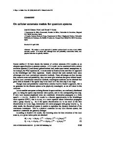
Fig. 2. QCA wire shown with cells and schematic representation. C0,C1,C2,C3 are the four phases of the clock. Each of the clocking zones maps to a latch in the circuit representation. Notice that only one clocking zone is latched. Fig. 1. The four available clock signals. Each signal is phase shifted by 90 degrees. When the clock signal is low the cells are latched. When the clock signal is high the cells are relaxed and have no polarization. In between the cells are either latching or relaxing when the clock is decreasing/increasing respectively.
Because a final realization of QCA has not yet been determined, the speed performance of the cells are assumed to be completely determined by the QCA clock (discussed in the next section). As a result, we assume that the evolution of the cell state is adiabatic; i.e., the state of the system remains very close to the ground state throughout the simulation. III. QCA C LOCKING AND D EVICE L EVEL L ATCHING Unlike the transistor, QCA basic cell has no inherent directionality for information flow, and a circuit made of unclocked cells would propagate information in uncontrollable directions. It has been shown that signals traveling along arrays of QCA cells can be reflected off imperfections and interfaces analogous to reflections from impedance mismatches in RF circuits. In order to control the flow of information in a QCA circuit, four clock signals, each shifted in phase by 90 degrees, as shown in Figure 1, are used [15], [16]. These clock signals are expected to be generated by a supporting technology such as a CMOS circuit. Another important difference is that QCA cells themselves do not exhibit any power gain; the clock is required to provide the cells with the power gain to transmit signals along lengthy QCA wires. The clock signals act to pump information in the circuit as a result of the successive latching and unlatching in cells connected to different clock phases. For example, a wire, which is clocked from left to right with increasing clocking zones, will carry information in the same direction; i.e., from left to right. This acts to pipeline QCA circuits at a device level. QCA wires are unique in that more then one bit of information can be propagated along the same wire at any one time. A low value of the clock means that the cells are latched. When the clock signal is high, the cells are relaxed, and have no polarization. In between, the cells are either latching or relaxing when the clock is decreasing/increasing respectively. The minimum size of the clocking zone is determined by the minimum feature size of the technology used to support clocking. Large clocking zones can be problematic because signals traveling down long QCA wires have increased probability of error from outside influences. These include thermal effects, which can potentially flip the state of a cell. Small clocking zones allow the designer the ability to create more complicated
Fig. 3. A clocked QCA majority gate. The addition of the majority gate does not increase the latency of the wire compared to that without a majority gate.
and dense circuits. They also decrease the probability of error in the circuit. The trade off is that electromagnetic problems may arise when trying to fabricate small and irregular patterns for the clocking structures. IV. D ESIGN C ONSIDERATIONS QCA is a technology that is pipelined at a device level; the interconnects themselves are made of self latching cells, controlled by the QCA clock. Each group of cells connected to a particular phase of the clock can be considered as a D-latch. A length of QCA wire can be represented schematically as shown in Figure 2. This inherent device latching has a major effect on the design cost function. The different clocking zones in Figure 2 are represented with different shades of gray. An important consequence of this device level clock structure is that, if we replace a section of the wire with a majority gate, we find that the delay of the wire and a gate is the same as a wire without the gate. This is shown in shown in Figure 4, where the majority gate is created by the five cells arranged in a cross pattern and connected to the same clocking zone. This layout can be represented schematically by including a D-latch for each clocking zone. The latch representing the Majority gate is shown directly at its output. The schematic for the Majority gate input and output wires is shown in Figure 4. These considerations force us to evaluate our designs differently than we would if we were designing with traditional technologies. Even in heavily pipelined transistor based logic architectures, there will normally be many gates in a combinational structure between each latch in the pipeline. In QCA, the latency is determined completely by the largest
Fig. 4. Schematic representation of the majority circuit. We introduce a D-latch for each clocking zone in the QCA circuit.
number of clocking zones between input and output, with each gate and wire connection being connected to a clocking zone. The original concept of QCA, as a quantum level implementation of classical cellular automata (CA), is evident from the inherent clocked operation at the device level. Although CA architectures are not normally implemented in most synchronous digital systems, we can look at structures that have similar properties as being target candidates for QCA implementation. Examples are bit-serial architectures and systolic arrays. Interestingly, parallel designs, which require large fan-outs to the parallel logic components, will introduce more latency because of the very nature of QCA interconnects. Another important consideration is that designs based on majority gates will be most suitable for implementation using QCA. This is because the majority gate and inverter are the only fundamental logic elements available with QCA. Other gates are created using a combination of these two gates. The challenge of working with QCA circuits is first finding the best representation of the desired function. An important challenge for designers is finding an algorithmic method for reducing boolean logic, based on the usual set of primitives, to majority gate logic. V. QCA A DDITION The addition operation is an example where majority logic can reduce the overall number of gates required to create the full-adder [17]. The majority gate schematic for a full adder is shown in Figure 5; the schematic includes the Dlatches representing the clocking zones in the circuit. It is important to ensure that each input to a majority gate arrives simultaneously. This is guaranteed by placing all inputs to a majority gate on the same clocking zone. Also, the Sum and Carry should arrive at the output simultaneously, this is done by making the number of clocking zones for the Sum and Carry circuits equal to each other. The layout for this adder was created using QCADesigner and is shown in Figure 6. The schematic was created to match the layout. Note that the number of clocking zones (represented in different shades of gray) is equal for both the Sum and the Carry. This design can be used to create a bit-serial adder by simply feeding the carry back into the adder. Interestingly, and contrary to traditional technologies, the bit serial adder has the same latency as a ripple-carry adder. This is a result of the inherent latency in the interconnects which dominates the timing of the system. As a result, there is no advantage
Fig. 5.
Adder schematic using only majority gates.
Fig. 6.
QCA cell layout of adder.
to creating a parallel adder using QCA because the parallel adder would take up significantly more area without any delay advantages. The layout for the bit-serial adder is shown in Figure 7. VI. QCA M ULTIPLICATION In this section, we describe the design of a bit-serial/parallel multiplier circuit using the adder created in the previous section. The design is based on a multiplier schematic created for conventional FET-based logic circuits, and is shown in Figure 8. The D-latches in this schematic are required for the proper operation of the device and are not QCA zone latches. In order to transfer this design into a QCA circuit, we have to realize that many more D-latches are introduced from the very nature of a QCA circuit. With this in mind we can generate a schematic for a QCA multiplier and introduce the required Dlatches appropriately so as to maintain proper circuit operation. With this design one of the inputs is broadcast across the adder serially and the other is loaded in parallel. The partial products are calculated and immediately added to the sum. The schematic for this multiplier is shown in Figure 9. The Dlatches represent each of the clocking zones in the circuit and are numbered accordingly. The delay for this 2-bit multiplier
Fig. 10.
Layout of QCA bit-serial multiplier.
grows linearly with the number of bits, making it efficient in area. As the size of the multiplier is increased, the delay from input to output also increases linearly. VII. QCA I MPLEMENTATIONS Fig. 7.
QCA cell layout of bit-serial adder.
Fig. 8. Schematic of bit-serial multiplier, assuming traditional technologies.
is 3 clock cycles, where a clock cycle is represented by the four clocking zones. The QCA layout for the 2-bit multiplier is shown in Figure 10. The schematic is drawn to match the layout as much as possible. Although there is a delay between the signal entering the multiplier and the first bit at the output, there is no latency introduced between the output bits. As well, because of the pipelined nature of QCA, a new multiplication can start before the previous one is completed. The bit-serial/parallel multiplier can easily be scaled by adding more full-adder blocks and partial product generators in a continuous array. We have experimented with designs as large as 32-bit using this layout. The size of the multiplier
Fig. 9.
Schematic of QCA bit-serial multiplier.
The QCA concept is generic in that there may be several different implementation possibilities. At the core of the concept is a bi-stable cell, which must interact locally with its neighbors such that information processing can be performed as described previously. The cell is not required to remain quantum mechanically coherent throughout the computation, thereby opening the door for many non-quantum mechanical implementations of such a cell. As a result, several ideas have emerged to either test the QCA concept, or provide a path for a final realization of QCA technology. Of all the implementations, four distinct classes of implementation have clearly emerged. These are: • Metal-Island • Semiconductor • Molecular • Magnetic The metal-island implementation was created as a means of proving the QCA concept. It is based on the Coulomb blocking phenomena of nano-structures and was shows to exhibit the electron switching as required by a QCA cell [15]. The metalisland implementation does not have the structural properties for a scalable design, and, as a result, was only meant as a proof-of-concept implementation. In this scheme aluminum metal-islands are used to represent the quantum dots of a QCA cell. The metal-islands in the initial experiments are on the order of 1 µm in dimension, and therefore, the system had to be cooled to extremely low temperatures for the electron switching to be observable. Semiconductor implementations are advantageous in that they can potentially use the highly advanced and matured semiconductor fabrication processes. Presently semiconductor fabrication processes suffer because to date the fabrication processes have not yet reached a point where we can mass produce devices with features only a few nanometers in scale. To make small features possible serial lithographic techniques, such as electron beam lithography, are used, which are not currently suitable for mass production of devices. Semiconductor QCA technology uses nano-structure quantumdots to trap electrons [2]. The standard QCA cell used in the
design of the circuits described in this paper is based on the properties of a semiconductor implementation of QCA, where polarization is encoded in charge position and interactions are electrostatically coupled. There has been some research into the potential realization of an quantum computer using semiconductor QCA [18]. Presently, many researchers are investigating potential realization of QCA cells using single molecules [19]–[21]. The molecular implementation of QCA offers many inherent advantages including: highly symmetric cell structure; very high operating speeds; room-temperature operation; and very high device density. Although molecular QCA has many attractive features, there are still many challenges to be overcome before any molecular based computing technology is available for public use. Some of these challenges include: the selective placement of molecules on a surface, as well as; the realization of a mechanism for performing I/O operations with single molecules; determining which molecules are most suitable for QCA operation; design of a clocking technology that can provide the clocking zone granularity required for complex circuit design. Recently, magnetic QCA, or MQCA, has also gained some attention [22], [23]. MQCA is based on interacting magnetic nanoparticles. The magnetization vector of these nanoparticles is analogous to the polarization vector in electronic QCA and information is propagated via magnetic exchange interactions, as opposed to the electrostatic interactions in all other implementations. Although this technology is referred to as magnetic quantum cellular automata, the term quantum in this case represents the quantum mechanical nature of the exchange interaction and not electron tunneling, as in the electronic QCA. One of the immediate advantages of considering such a technology is that MQCA cells would operate at room temperature, even for large device features on the order of a few hundred nanometers. VIII. C ONCLUSION To conclude, we have discussed some of the important considerations that QCA designers have to keep in mind when evaluating particular algorithms for QCA arithmetic. We have shown that the cost function for QCA is completely different than that for traditional FET-based technologies because the number of clocking zones from input to output determines the total delay and not the number of gates. Using a design and layout tool developed at the ATIPS laboratory we have shown the construction of a full-adder using these considerations, and also modifications required to create an adder that can be used to build a bit-serial addition circuit. We have discussed the advantages of serial circuits over parallel circuits in QCA; the basic reason is the increased latency associated with the extra interconnects. Using the bit-serial adder we have also demonstrated that it is possible to design a bit-serial multiplier. This work has assumed that the theoretical capabilities of QCA will be realized in the final technology; otherwise, adjustments to the designs will have to be made. In order to provide a complete picture of this technology, we have described briefly
the potential implementation technologies for realizing QCA based circuits. ACKNOWLEDGMENT The authors acknowledge the financial support of research grants from the Natural Sciences and Engineering Research Council of Canada, Micronet R&D (a Network of Centres of Excellence), iCORE (Alberta), and workstations and tools from the Canadian Microelectronics Corporation. R EFERENCES [1] C. S. Lent, P. D. Tougaw, “A device architecture for computing with quantum dots”, Proc. IEEE, vol. 85, no. 4, pp. 541-557, 1997. [2] W. Porod, “Quantum-dot devices and quantum-dot cellular automata”, Inter. J. Bifurcation and Chaos, vol. 7, no. 10 pp. 2199-2218, 1997. [3] P. D. Tougaw, C. S. Lent, “Logical devices implemented using quantum cellular automata”, J. Appl. Phys., vol. 75, no. 3, pp. 1818-1825, 1994. [4] I. Amlani et al., “Digital logic using quantum-dot cellular automata”, Science, vol. 284, pp. 289-291, 1999. [5] I. Amlani et al., “Experimental demonstration of a leadless quantum-dot cellular automata cell”, Appl. Phys. Lett., vol. 77, no. 5, pp. 738-740, 2000. [6] A. Orlov et al., “Experimental demonstration of clocked single-electron switching in quantum-dot cellular automata”, Appl. Phys. Lett., vol. 77, no. 2, pp. 295-297, 2000. [7] A. Orlov et al., “Experimental demonstration of a binary wire for quantum-dot cellular automata”, Appl. Phys. Lett., vol. 74, no. 19, pp. 2875-2877, 1999. [8] T. J. Dysart and P. M. Kogge, “Strategy and prototype tool for doing faultmodeling in a nano-technology”, 3rd IEEE Conference on Nanotechnology, 2003. [9] K. Walus “ATIPS laboratory QCADesigner homepage”, http://www.atips.ca/projects/qcadesigner, ATIPS Laboratory, University of Calgary, Canada, 2002. [10] A. Vetteth, et al., “Quantum dot cellular automata carry-look-ahead adder and barrel shifter”, IEEE Emerging Telecommunications Technologies Conference, 2002. [11] M. T. Niemier, A. F. Rodrigues, P. M. Kogge “A Potentially Implementable FPGA for Quantum Dot Cellular Automata”, 1st Workshop on Non-Silicon Computation (NSC-1), Boston, MS. 2002. [12] A. Vetteth, et al., “RAM design using quantum-dot cellular automata”, 2003 Nanotechnology Conference, vol. 2, pp. 160-163, 2003. [13] D. Berzon, T. J Fountain, “A Memory Design in QCAs using the SQUARES Formulism”, Technical Report, University Collage London, UK, 1998. [14] S. Frost, A. F. Rodrigues, A. W. Janiszewski, R. T. Raush, P. M. Kogge, “Memory in motion: A study of storage structures in QCA”, First Workshop on Non-Silicon Computing, 2002. [15] G. T´oth and C. S. Lent, “Quasiadiabatic switching for metal-island quantum-dot cellular automata”, J. Appl. Phys., vol. 85, no. 5, pp. 29772984, 1999. [16] K. Hennessy and C. S. Lent, “Clocking of molecular quantum-dot cellular automata”, J. Vac. Sci. Technol. B., vol. 19, no. 5, pp. 1752-1755, 2001. [17] W. Wang, K. Walus, G. A. Jullien, “Quantum-Dot Cellular Automata Adders”, IEEE Nano 2003 Conference, San Francisco, CA. 2003. [18] G. T´oth, C. S. Lent, “Quantum computing with quantum-dot cellular automata”, Phys. Rev. A, vol. 63, pp. 1-9. 2000. [19] C. S. Lent, B. Isaksen, M. Lieberman, “Molecular Quantum-Dot Cellular Automata”, J. Am. Chem. Soc., vol. 125, pp. 1056-1063, 2003. [20] C. S. Lent, “Molecular Electronics: Bypassing the Transistor Paradigm”, Science, vol. 288, pp. 1597-1599, 2000. [21] C. S. Lent, B. Isaksen, “Clocked Molecular Quantum-Dot Cellular Automata”, IEEE Trans. Electron Devices, vol. 50, no. 9, pp. 1890-1895, 2003. [22] R. P. Cowburn, M. E. Welland, “Room Temperature Magnetic Quantum Cellular Automata”, Science, vol. 287, pp. 1466-1468, 2000. [23] M. C. B. Parish, “Modelling of Physical Constraints on Bistable Magnetic Quantum Cellular Automata”, Ph.D. Thesis, University of London, UK, 2003.