COMSOL Multiphysics is used to simulate the displacement sensitivity of the accelerometer along X and Y directions. Solid Mechanics (solid) physics.
COMSOL Simulation of a Dual-axis MEMS Accelerometer with T-shape Beams Ce Zheng1, Xingguo Xiong2, Junling Hu3, 1 Department of Electrical Engineering, University of Bridgeport, Bridgeport, CT, USA 2 Department of Electrical and Computer Engineering, University of Bridgeport, Bridgeport, CT, USA 3 Department of Mechanical Engineering, University of Bridgeport, Bridgeport, CT, USA Abstract: Inertial navigation in 3D space requires acceleration measurement along all three degree-offreedoms. For improved efficiency, accelerometers which can sense acceleration along multiple axes are desired. In this paper, a dual-axis MEMS (Microelectromechanical Systems) accelerometer with T-shape beam structure is proposed. When there is acceleration input along X and Y directions, the Tshape beams bend accordingly due to inertial force. The bending displacement along X and Y directions can be measured by differential capacitance sensing, hence the input accelerations can be derived. COMSOL Multiphysics is used to simulate the displacement sensitivity of the accelerometer along X and Y directions. Solid Mechanics (solid) physics and Electromechanics (emi) physics are used in device modeling. Stress intensity simulation of the device under input acceleration of 50g is also performed. The designed dual-axis MEMS accelerometer can be further integrated with a Z-axis accelerometer for complete 3D inertial navigation. Keywords: COMSOL multiphysics, Microelectromechancial Systems (MEMS), Dual-axis accelerometer, Differential capacitive sensing, Inertial navigation system.
1. Introduction Due to their small size, light weight, low cost and low energy consumption, MEMS (Microelectromechanical Systems) accelerometers have been widely used in smart phones, automobile, toys, aerospace and many other applications [1]. Most MEMS accelerometers are designed to sense acceleration input along single direction. For complete inertial navigation in 3D space, measurement of acceleration inputs along all three directions (X, Y and Z) is required. Hybrid integration of three single-axis accelerometers aligned along each direction is a straight-forward solution. However, it requires precise alignment and calibration of three separate accelerometers, which can be very challenging. A more efficient solution is to design accelerometer which can measure
acceleration along multiple axes. Various dual-axis MEMS accelerometers have been reported [2]-[6]. In [2], a MEMS dual-axis capacitive accelerometer with pendulum-proof-mass, a gimbal-spring and verticalcombs sensing electrodes is proposed. In [3], a dualaxis accelerometer with a single inertial mass symmetrically suspended by four pairs of folded elastic beams is reported. The four pairs of folded beams allow the movable mass to move along both X and Y directions due to inertial force. In [4], a highsensitivity dual-axis linear accelerometer is fabricated with CMOS-MEMS technology. In [5], a dual-axis MEMS inertial sensor that utilizes multi-layered electroplated gold for an arrayed CMOS-compatible MEMS accelerometer is reported. It allows both the signal sensing circuitry and the sensing units to be fabricated on the same chip. In [6], a dual-axis MEMS thermal accelerometer made with front-side bulk micromachining and CMOS technology is introduced. The accelerometer utilizes thermal convection phenomenon to sense the input acceleration. In this research, a MEMS dual-axis capacitive accelerometer with T-shape beams is proposed. It utilizes only two sets of T-shape beams to sense acceleration inputs along both X and Y direction in device plane. Each T-shape beam contains two folded beams and one straight beam. The T-shape structure allows the beams to bend along both X and Y directions due to input acceleration. The bending displacement of the beams is sensed by the differential capacitance change of the comb finger groups connected to the central movable mass. COMSOL Multiphysics is used to simulate the sensitivities of the accelerometer along X and Y directions. The contour plot of the stress intensity distribution for 50g acceleration input is also obtained. The proposed MEMS dual-axis accelerometer can be combined with a Z-axis accelerometer for complete 3D inertial navigation system.
2. Design and Analysis
Excerpt from the Proceedings of the 2015 COMSOL Conference in Boston
2.1 Strucctural Desig gn of Dual--axis Accelerom meter with T-shape Beams
MEMS S
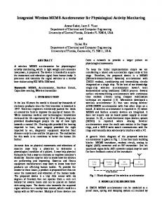
S The sttructure diagraam of the duaal-axis MEMS comb acceelerometer is sh hown in Figurre 1. It is to bee fabricated with polysiliccon surface-miicromachining. o T-shape beams connected to movablee It has two mass. The whole device is symmetric vertically and d hape beam co onsists of onee horizontallly. Each T-sh straight beam and 2 foldeed beams conn nected between n ntral mass. Th here are eightt the anchorr and the cen groups of movable fingers extruding from the fourr he movable maass. To simpliffy the analysis,, sides of th the two strraight beams an nd four vertical finger groupss are used to o sense acceleeration along X direction, so o they are called X-beamss and X-capaccitance groups. The four folded beams and four horrizontal fingerr groups arre used to seense accelerattion along Y direction, so they are called Y-beeams and Y-g capacitance groups. As shown in the figure, among ovable fingers, two groups off the four grroups of X-mo them havee fixed fingers in their left sides s and otherr two group ps have fixed fingers in theeir right sides. Together they t constitutee X-differentiaal capacitance. Similarly, among the four f groups of o Y-movablee wo groups of them have fix xed fingers in n fingers, tw their upper sides and other two grou ups have fixed d fingers in their down sid des. Together they t constitutee ning the fixed d Y-differential capacitancce. By design b only in one side of the mo ovable fingers,, fingers to be the interco onnects for left l and rightt (or top and d bottom) fix xed fingers wiill not cross eaach other. Thiss makes the fabrication pro ocess easier.
Figuree 1. Structure diagram of dual-ax xis MEMS accellerometer
The working w princip ple of the duaal-axis MEMS S acceleromeeter is explaiined as below w. If there iss acceleratio on input ax alo ong X directio on, the straightt
X-beeams bend due to inertial fforce, hence tthe Xdifferrential capacittance changes.. By measurinng this X-diffferential cappacitance chhanges, the input accelleration ax cann be calculatedd. On the otherr hand, if thhere is accelerration ay alonng Y direction, the foldeed Y-beams beend and Y-diff fferential capaccitance changges. By measuuring the Y-diffferential capaccitance changge, we know the input acceeleration ay. Table 1 show ws all the desiign parameterss of the devicee. The thickkness of polysillicon structure is set as t=4µm m. Tablee 1. Design Paraameters of MEM MS Acceleromeeter Com mponents Centtral mass Movvable fingeers Fixedd fingers Foldded beam ments segm Straiight beams Anchhors
Amoount 1 644 (8× ×8) 644 8 2 2
Length (µm) 800 400
Width (µm) 800 10
400 700
10 20
700 40
20 40
Nuumbers in figure 9 7 8 2,3,4,5 111,12,13,14 6,10 1,15
2.2 T Theoretical An nalysis MEMS acceleroometer with T-shape Thhe dual-axis M beam ms utilizes diff fferential capaccitance to sennse the displlacement of thhe movable m mass/fingers ddue to this device, thhe folded beam ms can inertiial force. In th only bend along Y direction, andd the straight beams can oonly bend aloong X directioon. This ensurres the crosss-axis couplingg effect of thhe acceleromeeter is minim mized. When there is no accceleration inpuut, the left ccapacitance gaap is equal to tthe right capaccitance gap (d1=d2=d0) fo for X-capacitaances, and thhe top capaccitance gap iss equal to the bottom capaccitance gap ((d3=d4=d0) forr Y-capacitancces. As a resuult, the left X-capacitancee equals to rright X-capaccitance C2=Cx0), and ttop Y-capacitannce equals to bbottom (C1=C Y-caapacitance (C3= =C4=Cy0). When there is accelerattion along X X-axis direcction, due to innertial force, the movable ffingers movee toward left bby displacement x, then: d1’’=d0-x, d2’=dd0+x, the X-cappacitance channge is 2 ∆ 2∆ ∙ (1) wherre Nx is the nuumber of X-diffferential capaccitance groupps, ε is permitttivity of air, S is the overlaap area betw ween a movablee finger and itss left (or right)) fixed fingeer (S=t×Lov, inn it t is the deviice thickness aand Lov is thhe overlap lenngth between movable and fixed fingeers), d0 is thhe static capaacitance gap of Xcapaccitance. Y-axis When there is accelerattion along Y direcction, assume movable finngers move ttoward bottoom by displaceement y due too inertial forcee. As a resullt, d3’=d0+y, d4’=d0-y, the Y-diffeerential capaccitance changee is
Excerpt from the Proceedings of the 2015 COMSOL Conference in Boston
∆
2∆ 2
2
∙
(2))
where Ny is i the number of Y-differentiial capacitancee groups, S is the overlaap area between a movablee ottom) fixed fiinger, d0 is thee finger and its top (or bo static capacitance gap of Y-capacitancee.
wherre E is the Y Young’s moddulus of the device mateerial (for polysiilicon, E=169G GPa [7]), wbx, tbx and Lbx aare the width, tthickness and llength of straigght Xbeam ms respectivelyy, wby, tby andd Lby are the width, thickkness and lengtth of folded Y Y-beams respecctively. Assuume uniform deevice thicknesss t, we have tbxx=tby=t. R Resonant frequuencies for vibrration along X and Y direcctions are: 3 (8) 2E w tbx 1 fx
2
Lbx
3
bbx wm Lm tm 64 w f L f t f
(9)
3
fy
1 2
2 E wbby tby
Lby w L t 64 w L t wherre wm, Lm annd tm are the width, lengtth and thickkness of centraal mass, wf, Lf and tf are the width, lengtth and thickneess of movabble fingers. Acctually tm=tf= =t (device thicckness). T The displacem ment sensitivityy is defined aas the displlacement of the movablee fingers peer 1g accelleration inpuut (g is grravity acceleration, 1g=99.8m/s2) alonng sensitivee direction. The displlacement sensiitivities of the accelerometerr along X annd Y directions are: wm Lm tm 64 w f L f t f g Lbx 3 (10) Sddx 3 2 E wbx tbxx 3
m
Figure 2. Differential D capaccitance sensing for f acceleration alon ng X-axis
S dy Figure 3. Differential D capaacitance sensing for acceleration alon ng Y-axis
a analysis,, we can see th hat under smalll From above deflection approximation n (i.e. x