It is understandable that Computer Aided Software Engineering (CASE) tool is an .... Assumption 1 (Expert users in their own business works): All potential users ...
JOURNAL OF INFORMATION SCIENCE AND ENGINEERING 26, 2229-2247 (2010)
Context-Adaptive Approach for Automated Entity Relationship Modeling SANGWON LEE1, NAMGYU KIM2 AND SONGCHUN MOON1 1 Department of Management Engineering Korea Advanced Institute of Science and Technology Seoul 130-722, Korea 2 School of Management Information Systems Kookmin University Seoul 136-702, Korea
Even a smart data modeler may not be an expert in terms of job knowledge. Hence, the design of a database model is limited by the data modeler’s resolution and subjectivity. Because the data modeler transforms a domain user’s representations into a database model on the basis of arbitrary decisions, the data modeler may distort or lose information. The best way of designing a database is for a domain user to lay out a database, though this approach might impose a heavy modeling burden on the user. Many traditional automated design systems have failed to become widely used. We propose a new model, the association-based conceptual model (ABCM), for an ordinary field worker. The ABCM does not require a user to have expert knowledge to discriminate entities from attributes and relies solely on business descriptions to generate an appropriate ERD. We devise a context-adaptive approach to automate the creation of ERD, which means that ER modeling depends on the context of a business description. Accordingly, this approach performs modeling by analyzing contexts in a business description that the user creates and then utilizing associations among the various contexts. We introduce the scope of the proposed system and present the detailed logic of the system. Finally, we perform a case study to evaluate the devised system’s applicability to practical business fields. Keywords: database design automation, entity relationship model, conceptual database design, association rule mining, data mining
1. INTRODUCTION An excessive supply of data and its complexity are steadily overwhelming and embarrassing most of enterprises. And also, a large percentage of processes related to a large amount of data are so complex that it is not easy for enterprises to know how to manage vast amounts of data, how to analyze them, and how to design them. In fact, the majority of the applications developed in most enterprises avail nothing because of their poor database design. The challenge of every organization is hence to evolve quickly from using old mess data to building databases with efficiency. Since even a smart data modeler is not an expert on job knowledge, the database model would be designed to his/her resolution and subjectivity. The modeler goes so far as to say that she does not know what data is changed or what data is wrong. In data modeling, there are inconsistencies between requirement representation [15] of a domain user and requirement recognitions of a data modeler. Since the data modeler transforms a Received October 7, 2008; revised January 21, 2009; accepted March 30, 2009. Communicated by Tei-Wei Kuo.
2229
2230
SANGWON LEE, NAMGYU KIM AND SONGCHUN MOON
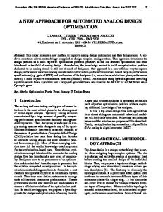
domain user’s representations into database model in arbitrary decisions, s/he could distort or lose information on business requirements. The best way for database design is that a domain user lays out his/her database for information systems, which could heavily impose a modeling burden on the user. Even domain users are of course experts about their working job, but they unprofessionally have no idea of database modeling. However, supposing that well-structured methodologies [1] or supporting systems for designing databases are developed, a domain user could satisfactorily take the place of a data modeler. In order that a domain user can design databases without a data modeler, sufficient and consistent description on the domain job for the enterprise-wide work [11] is necessary. Entity-Relationship Model (ERM or ER Model, for short) [4] is generally used to abstract business affairs into an integrated database schema [16]. The model uses a diagram, Entity-Relationship Diagram (ERD or ER Diagram, for short), and has major processes such as follows; finding out focal behaviors of the business applications, evaluating data objects from the viewpoint of the behaviors, and classifying the objects into entities or attributes. Since there are the cognitive distance [2] between field workers’ requirements and professional modelers’ perception, even an expert data modeler would fail to obtain an appropriate ERD without perfectly reflecting the original business affairs. To enable a field worker to perform data modeling without reliance on an expert modeler, Automated Database Design (ADD, for short) has introduced and deeply studied. Even though many traditional automated design systems [5-9, 12-14, 19, 23, 27] have tried to play an important role on behalf of the professional data modelers, they have not been used on a large scale. In the last few decades, those systems do not often give field workers sufficient practical support in formulating an adequate ERD. The first reason is that the systems are suited only for well-trained users with a good knowledge on data modeling. The second reason is that the task of putting business information into these systems requires too many interactions to users. The last reason comes from the staleness of their knowledge in the traditional knowledge-based systems. To suppose that the stale knowledge would be in accord with the present one is not in reason. Despite the fact that a data object should be classified flexibly into either an entity or an attribute according to the field worker’s various concerns, most traditional knowledge-based systems recommend that an object that happens to have been classified as an entity one or more times in the past applications should be entitized. Our object-classification will be progressed with judging from the existing state of things and without excessive reliance on prior knowledge about its object classification. Example 1 (Flexible Classification of an Object): Assume that a student belongs to a department, that a student has student_id and student_name, and that a department has department_id and department_name. Fig. 1 draws two cases of ERD on these assumptions. In order to manage a car owned by a student, it is sufficient for the Case A that the car is added as an attribute to a student. But, the Case B is also possible. In order to permit students to own plural cars or to manage the car characteristics (car_type, car_color), a car should be created as an entity with attributes (car_number, car_type, car_color), not as an attribute. That is to say, the object CAR can be flexibly classified as an attribute (Case A) or an entity (Case B) according to the various concerns of field workers. The schemata of Case A or Case B are as follows.
CONTEXT-ADAPTIVE APPROACH FOR AUTOMATED ENTITY RELATIONSHIP MODELING
dept_id dept_name
student_id student_name
DEPARTMENT
DEPARTMENT
BELONG TO
BELONG TO
STUDENT
STUDENT
car
2231
dept_id dept_name
student_id student_name
HAVE
car_number car_type car_color
CAR
Case A
Case B
Fig. 1. CAR as an entity or an attribute.
Schema of Case A DEPARTMENT: dept_id, dept_name STUDENT: student_id, student_name, car Schema of Case B DEPARTMENT: dept_id, dept_name STUDENT: student_id, student_name CAR: car_number, car_type, car_type On the contrary, if the real business environment is Case A, the entitization of CAR on the basis on the system’s stale knowledge would generate an absurd ERD which does not properly reflect the given business description. Generally, the traditional knowledgebased approaches do not consider the fact that even the same object could be regarded as either an entity in some cases or an attribute in the other cases according to the various concerns of field workers. To obtain an appropriate ERD for a specific application, we should extract entities or attributes on the basis of a given business description rather than system’s stale knowledge accumulated from past experiences.
Stage 1: Business Requirements
Stage 2: Conceptual Design
Stage 3: Logical Design
Stage 4: Physical Design
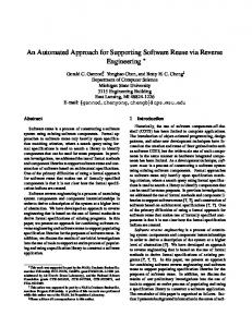
Fig. 2. The process of database modeling.
There have been many researches on the automation of database design for business requirements, but they were restricted to the logical design or physical one (Fig. 2). We will focus on the conceptual design. To collect ambiguous business requirements, we will use the business description. And to reduce the ambiguity of data modeling, we will
2232
SANGWON LEE, NAMGYU KIM AND SONGCHUN MOON
bring the automation. Although it is natural that to gather low information for database modeling generates some errors, its consistent procedure by the unit business [3, 18] should be performed. It should not be allowed to compromise with a data modeler, in the name of more rapid database design and even with accepting information distortion. To relieve errors consistently, we also need the automation for data base design. About business description, some people would believe that it is difficult and unrealistic to acquire it. However, we ceased these worries by several experiments of about ten and more enterprise-wide projects in the Republic of Korea. An instance is that, in only two weeks, we acquired the enterprise-wide business description of the Korea Broadcasting System (KBS) Company that has approximately 800 unit business processes with about 1600 employees. We had the employees write their own business description about the unit business processes in the first week, and integrated all the business descriptions hierarchically in the second week. This shows that it takes only several weeks to write the business description in a company, irrespective of the number of unit business processes or employees. This paper proposes a new methodology for extracting entity or attribute or relationship so that a field worker can perform the conceptual data modeling without an expert modeler. In extracting entities, this methodology uses only the business descriptions without any other information and generates an appropriate ERD. Before creating an ERD, a graphical tool called Association-Based Conceptual Model (ABCM or ABC Model, for short) is needed to find out associations between two or more objects described in the business descriptions. Even though the traditional Simple Binary Data Model (SBDM, for short) [4-7] can handle only two objects at once, ABCM can manage three or more objects as well as two ones in one breath. This ABCM covers the following algorithms; (1) refining rules for business descriptions, (2) detecting associations among objects extracted from the business descriptions, and (3) extracting entities, attributes, and relationships from the ABCM. This ABCM stands on the basis of the association rule [10] of data mining with confidence = 100. The remainder of this paper is organized as follows. We review related works in section 2. In section 3, we introduce the scope and detailed logics of the proposed system. And, in section 4, we perform a case study to evaluate the devised system’s applicability to practical business fields and section 5 finally concludes this paper.
2. RELATED WORKS It is understandable that Computer Aided Software Engineering (CASE) tool is an expedient for easily adopting too complicated development steps for information systems, but they could not give much help for field workers to perform conceptual data modeling. It is true that automation tools such as ERWin, Rational Rose, System Architect, or Power Designer save much time and endeavors for a professional modeler to draw ERDs and generate logical schemata from them. Though even ERWin, the most widely used tool in business fields, offers only a drawing function For ERD, it does not do a role to analyzing users’ requirements. To a CASE tool without requirement analysis may bring about passing over the original information and distorting it. Even though many previous studies on logical and physical phases have accom-
CONTEXT-ADAPTIVE APPROACH FOR AUTOMATED ENTITY RELATIONSHIP MODELING
2233
plished much contribution, few studies on the formal methodology for conceptual data modeling have been found in the literature. As a matter of course, there has been an approach [27] to formulate an ERD by use of data-intensive source codes. In the conceptual modeling, the greater parts of approaches have still begun their modeling process with analyzing users’ requirements. A most dominant approach [24] provided guidelines for extracting entity according to the principle of ERM theory. Two assertions on the basis of which most human database designers extract entities are as follows. One is that an object can be classified as an entity if it has descriptive information for itself. And the other is that, if a descriptor is multi-valued, the descriptor can be classified as an entity although it does not have any other descriptors. While [24] provided rather abstract guidelines for the entity extraction, [23] presented a statistical mechanism called Attribute Synthesis Method (ASM, for short). In finding out entities, ASM discovers objects from given tasks and then statistically manipulates the objects. During the statistical manipulation through several phases, ASM calculates values of three indices such as Usage Across Tasks (UAT, for short), Usage with Other Data (UOD, for short), and Usage Ratio (UR, for short). The indices help ASM to roughly choose entity candidates. If an object has higher UAT, higher UOD, and lower UR, there is an ample hope for being classified as an entity. But, since ASM does not define the thresholds for the indices clearly, it is ambiguous to determine whether a value of an index is high or low and then the users’ arbitrary selection of the threshold could make the quality of ERD uneven. There are many knowledge-based attempts [5, 6, 12, 14, 19] on automated conceptual modeling, which require a field worker to prepare lists of entities and attributes as initial inputs and then validate or refine them according to systems’ knowledge. Nowadays the advent of ontology-based conceptual modeling [20-22, 25, 26] renews the knowledge-based approaches. An approach [26] addressed four limitations in grammar of ERM by use of the ontology theory: construct deficit, construct overload, construct redundancy, and construct excess. The construct redundancy is especially based on the fact that a property construct of the real world could be represented as either an attribute or an entity in an ERD. A clear criterion for classifying property constructs or business objects into entities or attributes could resolve the construct redundancy. Since, in data modeling for to-be information systems, business descriptions play an important role to keep pace with business processes, they are worth being used. And abundant resources for data modeling could be systematically organized in them. An automated system with an appropriate Natural Language Processing (NLP) module [9] can accept a business description as an input and extract data objects and behaviors from the description. A recent research [8] shows an example to tie NLP into data modeling, which extracts conceptual dependencies from the whole sentences for a conceptual schema. Further studies on NLP could lesson the restrictions on writing business descriptions as inputs for design automation systems. Even though Requirements-driven Entity Extraction Methodology (REEM, for short) [13] is a good try to extract entities and attributes from business description in natural language, the algorithm for it is somewhat complex and loses the accuracy to extract entity and attribute. REEM, of course, transforms a business description into an ERD, but it does not accompany any objective and positive experiment. Above all things, REEM requires an additional process to refine a business description into a revised one. During
2234
SANGWON LEE, NAMGYU KIM AND SONGCHUN MOON
this process, REEM asks too many questions to a user, which drops convenience for the system. In addition, to require capitalizing all the objects in business description should get out of control for a user who has no knowledge about database. To impose no burden such as interaction with or capitalizing objects on a user, an automated tool extracting entity or attribute is in urgent need.
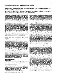
3. ASSOCIATION-BASED CONCEPTUAL SYSTEMS We devise context-adaptive approach to automate the creation of ERD, which means that ER modeling depends on context of business description. That is, this approach performs modeling by analyzing contexts in business description a user creates and then utilizing associations among contexts. Although there are many important issues relevant to ER modeling such as generalization, specialization, participation constraint, cardinality ratio, derived attributes, multi-valued attributes, entity types, and key constraints, this study focuses only on the most fundamental step of ER modeling; classifying entities or attributes from requirements. In this sense, this study could be a beginning step of automated database design. Our proposed ABCM is a model to automate conceptual data modeling and has a concrete and systematic structure, Association-Based Conceptual Systems (ABCS or ABC Systems, for short). Section 3.1 provides the general framework of ABCS with some assumptions, introduces each stage, and summarizes its output. In subsection 3.2, we explain concrete rules for our conceptual modeling in detail. That is to say, the subsection describes the whole process of using the user-written business description, extracting objects from the business description, drawing a relation (so-called subordination) diagram among objects, and finally completing an ERD. 3.1 Overall Architecture and Assumptions The designed system, ABCS is an automated tool for conceptual data modeling based on ABC Model (Fig. 3). The system is composed of Association-Based Conceptual Diagram (ABCD or ABC Diagram, for short) Generator and ERD Generator. The former with ABCD-related rules extracts objects and relations among objects from business description a field worker writes, and the latter with ERD-related objects then make an ERD on the basis of the result of the former. The overall process of ABCS is summarized as the followings; (1) a field worker freely writes a business description about his/her own business work in natural language. (2) BD (Business Description) Parser loads the business description on ABC Systems. BD Parser plays a role to extract objects in business description and registers them in Meta Dictionary. And it also parses the sentences with Meta Dictionary. (3) The business description is transformed into ABC Diagram by ABCD Generator. ABCD Generator extracts objects from the text-formatted business description and then automatically makes ABCD which clears up the relations among objects with ABCD-related rules. (4) ERD Generator translates ABCD Diagram into ER Diagram. (5) The field worker can get the ERD. Unlike Functional Dependency Diagram (FDD, for short) that manipulates the dependencies among only attributes, not entities, ABC Diagram handles relations among
CONTEXT-ADAPTIVE APPROACH FOR AUTOMATED ENTITY RELATIONSHIP MODELING
Stakeholder (Field Worker)
ABC Systems 1
5
2235
2 ABCD Generator
BD Parser Loader BD
Business Description
3
Meta Dictionary 4
ER Diagram
ERD Generator
ABC Diagram
Fig. 3. A life cycle of ABCS.
objects (attributes, entities, and relationships). Accordingly, the diagram can present the way to classify each object into entity or attribute. In drawing an ABC Diagram, ABCM Generator could discover a semantic redundancy and remove it whenever any relation among objects springs. While doing away with all semantically redundant relations from the initial ABCD, ABCD Generator consummates a more compact ABC Diagram. This revised ABC Diagram is transformed into an ERD. We will make mention of the internal logic for ABCD and ERD Generators in section 3.2. It is necessary above all things to propose several assumptions so as to define the environmental scope of the revised ABC Systems. The below Assumptions 1-3 should make the internal logic of the ABC Systems evident. Assumption 1 (Expert users in their own business works): All potential users must be well acquainted with their own works required by to-be application program. Although the final user would have no idea about database and do not know how to classify an object appeared in his/her own works into an entity or an attribute, he/she is assumed to be second to none about knowledge about his/her own works. Assumption 2 (Completeness of information): The business description a field worker makes should include all business behaviors related to business objects. All data object, that is, should be included in the business description without omission. Though this assumption would be unreasonable to the user, it is fairly possible since the user has the best knowledge about ones own works by the Assumption 1. What is more, this assumption does not require the user to remove any semantic redundant relation of objects. It is so because our system removes all the semantic redundancies by ABCD Generator. Out system requires demand not a compact business description without any redundant work but a complete one with fully described work. In addition, this business description is used for ERD Generator to create a relationship in transforming ABCD into ERD. Assumption 3 (Uniqueness and consistency of object’s name): For this assumption, ABCS operates Meta Dictionary that has all objects list. A field worker can describe objects of his/her own works with referring to Meta Dictionary. And then, ABCD Generator transforms the description into ABCD with referring to object list in Meta Dictionary. At this time, each object name should be unique and consistent through making the business description, which should not have any homonym or synonym about the object name.
2236
SANGWON LEE, NAMGYU KIM AND SONGCHUN MOON
The homonym or synonym must be removed since it would cause a semantic ambiguity of business rule. Namely, a unique name is forbidden to designate two or more objects and two or more names are banned to be assigned to the same concept concurrently. But the process to devise the module for homonym and synonym is excluded in this study. 3.2 Association-Based Conceptual Modeling Now we explain the internal rules for Association-Based Conceptual Modeling and we mobilize some examples for more detailed explanation. Subsection 3.2.1 introduces a business description. Subsection 3.2.2 defines some rules for extracting an ABC Diagram and subsection 3.2.3 does for extracting an ER Diagram. 3.2.1 Preparation for the business description It is truly easy for a company to prepare for the BD. A person, especially a data modeler in a department of Information Systems, would believe that it is difficult and unrealistic to acquire business description. However, in fact, it takes only several weeks to write the business description in a company, irrespective of the number of unit business processes or employees. While performing a project at KBS in the Republic of Korea, we acquired its enterprise-wide business description in only two weeks. 3.2.2 Extracting ABC diagram This ABCM refines rules for business descriptions, and detects associations among objects extracted from the business descriptions, and extracts entities, attributes, and relationships from the ABCM. All this procedure to extracting an ABC Diagram is absolutely based on the business description. Definitions 1-3 define sentence, object, and attribute, and refer to their notations. Definition 1 (Objects in each sentence): An object is a thing that has a fixed shape or form with a meaning. Instinctively, it is a candidate for entity or attribute in ER modeling. Meta Dictionary has information of all objects related to specific business. Let the business description be S. And assume that each sentence of S is S1, S2, S3, …, Sn. And then S has one or more objects. If a sentence Si has two objects, O1, O2, its expression is the following; for Si ∈ S, ∃O1, O2 ∈ Si. Definition 2 (Subordinations among objects): A subordination among objects is a kind of special relation among objects. Each object is expressed as a node, and a conjunctive link between objects is expressed by a subordination (→, ←, or ↔) between objects. A subordination O1 → O2 implies that an object O1 does not appear without an object O2. That is, O1 necessitates O2; for ∀Si ∈ S, ⌐∃Si s.t. O1 ∈ Si ^ O2 ∉ Si. O1 is subordinated to O2, where O1 is the subordinate and O2 is the subordinator. Meanwhile, in lieu of the subordination O1 → O2, O2 → O1 is generally represented for functional dependency [17]. Definition 3 (Notation of subordinations): Suppose that there are three objects, O1, O2, and O3, in a sentence Si. The subordinations among O1, O2, and O3 are summarized like
CONTEXT-ADAPTIVE APPROACH FOR AUTOMATED ENTITY RELATIONSHIP MODELING
2237
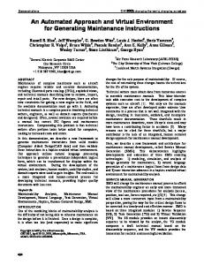
Fig. 4. Notation of subordinations.
Fig. 4. Notation N1 means the subordination between objects in Definition 2. Notation N2 is the subordination with both O1 ← O2 and O1 → O2. And notation N3 stands for the subordination with both O1 → O2 and O1 → O3. Now, by use of Definitions 1-3, we will draw an ABCD as the preprocessing phase for ERD. The following ABCD Rules 1-5 and Theorems 1-4 are the fundamental rules for automating the processes from BD to ABCD. ABCD Rule 1 (Mapping between BD and ABCD components): ABCD Components are composed of nodes and links. Each object in BD is represented as a node. But, for the object already mentioned in previous sentences, its node is not added. A subordination among objects is represented as a link. If O1 always appears with O2, the subordination is represented as O1 → O2. By Definitions 1 and 2, this procedure is accumulatively performed from BD sentence by sentence. ABCD Rule 1-1 (Grafting a subordination): Fig. 5 represents the grafting a subordination among O2 and O3. If there is an object O3 for an object O2, a subordination O2 → O3 is added. O1
O4
O2
O1
O4
Grafting O2 → O3
O2
O3
Fig. 5. Grafting a subordination in conceptual representation.
O1
O4
O2
O1
O3
Pruning O1 → O2
O4
O2
Fig. 6. Pruning a subordination in conceptual representation.
O3
SANGWON LEE, NAMGYU KIM AND SONGCHUN MOON
2238
ABCD Rule 1-2 (Pruning a subordination): In Fig. 5, there is initially a subordination O1 ↔ O2 between an object O1 and an object O2. This O1 ↔ O2 can be separated into O1 → O2 and O2 → O1 by N3 of Definition 3. If there is no mention of O2 in a sentence Si with O1, it means that there is not a subordination of O2 for O1. Hence, a subordination O1 → O2 is deleted from O1 ↔ O2 (Fig. 6). ABCD Rule 2 (Classifying into strong nodes or weak nodes): A node that has one or more outgoing link is defined as a weak node (W, for short). A node that has only income ing links and does have any outgoing link is also defined as a strong node (S, for short). This ABCD Rule 2 is applied en bloc to the outcome of ABCD Rule 1 (Fig. 7).
W
W
W
S
W
Fig. 7. A strong node and four weak nodes.
Now the following theorems are proposed for clarify the process to simplify ABCD. Theorem 1 (case 2).
If any W follows its links, it should meet S (case 1) or be located in a cycle
Proof: If an object is a weak node W, this node should have an outgoing link by ABCD Rule 2. On the assumption of W → A, (i) if A is a strong node, it surely meets S. On the other hand, (ii) if A is a weak node, it surely has an outgoing link by ABCD Rule 2. If this outgoing link points to other weak node that already appeared, A is cycled with other weak nodes. If it is not so, the process (i) or (ii) must be reiterated from the beginning. This repeating process would certainly let W meet S or be cycled with other weak nodes. W cannot come to an end as a weak node after following its links. Theorem 2 S cannot be located in a cycle. Proof: S means that it does not have any outgoing link by ABCD Rule 2. So, S cannot participate in formulating a cycle. ABCD Rule 3 (Creating a pseudo object): Let there be a cycle with three outgoing node, O1, O2, O3 (Fig. 8 (a)). A pseudo object (PO, for short) reflecting three subordinations O1 → PO, O2 → PO, O3 → PO should be added like Fig. 8 (b). If PO is not created, the nodes O1, O2, O3 could be orphaned without necessitating any object. PO should be a strong node. In Fig. 8 (c), PO is a strong node and O1, O2, O3 are weak nodes. Cycled objects are all W by Theorem 2. If a PO is added, this cycle is deleted. That is to say that the case (2) of Theorem 1 is removed and the case (1) remains. All O1, O2, O3 as W necessitates PO as S.
CONTEXT-ADAPTIVE APPROACH FOR AUTOMATED ENTITY RELATIONSHIP MODELING
O1
O1
O1
PO
PO
W
S W
O3
O2
(a)
O3
O2
2239
W O3
O2
(b) Fig. 8. Adding a pseudo object.
(c)
Theorem 3 After applying ABCD Rule 3, each weak node surely meets a strong node if following its links. Proof: If ABCD Rule 3 is applied, there should be any cycle no longer. By applying Theorem 1, any and every weak node comes to meet a strong node. ABCD Rule 4 (Simplification by transitivity): W1 → W2 → S is transformed into W1 → S and W2 → S. By Theorem 3, each W has an S as its host. This rule is the process to remove a link between weak nodes, that is, W1 → W2. The goal of this rule is for a child node (to-be attribute A) to find its parent node (to-be entity E). In W1 → W2 → S, W1 and W2 are mutually sibling and so the dependency W1 → W2 between them can be deleted, even though there would be information loss. In all of Cases 1-3 of Fig. 9, this ABCD Rule 4 simplifies each (a) into (b). Theorem 4
Every link that remains in ABCD is a relation, W → S.
Proof: There are four cases of links among W and S as follows; (i) W → S, (ii) S → W, (iii) S → S, (iv) W → W. Cases (ii) and (iii) run counter to the definition of strong node of ABCD Rule 2. Case (iv) is removed by ABCD Rule 3. After all, only the case (i), W → S, is affected. Case 1
W1
Case 2
W1
W2
S
W2
S1
W2
S
W2
S1
W3
S2
W1 S2
W3
W1
W1
W2
W4
W3
S2
S1
W1
W2
W4
W3
S2
Case 3
(a) Fig. 9. Simplification by transitivity.
(b)
S1
SANGWON LEE, NAMGYU KIM AND SONGCHUN MOON
2240
3.2.3 Extracting ER diagram ERD Rule 1 discriminates among entities and attributes. ERD Rules 2-5 decide the position for each attribute subordinate to entity or relationship. That is, ERD Rules 1-5 is used to simplify all associations among objects in the shape of A(attribute) → E(entity). ERD Rule 1 (Creating an entity or an attribute): In the extracted revised ABCD, every S is transformed into an entity and every W is transformed into an attribute. The fact that what attribute belongs to what entity is not important as yet, but the process to transform S or W into an entity or attribute is important. In Fig. 10, this rule converts W1 into A1, and does S1 into E1.
W1
A1
S1
E1
Fig. 10. Creating an entity and an attribute.
A2
E2
A2
E2
Fig. 11. Confirming an attribute of an entity.
E32
E31
A3
E31
R3
E32
A3
Fig. 12. Confirming an attribute of a relationship.
ERD Rule 2 (Confirming an attribute of an entity): If an attribute A has only one outgoing link and its indicated end is an entity E, A is an attribute of E. Fig. 11 shows that A2 is an attribute of E2. ERD Rule 3 (Confirming an attribute of a relationship): If an attribute A has two or more outgoing links and its indicated ends are E1, E2, …, En, a relationship R that participates in E1, E2, …, En is created and A is an descriptive attribute of R. At this time, the relationship R is named by use of the verb contained in a sentence that has E1, E2, …, En simultaneously. The information of verbs is handled by Meta Dictionary in Fig. 3. Meta Dictionary has information about object list, verb list with reference to business description. Simultaneous reference to A, E1, E2, …, En in a sentence means that A is an attribute of a relationship R among E1, E2, …, En. In Fig. 12, R3 is a relationship between E31 and E32, which has a descriptive attribute A3. ERD Rule 4 (Confirming a relationship without any attribute): First of all, it should be examined whether two or more entities appear for each sentence in BD, which a sentence, if any, should be chosen. For entity E1, E2, …, En that appear together in a sentence, if there is no relationship that is composed of E1, E2, …, Em, a relationship R is created by use of
CONTEXT-ADAPTIVE APPROACH FOR AUTOMATED ENTITY RELATIONSHIP MODELING
R4
E41
E42
E41
2241
E42
Fig. 13. Confirming a relationship with no attribute.
S2 E52
W
R5
E51
S3
S1
E53
A5
(a) (a)
S1
S2
S3
…
Sn
R6
E61
W1
W2
…
Wn
E63
E62
(b)
A61
A 62
E6n
…
A 6n
(b)
Fig. 14. Ternary or higher-degree relationship.
a verb in the sentence. Meanwhile, if there already is a relationship that is composed of E1, E2, …, Em, a relationship R is not added. In Fig. 13, a relationship R4 is created between E41 and E42 and its name of R4 is dubbed with referring to Meta Dictionary. ERD Rule 5 (Ternary or higher-degree relationship): If attributes A1, A2, …, An have two or more outgoing links and their indicated ends are E1, E2, …, En, a relationship R that participates in E1, E2, …, En is created and A1, A2, …, An are descriptive attributes of R. At this time, the relationship R is named by use of the verb contained in a sentence that has E1, E2, …, En simultaneously. The information of verbs is of course handled by Meta Dictionary in Fig. 3. Simultaneous reference to A1, A2, …, An, E1, E2, …, En in a sentence means that A1, A2, …, An are attributes of a relationship R among E1, E2, …, En. In Fig. 14 (a), R5 is a relationship between E51, E52, and E53, which has a descriptive attribute A5. Fig. 14 (b) is the generalization form of Fig. 14 (a). R6 is a relationship between E61, E62, …, E6n, which has descriptive attributes A61, A62, …, A6n.
4. CASE STUDY Section 3 showed theoretical bases and formulation of the methodology. It is however impossible to discover an absolutely answer that could correctly analyze or evaluate the methodological practicability. The reason is that a database schema is artistic and does not propose a correct answer to a business work. Then it is meaningless to verify the
SANGWON LEE, NAMGYU KIM AND SONGCHUN MOON
2242
practicability theoretically. Now we conduct a case study to analyze the practicability of our methodology with chosen real business works, which will generate a to-be ERD we want. Section 4.1 gives the outline of an experiment for case study. Section 4.2 choose a real business work and then introduce the process to generate an ERD by applying modeling rules proposed in section 3. 4.1 Experiment Design Another technique to analyze practicality is to develop a tool that embodies its methodology and apply it to real cases. This technique is widely used for empirical test in social science even though it does not offer theoretical foundations. This paper focuses on a prototype of ABCM as a modeling methodology. Fig. 15 explains our experimental procedure. Above all experiments, we choose a business area that is a target work in a real enterprise for our experiment. Module 1 is in charge of loading a BD that is written by a field worker of the business area. The loaded BD is transformed into an initial ABCD through Module 2 that, by ABCD Rules 1-2, extracts subordinations among objects in all the sentences. Module 3 uses ABCD Rules 3-4 to eliminate transitivity of the initial ABCD and generate a revised ABCD. ERD Rules 1-5 is applied to the revised ABCD and generates a final ERD in Module 4.
Real World
Selecting a Business Area Loading Business Description Drawing (Initial) ABCD Drawing (Revised) ABCD Drawing ERD BA
Module 1
Module 2
Module 3
Module 4
Fig. 15. Experimental processes.
4.2 Experiment 4.2.1 BD loading module For a more realistic experiment, we already obtained a BD from real business fields. The target work of the experiment is personal finance of a bank, in Republic of Korea, where a field worker wrote his/her own BD. Fig. 16 is a part of the BD to be loaded on ABCS. That is, BD Parser of ABCS parses the BD a user wrote into objects or behaviors and then loads them on its internal system. Also, their information is stored in the Meta Dictionary. The BD of Fig. 16 is composed of 80 sentences.
CONTEXT-ADAPTIVE APPROACH FOR AUTOMATED ENTITY RELATIONSHIP MODELING
2243
Fig. 16. Part of loaded BD.
Fig. 17. Part of initial ABCD.
4.2.2 Initial ABCD module After loaded DB is parsed into each part, object or behavior, initial ABCD module draws subordinations among objects by applying ABCD Rules 1 and 2 (Fig. 17). Subordinations are represented among objects and each object is inscribed as W or S. The number of objects extracted from all sentences of BD is reduced from 374 to 179 by eliminating redundancies, which is composed of 17 Ss and 162 Ws. There are 288 subordinations; one-way edges are 242, and two-way edges are 46. 4.2.3 Revised ABCD module Eliminating transitivity on ABCD Rules 3 and 4 simplifies the initial ABCD in Fig. 17 into a revised ABCD in Fig. 18, where transitivity and cycles are completely removed from the initial ABCD. This is a basic work to obtain a compact ERD by eliminating unnecessarily redundant subordinations. Even though the number of subordinations of the initial ABCD in Fig. 17 is reduced from 288 to 242, its any information loss does not occur.
SANGWON LEE, NAMGYU KIM AND SONGCHUN MOON
2244
Fig. 18. Part of revised ABCD.
Fig. 19. ERD.
4.2.4 ERD module ERD Rules 1-5 is applied to the revised ABCD for a final ERD (Fig. 19). Each S in
CONTEXT-ADAPTIVE APPROACH FOR AUTOMATED ENTITY RELATIONSHIP MODELING
2245
the revised ABCD is transformed into an entity and each W is transformed into an attribute of S that its outgoing link points to. And a relationship among entities is added by use of behavior information stored in Meta Dictionary. Finally, through the initial ABCD or the revised ABCD from BD, the final ERD is completed, which is composed of 17 entities, 255 attributes, and 21 relationships from 374 objects in original 80 sentences.
5. CONCLUSIONS We proposed a modeling methodology ABCM and system ABCS for extracting appropriate ERDs without any intervention of a data modeler. ABCS just does not expect a user to have knowledge to discriminate entities from attributes like many automated tools introduced for past decades. Although traditional tools have tried to improve this more efficiently, they have been still asking data modeling knowledge and cumbersome interactions with a user. Our ABCM with ABCS does not need any interactions like this after inputting a business description, which means that our system could enable enterprises to save time and cost. The accuracy in reflecting works in ERD is high since a user can design his/her works without any data modeler. And ABCS also is more intellectual than ERWin or Rational Rose, which could only support a user to draw data designs with knowledge on data modeling.
REFERENCES 1. D. E. Avison and G. Fitzgerald, “Where now for development methodologies,” Communications of the ACM, Vol. 46, 2003, pp. 79-82. 2. D. B. Bock and S. E. Yager, “Improving entity relationship modeling accuracy with novice data modelers,” Journal of Computer Information Systems, Vol. 42, 2001, pp. 69-75. 3. M. Boumans, “How to design galilean fall experiments in economics,” Philosophy of Science, Vol. 70, 2003, pp. 308-329. 4. P. P. S. Chen, “The entity-relationship model – toward a unified view of data,” ACM Transactions on Database Systems, Vol. 1, 1976, pp. 9-36. 5. J. Choobineh and A. W. Lo, “Should rule-based reasoning be enhanced by casebased reasoning for conceptual database design? A theory and an experiment,” Journal of Computer Information Systems, Vol. 46, 2005, pp. 69-77. 6. A. Dogac, B. Uruten, and S. Spaccapietra, “A generalized expert system for database design,” IEEE Transactions on Software Engineering, Vol. 15, 1989, pp. 479-491. 7. R. Elmasri and S. B. Navathe, Fundamentals of Database Systems, 5th ed., Benjamin/Cummings, California, 2007. 8. A. Gangopadhyay, “Conceptual modeling from natural language functional specifications,” Artificial Intelligence in Engineering, Vol. 15, 2001, pp. 207-218. 9. F. Gomeza, C. Segami, and C. Delaune, “A system for the semiautomatic generation of E-R models from natural language specifications,” Data and Knowledge Engineering, Vol. 29, 1999, pp. 57-81. 10. J. Han and M. Kamber, Data Mining: Concepts and Techniques, 2nd ed., Morgan Kaufmann Publishers, California, 2007.
2246
SANGWON LEE, NAMGYU KIM AND SONGCHUN MOON
11. J. Hughes, “Selection and evaluation of information systems methodologies − The gap between theory and practice,” IEE Proceedings, Software, Vol. 145, 1998, pp. 100-104. 12. R. Kaula, “Integration of rule-based systems and database,” Journal of Computer Information Systems, Vol. 40, 2000, pp. 38-43. 13. N. Kim, S. Lee, and S. Moon, “Formalized entity extraction methodology for changeable business requirements,” Journal of Information Science and Engineering, Vol. 24, 2008, pp. 649-671. 14. K. L. Mills and H. Gomaa, “Knowledge-based automation of a design method for concurrent systems,” IEEE Transactions on Software Engineering, Vol. 28, 2002, pp. 228-255. 15. V. Rajlich, “Changing the paradigm of software engineering,” Communications of the ACM, Vol. 29, 2006, pp. 67-70. 16. M. S. Raisinghani, “Adapting data modeling techniques for data warehouse design,” Journal of Computer Information Systems, Vol. 40, 2000, pp. 73-77. 17. R. Ramakrishnan and J. Gehrke, Database Management Systems, 3rd ed., McGrawHill, New York, 2007. 18. H. A. Simon, “The architecture of complexity,” Proceedings of the American Philosophical Society, 1962, pp. 467-482. 19. V. C. Storey, R. H. L. Chiang, D. Dey, R. C. Goldstein, and S. Sundaresan, “Database design with common sense business reasoning and learning,” ACM Transactions on Database Systems, Vol. 22, 1997, pp. 471-512. 20. V. C. Storey, R. C. Goldstein, and H. Ullrich, “Naive semantics to support automated database design,” IEEE Transactions on Knowledge and Data Engineering, Vol. 14, 2002, pp. 1-12. 21. V. Sugumaran and V. C. Storey, “Ontologies for conceptual modeling: Their creation, use, and management,” Data and Knowledge Engineering, Vol. 42, 2002, pp. 251-271. 22. V. Sugumaran and V. C. Storey, “Supporting database designers in entity-relationship modeling: An ontology-based approach,” in Proceedings of the 24th International Conference on Information Systems, 2003, pp. 59-71. 23. T. J. Teorey and J. P. Fry, Design of Database Structures, Prentice-Hall, New Jersey, 1982. 24. T. J. Teorey, D. Yang, and J. P. Fry, “A logical design methodology for relational databases using the extended entity-relationship model,” ACM Computing Surveys, Vol. 18, 1986, pp. 197-222. 25. Y. Wand, V. C. Storey, and R. Weber, “An ontological analysis of the relationship construct in conceptual modeling,” ACM Transactions on Database Systems, Vol. 24, 1999, pp. 494-528. 26. R. Weber, “Conceptual modelling and ontology: Possibilities and pitfalls,” Journal of Database Management, Vol. 14, 2003, pp. 1-20. 27. H. Yang and W. C. Chu, “Acquisition of entity relationship models for maintenance – Dealing with data intensive programs in a transformation system,” Journal of Information Science and Engineering, Vol. 15, 1999, pp. 173-198.
CONTEXT-ADAPTIVE APPROACH FOR AUTOMATED ENTITY RELATIONSHIP MODELING
2247
Sangwon Lee received the B.S. degree in Mathematics from Hanyang University, Korea in 1995 and M.B.A. degree in Management Information Systems from Korea Advanced Institute of Science and Technology (KAIST) in 2002. He is a Ph.D. candidate in Management Engineering of KAIST. His current research interests include enterprise data modeling and data mining for enterprise information systems.
Namgyu Kim received the B.S. degree in Computer Engineering from Seoul National University in 1998 and Ph.D. degree in Management Engineering from Korea Advanced Institute of Science and Technology (KAIST) in 2007. He has been working for Kookmin University since then. His current research interests include Semantic data modeling and data mining.
Songchun Moon received his Ph.D. degree in Computer Science from the University of Illinois at Urbana-Champaign in 1985. He has been working for Korea Advanced Institute of Science and Technology (KAIST) since then. He has developed a multi-user relational database management system, IM, which is the first prototype in Korea in 1990 and a distributed database management system, DIME, first ever in Korea in 1992. His research interests include enterprise data modeling, security, privacy, piracy, and data warehousing.