Jun 2, 2016 - H2S and CO2 results are feasible. If relevant process technol- ogy is realized to be practical, then this reaction may represent an alternative ...
Process Engineering and Optimzation G. MANENTI, Alfa Laval Olmi SpA, Suisio, Italy; L. MOLINARI, Maire Tecnimont KT, Milan, Italy; and F. MANENTI, Polytechnic University of Milan, Milan, Italy
Proof only. Copyrighted material. May not be reproduced without permission.
Syngas from H2S and CO2: An alternative, pioneering synthesis route? Hydrogen sulfide (H2S) and carbon dioxide (CO2) represent major concerns for the hydrocarbon industry. Both species are contaminants and, since their use as feedstock is minor, are considered troubling byproducts. H2S, which mainly derives from oil and gas desulfurization, cannot be vented. Consequently, neutralization is mandatory. Practically every refinery is equipped with a Claus sulfur recovery unit (SRU). Flue gases rich in CO2 are vented, contributing to climate change; sequestration of CO2 is technically viable, but remote disposal still remains a questionable end. As a consequence, H2S and CO2 lead to significant capital, operating and financial costs, which are placing burdens on plant budgets. On the other hand, the hydrocarbon industry is hungry for hydrogen (H2) or mixtures of H2 and CO (syngas). Consequently, refineries and petrochemical plants are equipped with steam reforming units where steam and light hydrocarbons react together to produce syngas—e.g., H2O + CH4 = 3H2 + CO. Within this framework, is there any possibility to link and balance the costly discharge of H2S and CO2 with the costly production of syngas? The authors believe so. First, it is remarkable that H2S is both a potential source of H2 and a potential reducing agent for CO2. Also, the reactive chemical system of H2S + CO2 looks very similar to traditional and proven Claus chemical systems H2S + O2 (thermal section) and H2S + SO2 (catalytic section). Accordingly, it is reasonable to envisage that syngas production from H2S and CO2 can be achieved under proper conditions. Furthermore, from detailed thermodynamic-kinetics studies, it has been observed that oxy-reduction reactions between H2S and CO2 results are feasible. If relevant process technology is realized to be practical, then this reaction may represent an alternative and prove to be a pioneering synthesis route for syngas. The potential industrial benefit is threefold: acid gases from desulfurization are neutralized, CO2 is promoted as chemical feed and a syngas mixture is produced. A description of this process and technology, as envisaged here, is followed by a comparison with the traditional Claus SRU.
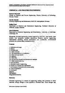
gas-phase reactor, hereafter called a regenerative thermal reactor (RTR). High temperatures are necessary to: • Activate the reactive system from a chemicalthermodynamics standpoint • Quicken kinetics • Reduce byproducts. Practically, the reactants are injected into a common chamber in pre-mixed or un-mixed mode, and then reacted. As a result, these contaminants are “regenerated” into valued products. FIG. 1 shows a concept process flow diagram. The regenerative thermal oxy-reduction between H2S and CO2 occurs in the RTR refractory lined chamber, assisted by a minor injection of either air or oxygen. RTR effluent, constituted of products and unreacted feed species, is quenched and cooled in heat exchangers. The effluent is subsequently processed in a catalytic unit (Unit 1), analogous to a Claus SRU section, where it is cooled by means of a train of heat exchangers (sulfur condensers) and treated in catalytic reactors: • The cooling allows the separation of condensed species (Sx) from the main gaseous stream. • A catalytic treatment is necessary to convert SO2 into elemental sulfur. Since the amount of SO2 at the RTR outlet is minor, only one Claus catalytic reactor is needed in Unit 1. O2, air Steam CO2
H2S, CO2
RTR chamber
CO, H2, H2O, SO2, Sx, N2
H2S, acid gas
H2S, CO2
Unit 1
H2S, CO2 CO, H2, H2O, N2
Sx
Description of the synthesis route. The reaction between
H2S and CO2 can take place at a temperature > 1,000°C in a
Unit 2
CO, H2, N2, CO2
H2O
FIG. 1. A concept process flow diagram. Hydrocarbon Processing | JUNE 2016 1
Process Engineering and Optimzation H2S (or acid gases) and CO2 is complex and involves thousands of chemical reactions and more than 100 molecular and radical species. Specific thermodynamic-kinetics models must be used for a detailed study of an RTR. For this study, a reactions database and calculation package that is available at Politecnico di Milano (Italy) has been used. It has been observed that oxy-reduction This package has been validated on more than 20 industrial-scale Claus SRUs.1 The following reaction reactions between H2S and CO2 results macrosteps are expected to occur in the RTR: are feasible. This reaction may prove to be • Thermal decomposition of H2S into hydrogenated free radicals (SH, H, etc.), a pioneering synthesis route for syngas. thermal activation • CO2 reduction to CO by free radicals (H, OH, etc.) • Propagation of oxygen-based free radicals This improves overall process selectivity on sulfurous • Formation of sulfurous oxides (e.g., SO) and inhibition species, but it also reduces the process yield as a portion of backward reaction from CO to CO2 , according to the of CO is consumed and CO2 is produced. • Finally, effluent undergoes a separation treatment inhibition effect observed by Mueller et al.2 (Unit 2) where water is knocked down, unreacted • Formation of stable SO2 from SO H2S and CO2 are recycled to the RTR, and an H2 / • Formation of H2. The resulting overall RTR reaction is CO2 + 2H2S = CO + CO-rich mixture is exported. The RTR looks like a Claus SRU thermal reactor from a reH2 + S2 + H2O, plus byproducts and unreacted feed species. It action kinetics and reactor engineering standpoint. As a conseshould be noted that such a reaction is chemically more noble quence, the investigating approach and tools used for an SRU can than a traditional Claus reaction, as the hydrogen in H2S is not be also adopted for the RTR. The reaction mechanism between nailed in water and then lost forever, but is instead freed to form H2. A more detailed description on the synthesis route can be found in literature.3 H2S, CO2, recycle Regenerative section Recuperative section The above synthesis route is also superior from a thermodyH S, acid gas namic standpoint to a traditional Claus thermal unit. The overHP 2 O2, or air steam all reaction of Claus thermal oxidation (H2S + 0.5O2 = H2O + 0.5S2) is strongly exothermic (Ho = –156.98 kJ/mol): as a comCO2 Effluent >1,000°C mon practice, released heat is recovered, generating high- and effluent low-pressure steam, which is a practical but poor method from a thermodynamic standpoint. On the contrary, since RTR reaction is endothermic (Ho = +210.97 kJ/mol), the heat balance FIG. 2. An example of an RTR arrangement. can be adjusted by burning a proper amount of H2S to minimize the generation of steam, therefore improving the thermo0.6 dynamic efficiency of the process. • A second catalytic treatment is necessary to convert byproducts, such as carbonyl sulfide (COS) and CS, as well as residual SO2 and sulfur vapors, into H2S and CO2.
TABLE 1. Input and output RTR compositions for two different reaction temperatures
0.5
Inlet composition
Molar fractions
0.4
0.3
CO2
CO2
0.2
H2S
0.1
0.0 0.00
H2 SO2 0.05
0.10
0.15
0.25 0.20 Residence times
0.30
0.35
0.40
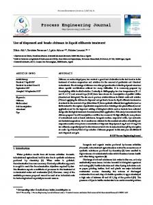
FIG. 3. Concentration profiles of main species against residence time in the RTR.
2 JUNE 2016 | HydrocarbonProcessing.com
10
10
30
30
O2
9.19
3.47
kmol, at 1,500°C, 150 kPa abs
kmol, at 1,300°C, 150 kPa abs
4.47
7.44
CO2
S2
kmol, at 250°C, 150 kPa abs
H 2S
Outlet composition
CO
kmol, at 250°C, 150 kPa abs
H2S
4.32
19.79
S2
11.25
3.98
H2
6.32
3.99
CO
5.4
2.23
SO2
2.25
1.67
H 2O
19.16
6.16
COS
0.13
0.33
Process Engineering and Optimzation • There is no recycle Technology, feasibility and synthesis. The synthesis of • The reactor is ideally plug-flow and adiabatic. syngas originating from H2S and CO2 relies on the RTR feasiThe reaction temperature is set to approximately 1,300°C at bility and overall plant efficiency. The similitude between an an operating pressure of 150kPa. CO2 and H2S react instantaRTR and Claus thermal reactor and, in general, between the proposed synthesis route and traditional Claus SRU, is encourneously; with a residence time of around 0.4 sec., the system can aging for process and technological design. be considered to be at thermodynamic equilibrium. RTR effluAs shown in FIG. 1, fresh reactants (CO2 and H2S coming ent is rich in syngas species and elemental sulfur, whereas H2 S from upstream plants, assisted by air or oxygen) are injected and CO2 concentrations are significantly reduced. Inversely to into the RTR along with recycled reactants. The recycle is not a traditional Claus thermal reactor, SO2 concentration is minor. necessary for the thermal oxy-reduction, but it is essential for It should be noted that the H2 /CO ratio strongly depends improving the self-sustainability of the plant from a process on the residence time and that reactants conversion is strictly standpoint; that is, for the reduction or elimination of exhausts. related to reaction temperature. This is shown in TABLE 1, where Since the RTR reaction is activated at high temperature only, two effluent compositions are given for two different oxy-rereactants can be fed in either premixed or unmixed mode. duction temperatures: the higher the reaction temperature, the The recycle stream pressure corresponds to the Unit 2 ophigher the syngas species yield, and the higher the SO2 , as well. erating pressure; since this is higher than the RTR pressure, Consequently, syngas and SO2 represent a profit and a cost rerecycled H2S and CO2 can be injected into the RTR without spectively—the process is characterized by an optimum. The reaction temperature can be easily adjusted by O2 flowrate. the need of a blower. On the other hand, the recycle must be preheated in some way because its injection at low temperature Unit 1 corresponds to a traditional catalytic Claus SRU secinto the RTR quenches the oxy-reduction. Different methods tion; although the stoichiometry of RTR effluent is different, its are possible for preheating. One of the most conventional is to qualitative chemical composition is the same as catalytic Claus install a heat exchanger where cold recycle and an external hot gas, so the required equipment is also the same. Importantly, fluid cross. Alternatively, the recycle stream temperature can be H2S, CO2 CO, H2, N2 CO2, H2, syngas N2, CO2 H2S, CO2, recycle raised by an inline burner, where natural gas or H2S are combusted by an injection of oxygen or air. A third and energetically efficient solution is to install a feed/effluent type heat exchanger Condenser Absorber SST ripper downstream of the RTR (FIG. 1). Practically, recycle preheating can be done by a combination of these methods. The recycle H2S, CO2 can be also mixed with fresh reactants before preheating and CO, H2, H2O, N2 injection into the reactor. For ensuring a proper production yield, it is essential to minimize regressive reactions during the cooling of RTR effluent. For this purpose, a waste heat boiler (WHB) installed at the outlet of H2O the RTR chamber is the best option, as it can quench the reactions. The WHB and recycle preheating equipment play a key FIG. 4. Within Unit 2, which is conceived as a standard chemical role in the regenerative process, and they could be considered a washing unit, an amine-based solution can be used for knocking down H2S and CO2 in an absorbing column; enabling H2S and CO2 to be portion of the RTR. FIG. 2 shows one of the possible configurarecovered and recycled to the RTR by a stripping column. tions of the RTR and heat exchangers: 1. The recycle is mixed with fresh reactants, preheated in the feed/ (5) (3) effluent exchanger and then O2, air HP HP steam injected into the RTR. steam 2. The oxy-reduction takes place (4) H2S, CO2 (1) RTR chamber at high temperature in the CO, H2, H2O, Acid gas (14) CO, H2, (6) SO2, Sx, N2 CO2, N2 refractory lined chamber. 3. Effluents are quenched in the LP steam LP steam boiler and used for preheating. LP (8) (7) (10) (12) On the whole, the RTR could also steam Condenser be seen as a system constituted of + a “regenerative” and a “recuperative” Amine unit section, and not just the reaction (9) LP steam (13) Water chamber itself. FIG. 3 and TABLE 1 illustrate some therUnit 1 Unit 2 modynamics-kinetics simulation results, based on Politecnico di Milano’s software, Sx (11) (2) for a simplified RTR. It is assumed that: • Fresh reactants (CO2 , H2S and H2S, CO2 O2 ) are pure and with an exact FIG. 5. A process plant scheme with recycle preheating by a feed/effluent exchanger. stoichiometric ratio Hydrocarbon Processing | JUNE 2016 3
Process Engineering and Optimzation (3) O2, air (1)
HP steam
HP steam (5)
RTR chamber
Acid gas (4) FG
H2S, CO2 CO, H2, H2O, SO2, Sx, N2 (14)
(6) LP steam
LP steam
(7)
(8)
(10)
(9) LP steam
LP steam (12) Condenser + Amine unit
(13)
Unit 1
Unit 2 Sx
(11)
(2) H2S, CO2
FIG. 6. A process plant scheme with preheating by an external source and cofiring.
since the amount of SO2 coming from the RTR is minor with respect to Claus thermal section, SO2 can be removed by H2 S in one catalytic passage (Claus reaction: 2H2 S + SO2 = 1.5S2 + 2H2 O). A second and final catalytic reactor provides for the hydrogenation of residual traces of SO2 and sulfur vapors (×H2 + Sx = ×H2S ). COS/CS2 hydrolysis and shift conversion also take place on the hydrogenation catalyst. As a result, the hydrogenation step has the intrinsic advantage to produce H2 , but also the intrinsic disadvantage to consume CO and produce CO2 . Separation of syngas species from H2 S and, partially, from CO2 , is accomplished in Unit 2. To completely remove water, a contact condenser may be necessary before the washing. Due to the acid behavior of H2 S and CO2 , Unit 2 is conceived as a standard chemical washing unit (FIG. 4). An amine-based solution can be used for knocking down H2 S and CO2 in an absorbing column; then, H2 S and CO2 are recovered and recycled to the RTR by a stripping column. Excess CO2 leaves along with the syngas, so a subsequent separation, like washing or selective membrane, may be necessary according to the use of gas. RTR vs. Claus SRU. This synthesis route can potentially replace a traditional Claus SRU. In this case, acid gas coming from the upstream amine unit represents the fresh reactant; again, a minor injection of air or oxygen is necessary. In FIGS. 5 and 6, two different possible process schemes are detailed (the stream number is reported in brackets). Simulations have been carried out by a commercial process package coupled with the aforementioned SRU thermodynamics-kinetics database. FIG. 5 is based on recycle preheating by a feed/effluent exchanger, as sketched in FIGS. 1 and 2. The recycle is first mixed with fresh acid gas and then heated by hot effluent coming from the RTR and the WHB. Conversely, FIG. 6 is based on preheating by an external hot fluid (HP steam) and an injection of fuel gas in the RTR (cofiring) for ensuring proper reaction temperature. Unit 1 and Unit 2 are the same for both schemes. For comparative reasons, the reaction temperature in the RTR is kept at 1,180°C for both schemes. Hot effluent 4 JUNE 2016 | HydrocarbonProcessing.com
CO, H2, CO2, N2
Water
from the RTR is first quenched in the WHB to approximately 890°C and then cooled in the feed/effluent HE to 540°C; hot effluent is completely quenched and cooled in the WHB to 390°C. Effluent from the RTR is rich in hydrogen and carbon monoxide; these syngas species passively flow to the hydrogenation reactor, where significant portions of CO and CO2 are consumed and produced, respectively. Gas exported from Unit 2 is rich in H2 . Such gas, after proper purification, can be used in hydrogenation processes or, after partial CO2 removal, as a syngas. For instance, the required stoichiometric ratio for methanol synthesis is reached by removing two thirds of the CO2 . Therefore, a subsequent purification/ washing operation could be necessary, depending on the application.
Conclusions. H2 S and CO2 can be used to produce a mixture rich in H2 and CO. Such a synthesis route, from preliminary thermodynamics and kinetics studies, appears feasible; moreover, its similarity to the traditional Claus sulfur recovery process makes it promising from a technological standpoint. A few configurations of the RTR have been presented. The overall process can potentially replace the traditional Claus SRU. A cross-check with a laboratory-scale RTR is in progress. LITERATURE CITED Manenti, F., D. Papasidero, A. Frassoldati, G. Bozzano, S. Pierucci and E. Ranzi, “Multi-scale modeling of Claus thermal furnace and waste heat boiler using detailed kinetics,” Computers and Chemical Engineering, Vol. 59, 2013. 2 Mueller, M. A., R. A. Yetter and F. L. Dryer, F.L., “Kinetic modeling of the CO/ H2O/O2/NO/SO2 system: Implications for high-pressure falloff in the SO2 + O (+M) = SO3 (+M) reaction,” International Journal of Chemical Kinetics, Vol. 32(6), 2000. 3 Manenti, F., “CO2 as feedstock: A new pathway to syngas,” Computer Aided Chemical Engineering, Vol. 37, 2015. 1
GIOVANNI MANENTI holds a PhD in chemical engineering from Politecnico di Milano, Italy. He is heat transfer technology manager at Alfa Laval Olmi SpA in Italy. Dr. Manenti has 15 years of experience in engineering and pressure vessels manufacturing companies. His activity is focused on the detailed process design of shell-and-tube heat exchangers and high-pressure process gas boilers for petrochemical and reforming gas plants, including heat transfer technology for chemical reactors and prototype equipment. LUCIO MOLINARI spent 45 years as a process engineer and technology specialist in some of the major Italian engineering companies operating in the nuclear and oil and gas industries. He holds an MS degree in chemical engineering from Università di Genova, Italy, and an MS in philosophy of science from Università di Milano, Italy. He has dedicated the last three decades to gas treatment and sulfur recovery technology. FLAVIO MANENTI is a professor of chemical plants and operations at Politecnico di Milano, Italy, where he leads the Centre for Sustainable Process Engineering Research (SuPER). He has been elected as a charity trustee at the European Federation of Chemical Engineering (EFCE) and awarded the Alexander von Humboldt Prize for senior scientist. His applied research on modeling, control and optimization is strictly related to practical applications on more than 40 industrial projects.