XIV Iberchip Workshop
Puebla, Mexico, February 20 - 22, 2008
DESIGN AND IMPLEMENTATION OF A MITCHELL-BASED LOGARITHMIC CONVERTER FOR A FLOATING POINT COPROCESSOR Oscar Robles Palacios, Joel Muñoz Quispe, Mario Raffo Jara, Carlos Silva Cárdenas Grupo de Microelectrónica Sección de Electricidad y Electrónica Pontificia Universidad Católica del Perú
[email protected],
[email protected],
[email protected],
[email protected] ABSTRACT This paper presents a method to approach the implementation of a highly accurate logarithmic converter that operates with floating point numbers. For consistency purposes, it was necessary to adopt a standard to represent all floating point number. Hence, the IEEE Standard for Binary Floating-Point Arithmetic (IEEE 754) was the one selected. This logarithmic converter is based on Mitchell’s algorithms approximations. Thus, it was necessary to add an error correction unit to the architecture. Despite of this, the processing speed of this logarithmic converter is not affected. The system implemented reduces the maximum error percent down to 0.541 percent, and performs the binary-to-binary logarithmic conversion using 3 clock cycles. 1. INTRODUCTION Real-time accurate digital signal processing has become essential for complex applications in a variety of fields, such as telecommunications, audio, video, etc. Therefore, the necessity to perform precise and fast arithmetic operations, besides low power consumption, is the main objective of processors designers. This tendency fostered the use of the logarithm to simplify complex arithmetic computations. By using the logarithm, multiplication and division can be abridged with addition and subtraction [4], roots and power problems can be reduced to multiplication and division, respectively [2]. This advantage of the logarithm has been used to implement more complex arithmetic units, such as the ones developed in [1]. Mitchell’s algorithm is based on a straight-line approximation of the log2 function, which provides a limited accuracy. This drove several researchers to improve this algorithm and develop different methods for error correction. The most common one consisted on dividing the log2 function in regions or intervals, and perform the straight-line approximation on each of these
ISBN-13 978-968-7938-03-5
regions. Although these error approximation techniques provided a more accurate result, the circuitry involved was much harder to implement. More complex hardware means lower processing speed. As a result, many DSP applications have some tolerance for error that is compensated with high speed processing and smaller area use [2]. We have presented here an implementation of a 32-bit - established by the standard IEEE 754 [3] - floating point logarithmic converter. One of the principal blocks of this logarithmic converter is LOD (Lead One Detector), which is used to find the leading-one position for data up to 8 bits. Another important stage of this converter is the Error Corrector, which is based on multipliers, dividers and full adders used to achieve a linear curve fitting of the theoretical value of the log2 function from the Mitchell’s approximation. The accuracy achieved by this logarithmic converter is far superior to the Mitchell’s approximation and requires neither a large amount of hardware nor a long processing time. This paper is divided in 6 sections: section 2 reviews the theory behind binary logarithms; section 3 describes the mathematical foundations of the improvements induced by the Error Corrector; section 4 explains the entire architecture of the Logarithmic Converter; section 5 gives details of the implementation outcomes; and section 6 provides some conclusions. 2. BINARY LOGARITHM Binary logarithm analysis is performed by Mitchell in his paper [2]. The information is summarized as follows: Let there be a binary number N, located inside the interval 2j ≤ N ≤ 2k+1; j = 0, ±1, ±2, …; and k = 0, ±1, ±2, …; and k > j. The binary representation of the number N is: N = zk…z2z1z0.z-1z-2…zj. So N can also be represented as follows: k
N = ∑ 2i zi , i= j
(1)
XIV Iberchip Workshop
Puebla, Mexico, February 20 - 22, 2008
Table 1. Error correction factors.
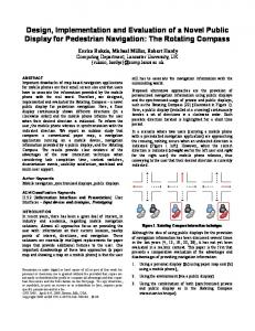
Fig.1. Dependency of the real value of log2 on the Mitchell’s approximation. where zi can take the value of ‘1’ or ‘0’. Now, we are going to assume that zk = ‘1’ since it is the MSB (Most Significant Bit). Consequently, N can be expressed as k −1
N = 2 k ∑ 2i zi ,
(2)
Mantissa's range 2^23[0.0000:0.0625[ 2^23[0.0625:0.1250[ 2^23[0.1250:0.1875[ 2^23[0.1875:0.2500[ 2^23[0.2500:0.3125[ 2^23[0.3125:0.3750[ 2^23[0.3750:0.4375[ 2^23[0.4375:0.5000[ 2^23[0.5000:0.5625[ 2^23[0.5625:0.6250[ 2^23[0.6250:0.6875[ 2^23[0.6875:0.7500[ 2^23[0.7500:0.8125[ 2^23[0.8125:0.8750[
A 1,3750 1,2500 1,2500 1,1250 1,1250 1,1250 1,0000 1,0000 0,9375 0,8750 0,8750 0,8750 0,8125 0,7500
B 3751 45350 119900 220300 341300 478400 682400 788600 956600 1131000 1310000 1493000 1678000 1865000
2^23[0.8750:0.9375[ 2^23[0.9375:1.0000[
0,7500 0,7500
2053000 2242000
i= j
If we factorize 2k out, we obtain
Error = log 2 (1 + m) − m ,
k −1 N = 2 k 1 + ∑ 2 i −k z i , i= j
(3)
Then, we analyze only the term k −1
m = ∑ 2 i−k z i ,
(4)
(9)
Since this logarithmic converter works with the standard IEEE 754, the Mitchell’s approximation is ideal considering the format of the floating point numbers [3]. This can be visualized reviewing the standard: Any number M must be express in the following format:
M = (−1) S (1 + m)2 E ,
(10)
i= j
Since k ≥ j, m will be inside the interval 0 ≤ m ≤ 1 and
N = 2 k (1 + m) ,
log 2 N = k + log 2 (1 + m) ,
(5) (6)
As a matter of fact, m is the binary fraction of the mantissa that is conformed by all the bits located at the right of the leading-one in binary word [2]. The linear approximation proposed by Mitchell, (log2N)’, is expressed as
(log 2 N )' = k + m , Therefore, the error induced by approximation is represented as follows:
Error = log 2 N − (log 2 N )' ,
ISBN-13 978-968-7938-03-5
(7) Mitchell’s
(8)
where S sets the sign of the number (always positive as far as the logarithmic is concerned), m is the binary fraction of the mantissa, and E is the exponent used to represent the contribution of the original MSB of M. The standard IEEE 754 establishes S as a 1-bit word, m as a 23-bit word, and E as an 8-bit word [3]. Thus, the system works with 32-bit words. Hence, if we apply Mitchell’s algorithm to calculate (log2M)’, we will get
(log 2 M )' = E + m ,
(11)
And the corresponding error will be the expression described in (9). It is clear now how Mitchell’s algorithm will facilitate the calculation of the logarithm for floating point numbers. Nevertheless, as it was mentioned before, the error correction stage is necessary to obtain a high accuracy system.
XIV Iberchip Workshop
Puebla, Mexico, February 20 - 22, 2008
Fig. 2. Logarithmic Converter’s scheme
3. IMPROVEMENTS TO MITCHELL’S ALGORITHM For the Error Corrector block, it was decided to divide the curve 223(log2(1+m)) vs. 223(m), depicted in Fig.1, in 16 proportional regions. This curve was selected in order to work the real binary number that will be needed for the implementation on the FPGA. After analyzing all the regions of the curve, a straight-line approximation is applied to each one of them. Thus, every error correction factor can be represented by a linear equation, as expressed in
2 23 (log 2 (1 + m)) = A(2 23 (m)) + B ,
(12)
The values for both of the coefficients (A and B) are calculated for each region, and are shown in table 1. As it is clear to see, all the values of the A coefficient can be calculated by multiplications and divisions by a 2 power number; for example: 0.75 can be expressed as (3/4). Since divisions by a 2 power number for binary numbers are implemented by shift-rotate algorithms, the hardware use for the divider was very simple and did not induce a high delay, as most dividers do. Hence, the error correction is made by a series of linear curve fitters, implemented with high speed multipliers, dividers and full adders. 4. THE LOGARITHMIC CONVERTER The 32-bit floating point logarithmic converter is shown in Fig. 2. The register FP_IN is the one carrying the data that needs to be processed. The MSB – or FP_IN(31) – of this register is the S variable, which is the one that sets the sign of the floating point number.
ISBN-13 978-968-7938-03-5
Since the operation to perform is log2, we assume all numbers that will arrive to this unit will be positive (S = ‘0’). Thus, no operation is needed with this signal and it passes through the entire system without being altered. The next 8 bits located to the right of the MSB of the register – or FP_IN(30:23) – carry the information of the exponent of the floating point number (E). Finally, the last 23 LSBs (Lowest Significant Bits) – FP_IN(22:0) – carry the information of the fraction portion of the mantissa (m). The architecture implemented is pipelined to perform the entire binary-to-binary logarithmic conversion in 3 clock cycles. It was necessary to apply this pipeline technique in order to obtain a stable, glitch free and fast converter. These last three characteristics will become very in handy for the future coprocessor that will use this converter to perform all of floating point computations. The most important stage of this system is the Error Corrector block. As described in section 3, Mitchell’s approximation is to be modified in order to obtain a more accurate result, and the alteration is described by (12). Inside this stage, the 4 MSBs of the m are used to its appropriate region in order to select the suitable coefficients. The 4 MSBs act as the address signal for three different initialized RAMs that comprise the appropriate coefficients for the multiplication, division and final addition simultaneously. For optimization purposes, it was decided to implement the multiplier (crucial part of this stage) with the 9-bit embedded multipliers of the FPGA. Since all division factors are 2 power numbers, the divider consisted only on a register that selects the proper bits of the signal. For example, if the division factor is 16 = 24, the register will only select the 19 MSBs of the signal (23-bit word). Finally, the addition is performed by a full adder. The Real Exponent Finder block has to alter the exponent given (E) because of the parameters set by the IEEE 754 standard, which establishes that all exponents must be added with 127. Therefore, all exponents will range from 127 to 255. The necessary operation is a subtraction between E and 127, which is not in any way complicated. This operation was implemented with an 8bit subtraction executer, based on 1-bit full adders, which inputs are E and the binary number for 127 = “01111111”. Thus, there is practically no delay induced by the computation. The LOD block follows the Real Exponent Finder block. In this case, the LOD must detect the leading-one position of the real exponent (Er) in order to identify how many LSBs of the corrected fraction portion of the mantissa (mc) has to be dropped. This may appear as an information loss, but it does not affect the accuracy of the converter, and it is necessary to fit the word length of the standard IEEE 754. The Concatenation Executer is in charge to alter mc depending on the output of the LOD, and join it together with Er in order to obtain the new fraction portion of the mantissa. It is important to clarify that the MSB of the Er
XIV Iberchip Workshop
is automatically discarded because, as it was stated before, the standard IEEE 754 keeps fraction
Puebla, Mexico, February 20 - 22, 2008
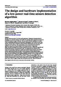
This logarithmic converter is as accurate as it is fast. The improvements to the Mitchell’s approximation are huge, and they can be visualized in Fig. 3. The result of the error analysis gives a maximum of 0.541 percent and has a linear (and almost constant) behavior in most regions. This means that the system is not only highly accurate but also predictable. 6. CONCLUSIONS
Fig. 3. Error percent of both logarithm approximations portion of the mantissa. The IEEE_754 Formatter is in charge of getting the appropriate exponent for the output according to the standard mention above. This operation is performed by a 8-bit full adder, based on 1-bit full adders, which provides no delay whatsoever. Finally, at the last stage of the pipelined architecture, the S variable is assigned to the MSB of FP_OUT register – or FP_OUT(31) – without any alteration; the output of the IEEE_754 Formatter is allocated in the next 8 MSBs – or FP_OUT(30:23) – of the FP_OUT register; and the output of the Concatenation Executer is assigned to the 23 LSBs – or FP_OUT(22:0) – of the FP_OUT register. 5. IMPLEMENTATION AND RESULTS This logarithmic converter was synthesized on the Cyclone II FPGA, specifically EP2C35F672C6N. This system used 165 LE (Logic Elements), 3 RAMs, and 3 embedded 9-bit multipliers. The system was designed and implemented to work with a clock frequency of 50 MHz, and provides a worst case scenario delay of 8.7 ns on each stage of the pipelined architecture.
ISBN-13 978-968-7938-03-5
The 32-bit floating point logarithmic converter has been presented. This logarithmic converter has a higher performance than the Mitchell’s approximation, and provides a highly accurate and fast result. The region division method for error correction of the Mitchell’s algorithm is the most optimum one. However, it is necessary to analyze the trade off among the hardware required for the approximations, the accuracy we want to achieve, and the latency introduced by complex hardware implementations, before giving away the quality of high performance to the architecture implemented. This unit and similar ones are the cores of the processors and coprocessors dedicated to arithmetic computations. Hence, pipelined techniques are recommended for stability and consistency purposes. 7. REFERENCES [1] D. McLaren, “Improved Mitchell-Based Logarithmic Multiplier for Low Power DPS Applications,” Proceedings, IEEE International, SOC Conference, pp.53-56, Sept. 2003.
[2] K. Abed, R. Siferd, “CMOS VLSI implementation of a low-power Logarithmic Converter,” IEEE Transactions on Computers, pp. 1421-1433, Nov. 2003. [3] “What Every Computer Scientist Should Know About Floating-Point Arithmetic,” Numerical Computation Guide, Sun Microsystems, pp. 171-264, Dec. 1996. [4] J. N. Mitchell, “Computer Multiplication and Division Using Binary Logarithm”, IRE Transactions on Electronics Computers, Vol. EC-11, pp.512-517, Aug. 1962.