of ADC as close to the antenna as possible. ... (UE), since the chances for channels interference among the standards is very .... Polyphase Filter Bank with +-j Rotators. X[n]. Y[n] .... loading instructions for the process that anchors the data .... based Multi-Standard Software Radio Receiverâ, Master of Engineering. Thesis ...
Design and Implementation of an FPGA-based Multi-Standard Software Radio Receiver Mehmood-Ur-Rehman Awan, Muhammad Mahtab Alam, Peter Koch, Nastaran Behjou Department of Electronic Systems, Technology Platform Section Aalborg University Denmark Email: (mura, mma, pk, nab)@es.aau.dk
Abstract—The aim of this work is to design and implement an FPGA-based Multi-Standard Software Radio Receiver. WLAN and UMTS are taken as the case study. Xilinx FPGA VirtexIV is the target platform. Bandpass sampling technique at 840MHz is used to alias the combined band of WLAN and UMTS. In the channelization process, in contrast to conventional channelizer, polyphase channelizer is employed. The designed prototype filter for WLAN has 50 taps, partitioned into 5 polyphase sub-filters whereas for the UMTS the prototype filter has 2520 taps, partitioned into 210 polyphase sub-filters. In the implementation, serial polyphase structure with parallel MAC is selected. An implementation analysis based on the area requirements for multipliers, adders and registers for different structures is performed. For 16-tap filter, the structures for Parallel-Multiply and Accumulate, DA, Fast FIR, and Frequency domain filtering require 2896 (without adders), 3072, 4064, and 5572 slices, respectively. The DA is found to be suitable for the implementation due to being resource efficient. Polyphase subfilter is implemented with Distributed Arithmetic structure and also with Xilinx-DSP48 slices for improved performance.
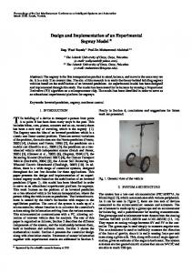
I. I NTRODUCTION Rapid growth of wireless communications and the emergence of new standards increase the demand for low cost multi-mode radio receivers. For portable battery-powered receivers a high level of integration, high flexibility, and low power dissipation are precedence objectives [1]. One approach to achieve multi-mode operation in a receiver is to design hardware, which can be reconfigured by software. This approach is related to the concept of software-defined radio (SDR) [2]. In transition from traditional radio architectures to softwaredefined radio, most of the signal processing is shifted from the analog to the digital domain. This is feasible through shifting of ADC as close to the antenna as possible. This imposes more stringent performance requirements on the analog-todigital (A/D) conversion, where a high dynamic range must be combined with a high sampling rate [3]. A scenario of multi-standard multi-mode is shown in Fig. 1. In this paper, a multi-standard software radio receiver is designed and implemented. One of the main challenges is the coexistence of several standards in one user equipment (UE), since the chances for channels interference among the standards is very high [4]. Therefore, out of the several existing multi-standards i.e. GPS, GSM, Bluetooth, zigbee, satellite communication, the application is limited to a case study where two standards being UMTS and WLAN are considered as shown in Fig. 1. This is a case study which fits to the
SATELLITE
DVB, DAB
GSM, 3G, WIMAX
BLUETOOTH, ZIGBEE
UMTS Downlink WLAN Downlink
User Equipment (UE)
Fig. 1. A scenario of multi-standard multi-mode ”all-in-one” front-ends user equipment. It highlights the user equipment capable of receiving two standards i.e. UMTS and WLAN.
cellular systems where the possible scenario could be that a doctor is talking with a patient on the UMTS mobile phone and at the same time he is down-loading the medical record of that patient through WLAN. Some of the specifications of these standards are shown in Table I [4].
Duplexing Frequency Band (GHz) Rx Sensitivity Tx Power Level Channel Bandwidth Non-overlap channels
UMTS FDD 1.920 - 1.980 : UL 2.110 - 2.170 : DL -117 dBm 24 dBm (Class 3) 3.84 MHz 12
IEEE 802.11g TDD 2.4 - 2.4835 -82 to -65 dBm 20 dBm (Europe) 16.6 MHz 3
TABLE I S OME SPECIFICATIONS OF UMTS AND WLAN STANDARDS [4]
A software radio receiver architecture is presented in Fig. 2. The idea in this paper is to use an efficient technique called bandpass sampling which can directly sample the Radio Frequency (RF) signal after Low Noise Amplifier (LNA), and all the signal processing to be done in digital domain. It will overcome the problems such as the I/Q imbalance of analog components of digital radios or even software defined radios. Moreover, by processing the digital data, the unique functionalities of each standard can be set in the digital signal processing programmable parts by employing the similar concept as that of software-defined radios. This enables the front-end to process numerous signals in the digital domain
Proceedings of the 25th Norchip Conference. 19-20 Nov 2007. Aalborg, Denmark. ISBN (electronic): 1-4244-1517-9
without the traditional hardware limitations. LO_1_B
Digital Base Band
Digital IF
LNA
RF
BandPass Sampler
IF
Band Limit Filter
Base Band Proc LO_1_C LO_N_B
Quantizer
Digital IF
.. . . ..
Digital Base Band Base Band Proc
LO_N_C
Fig. 2. The proposed architecture of the software radio, where sampling is done at RF just after the LNA which is the only analog component in this architecture.
II. S YSTEM D ESIGN Polyphase channelizer is the most efficient approach in term of computations and required hardware resources as compared to standard channelizer [5]. Based on the unique features of the polyphase channelizer, we have chosen it, to design and implement the system. The relation among the sampling frequency, channel spacing and number of channels for the polyphase channelizer is [6]: fs
=
N × ∆f
(1)
where fs is the input sampling frequency, N is number of channels/transform size and ∆f is the inter channel spacing. There are two constraints that have to be met in polyphase channelizer [10]. • The channels to be down-sampled and down-converted to baseband should be centered on the multiples of the channel spacing or on the multiple of quarter of their channel spacing respectively. • The number of channels (N) must be integer. The sampling frequency of 840MHz [5] is selected after examining different sampling frequencies, which fulfills the two mentioned constraints. The RF spectrum of WLAN and UMTS is aliased down to lower spectrum range between (36410) MHz which is shown in Fig. 3. Bandpass Sampling : A band including multi-standards (UMTS & WLAN) is undersampled @ 840 MHz and the Nyquist frequency band (0-420MHz) contains the aliases of the standard signals. The aliases of the combined band of 374MHz are non-overlapped. The WLAN and UMTS both are spectrally inverted in the Nquist frequncy zone. Nyquist frequency Zone
36
UMTS
WLAN
Aliased UMTS
Aliased WLAN
BW = 374
2400
2484
120 350 2110
2170
410
0
fs/2 420
fs 840
3fs/2 1260
2fs 1680
5fs/2 2100
3fs
F (MHz)
2520
Fig. 3. The combined spectrum of UMTS and WLAN is bandpass sampled at 840MHz, and the resulted aliases in the Nyquist zone are spectrally inverted.
According to Eq. 1, polyphase channelizer for WLAN has 35 channels of 24MHz and UMTS has 168 channels of 5MHz at 840MHz. However the required channels for WLAN and
UMTS are 3 and 12 respectively. This puts an extra load on the filtering process in terms of high clock speed requirement and large memory storage for filter coefficients. One of the techniques to solve the problem is to re-sample the data before the polyphase channelizer as shown in Fig. 4. The sampled signal can be re-sampled by large factors such that the resultant sampling frequency is above the total signal bandwidth, if the incoming signal is image free. The re-sampling process in this case is simply the spectrum translation [5]. Based on this technique, the WLAN and UMTS bandpass filters are made complex and the resultant image free signals for WLAN and UMTS are tried by different re-sampling factors to have the minimum possible sampling frequencies, which are listed in Tables II and III. Down-sample factor 5 6 7 8 10& above
New Sampling Freq.(MHz) 168 140 120 105 84 & below
Channel Status non-overlapped, non-integer non-overlapped, non-integer non-overlapped, integer non-overlapped, non-integer < 84.5MHz bandwidth
TABLE II R E - SAMPLING FACTORS FOR WLAN WITH COMPLEX SIGNAL , SHOWING THE CHANNEL STATUS AS OVERLAPPED / NON - OVERLAPPED AND RESULTING NUMBER OF CHANNELS AS INTEGER / NON - INTEGER .
Down-sample factor 4 7 8 10 12 14 15& above
New Sampling Freq.(MHz) 210 120 105 84 70 60 below 60
Channel Status non-overlapped, integer non-overlapped, integer non-overlapped, integer non-overlapped, non-integer non-overlapped, integer non-overlapped, integer < 60MHz bandwidth
TABLE III R E - SAMPLING FACTORS FOR UMTS WITH COMPLEX SIGNAL , SHOWING THE CHANNEL STATUS AS OVERLAPPED / NON - OVERLAPPED AND RESULTING NUMBER OF CHANNELS AS INTEGER / NON - INTEGER .
The desired rate for WLAN and UMTS at the baseband is 20MHz and 61.44MHz respectively. Table II shows that a maximum re-sampling factor of 7 for WLAN is possible which results in a new sampling frequency of 120MHz, with 5 channels of 24MHz which fits the non-overlapped channel criterion. Table III shows the maximum possible re-sampling factor of 14 for UMTS, that results in the new sampling frequency of 60MHz. In order to have desired UMTS rate of 61.44MHz, an embedded re-sampling factor of 125/128 is required. Similarly, with the other two re-sampling factors of 12 and 8, embedded re-sampling factors of 875/768 and 875/512 are required. In this rational number embedded resampling, we have to design the prototype filter at up-sampled frequencies. To have the minimum up-sampled factor, embedded re-sampling factor of 875/512 is selected and is rounded
Proceedings of the 25th Norchip Conference. 19-20 Nov 2007. Aalborg, Denmark. ISBN (electronic): 1-4244-1517-9
Polyphase Input Data Registers
to 17/10. Finally, re-sampling factors of 7 and 8 are selected for WLAN and UMTS, resulting in new sampling frequencies of 120MHz and 105MHz respectively. This is illustrated in Fig 4 and is summarized in table IV. Cases
Sampling rate (MHz) 105 120
UMTS WLAN
Channel Spacing (MHz) 5 24
No. of Channels 21 5
TABLE IV S PECIFICATIONS FOR THE CHANNELIZER FOR UMTS AND WLAN
Channel Selector M=7 WLAN REPOLYPHASE SAMPLER CHANNELIZER 120 MHz
WLAN BANDPASS FILTER (36-120) MHz
Combine band of UMTS & WLAN (2110 - 2484) MHz Bandpass ADC
Baseband Processing
Output rate @20 MHz
Bandpass Sampling @ 840 MHz
DSP
M=8 UMTS REPOLYPHASE SAMPLER CHANNELIZER 105 MHz
(350-410) MHz BANDPASS FILTER
UMTS
Output rate @61.44 MHz
0
6
1
12
7
2
5
1
11
6
1
2
4
2
10
5
3
3
3
9
4
4
2
4
8
3
1
(A)
(B)
Fig. 6. Successive serpentine data shifts for WLAN in polyphase memory and data load for 6:1 re-sampling in a 5-stage polyphase filter. It shows data load operations for first two states.
The corresponding band of UMTS channels translate to (37.5 to -12.5) MHz after re-sampled by a factor of 8. With new sampling frequency of 105MHz and channel spacing of 5MHz, the number of channels become 21 which is the number of the polyphase decomposition. The prototype filter for UMTS has 2520 taps, partitioned into 210 polyphase subfilters which results in 12 taps per sub-filter. The polyphase channelizer for UMTS is shown in Fig 7. Polyphase Channelizer (UMTS)
Fig. 4. System block diagram having re-samplers prior to UMTS and WLAN channelizers.
π/21)
j0k'(2
Polypha se Partition
0
The corresponding band of WLAN channels translate to (-42, -12 and 48) MHz after re-sampled by 7. With new sampling frequency of 120MHz and channel spacing of 24MHz, the number of channels becomes 5 which is the number of the polyphase decomposition. The prototype filter for WLAN has 50 taps, partitioned into 5 polyphase sub-filters which results in 10 taps per sub-filter. The polyphase channelizer for WLAN is shown in Fig 5.
Polyphase Input Data Registers 0
e
H (+-jZ) 0
2
2 j1k'(2
e
1
π/21)
H (+-jZ) 1
2
X[n]
Y[n]
2
π/21)
j2k'(2
e
2
2
K’ = k+(s/4)
H (+-jZ) 2
2
2
s : 2 k : ( 7,
π/21)
12, 10,
21-1
Polyphase Channelizer (WLAN)
H
(+-jZ)
21-1
2
5,
2
3,
CH1 :
K’ = 7+(2/4)
CH12:
K’ = 6+(2/4)
8,
Poly phase Filte r Ba nk with +-j Ro tators
π/5)
j0k'(2
Polypha se Partition
0
e
H (+-jZ)
Fig. 7. UMTS channelizer: k and s are tunning parameters. k is the channel number and s is the offset of multiples of quarter of the channel spacing.
0
2
2 j1k'(2
e
1
π/5)
H (+-jZ) 1
2
X[n]
Y[n]
2
π/5)
j2k'(2
e 2
2
H (+-jZ) 2
2
2
K’ = k+(s/4)
j(5-1)k’(2
e 5-1
k : (2,3,4) s : (0,1,2)
π/5)
H (+-jZ) 5-1
2 Poly phase Filte r Ba nk with +-j Ro tators
2
CH1:
K’ = 2+(0/4)
CH2:
K’ = 3+(1/4)
CH3:
K’ = 4+(2/4)
Fig. 5. WLAN channelizer: k and s are tunning parameters. k is the channel number and s is the offset of multiples of quarter of the channel spacing.
The down-factor to have 20MHz required rate at 120MHz sampling frequency is 6. This is realized by down-sampling by serpentine shifting data through the filter in stride of length 6. The process is illustrated for two data load iterations in Fig 6.
The down-factor to have 61.44MHz target rate at 105MHz sampling frequency is 1.7 or 17/10. This ratio can be realized by first up-sampling the input stream by 10 and then downsampling it by 17. The up-sampling is performed by zero packing the input data and down-sampling by serpentine shifting data through the filter in stride of length 17 [7]. The process is illustrated for two data load iterations in Fig 8. There is no actual zero packing in the final configuration. In the first data load, shown in Fig 8(A), 2-actual data samples are delivered to the 17 register addresses, while in the second load 2-actual data samples are delivered to the next 17 register addresses as shown in Fig 8(B). The data loading procedure is found to be periodic in 210-load cycles for which it will require 210-states to control the process. The Least Common Multiple (LCM) of 21 and 17 is 357, and since 17 zero packed inputs are delivered at a time, 21 states are needed. For up-sampling factor of 10, the LCM of 21 and 10 becomes
Proceedings of the 25th Norchip Conference. 19-20 Nov 2007. Aalborg, Denmark. ISBN (electronic): 1-4244-1517-9
1,
20, 18, 16, 14,
j(21-1)k’(2
e
6)
0 1 2 3 4 5 6 7 15 16 17 18 19 20
Polyphase Input Data Registers 0 0 0 0 0 0 2 0 0 1
0 1 2 3 4 5 6 7 15 16 17 18 19 20
(A)
Polyphase Input Data Registers 0 0 0 0 0 0 0 0 0 2 4 0 0 0 3 0 0 0
0 1
Filter Co-efficients sets C0, C22, C44, C66,...........,C186, C208, C20 C17, C39, C61, C83,..........,C203, C15, C37 C34, C56, C78, C100,..........,C10, C32, C54 — — — C193, C5, C27, C49,..............,C169, C191, C3
TABLE VI UMTS F ILTER C O - EFFICIENTS LOADING SEQUENCE WITH THE STATE MACHINE
(B)
Fig. 8. Successive serpentine data shifts for UMTS in polyphase memory and data load for a 17/10 re-sampling in a 21-stage polyphase filter. It shows data load operations for first two states.
210, which is the periodic interval. Table V lists the memory loading instructions for the process that anchors the data registers and cycles the data load for UMTS channelizer. Note that in the 210-states, a total of 357 inputs are delivered and 210 outputs are taken from the polyphase engine to realize the desired embedded 17/10 re-sampling. The loading scheme is seen to be a constant offset of -10 modulo 21 within a sequence as well as in the transition between sequences. The -10 offset is a consequence of the 1-to-10 up-sampling represented by the zero packing but not actually implemented in the process. State 0 1 2 3 — — 208 209
State 0 1 2 — — — 209
No. of Inputs 2 2 2 1 — — 2 1
Loading Sequence R16, R6 R17, R7 R18, R8, R19 — — R4, R15 R5
TABLE V UMTS P OLYPHASE FILTER ’ S R EGISTER LOADING SEQUENCE WITH THE STATE MACHINE
Because of the 1-to-10 up-sampling implemented by the zero packing, only one-tenth of the weights in each stage actually contributes to the sub-filter output. Thus each stage is further partitioned into 10 subsets of weights, which results in a total of 21 × 10 = 210 filter weight sets. These sets are denoted by C0, C1,...., C209 where the integer is the starting index from the original non-partitioned prototype filter. Each filter starts with its index and increments in stride of length 210. Table VI lists the filter assignment to the 21-successive data registers for 210-states of the process. Table VI shows that in a given state the successive filter index increments by 22 modulo-210 and between states, the filter index increments by 17 modulo-210. The integer 22 is the offset between two data samples in the zero packed load in two adjacent rows. The index 17 is the number of zero packed data points introduced per data load cycle. The prototype filter has to be designed to operate at 10 times fs or 1050MHz due to up-sampling of the data by a factor of ten on the way into the filter. Consequently,
the filter becomes ten times longer than the standard design but since only one-tenth of it is used per processing cycle so no processing penalty is paid [7]. III. I MPLEMENTATION In the implementation phase, polyphase channelizers are analyzed in terms of the required components, consisting of demultiplexer as commutator, a filter bank having polyphase filters, and finally the coherent phase summation. There are different structural techniques which can be used to carry out the implementation. To select the best technique for the designed receiver, general polyphase structure, optimized structures - symmetric property based structure, adder shared structure, serial polyphase structures with serial and parallel MAC are considered. Based on the complexity analysis as shown in Table VII, serial polyphase structure with parallel MAC is selected for the final implementation, as shown in Fig 9. Cases Polyphase General (Transpose form) Symmetric form (Shared Multipliers) Symmetric form (Shared Multipliers & Adders) Serial Polyphase (Serial MAC) Serial Polyphase (Parallel MAC)
# Mults
#Adders
#Regs
N
((N/M)-1)x M
N
Clock speed fs /M
N/2
((N/M)-1)x M
N
2fs /M
N/2
((N/M)x M)/2
Nx2
2fs /M
1
1
N
fs x (N/M)
N/M
(M/N)-1
N
fs
TABLE VII C OMPLEXITY A NALYSIS FOR POLYPHASE FILTER BANK , IN TERMS OF MULTIPLIERS , ADDERS , REGISTERS , AND CLOCK REQUIREMENTS .
In the individual sub-filter implementation, different implementation structures are considered. These being Parallel Multipliers and Accumulate, Distributed Arithmetic, Fast FIR, Frequency domain filtering [8] and Multiplier less filtering techniques. Each structure and its variants are analyzed in terms of hardware resources. The analysis is based on the approximation for the area requirements for multipliers, adders and registers etc. For 16-tap filter Parallel-Multiply and Accumulate, Distributed Arithmetic, Fast FIR and Frequency
Proceedings of the 25th Norchip Conference. 19-20 Nov 2007. Aalborg, Denmark. ISBN (electronic): 1-4244-1517-9
Sampled Data
Shift-Registers Bank
Parallel Multipliers and Adders
Phasor Multiplier
Accumulator
Output Data
Coefficient Array Decoder (State-machine based Controller)
Fig. 9. The basic building blocks of Serial Polyphase Channelizer with Parallel MAC. It consists of Shift Register Bank, Filter’s Coefficient Bank, Parallel Multiply and Accumulate, Phasor Multiplication, Accumulator and Decoder (state-machine based controller) to control the filtering operation.
domain filtering structures require 2896 (without adders), 3072, 4064, and 5572 slices, respectively. The Distributed arithmetic is found to be suitable for the implementation due to being resource efficient. The focus of the above techniques is to use multipliers as little as possible, to save the area. But due to technology advancement, the modern FPGAs have dedicated multiplier blocks which are more efficient than the CLB-slices based multipliers, mainly in terms of operating speed and reduced power requirements. Xilinx FPGA, Virtex-IV has XtremeDSP blocks that can perform multiplication up to 500MHz. The system performance is increased by using these blocks. Each XtremeDSP block has two DSP48 slices [9]. Therefore, the polyphase filter bank implemented as serial-polyphase-filter structure with parallel MAC for WLAN and UMTS channelizer can be built by using 10 and 12 DSP48 slices respectively. In the fixed-point implementation of WLAN channelizer, word-length for Input Data, Filter’s Coefficient, Complex Phasors and Complex Output are taken as 16 Bits (1 sign, 7 Integer, 8 Fraction), 12 Bits (1 sign, 11 Fraction), 16 Bits (1 sign, 1 Integer, 14 Fraction), and 30 Bits (1 sign, 10 Integer, 19 Fraction) respectively. The resource utilization of polyphase channelizer for WLAN is tabulated in Table VIII. The maximum operating frequency of the design comes out to be 134MHz, which is within the desired frequency i.e. 120MHz. Selected Device No. of slices No. of Slice Flip Flops No. of DSP48s
xc4vsx35 1178 out of 15360 1649 out of 30720 14 out of 192
7% 5% 7%
TABLE VIII R ESOURCE U TILIZATION OF WLAN CHANNELIZER
IV. C ONCLUSION We presented a dual-standard software radio receiver architecture. A system designed with resource efficient technique ‘polyphase channelizer’ is used to extract the 12 UMTS and 3 WLAN Channels with desired rate at the baseband. Serial Polyphase filter structure with parallel MAC is considered for the FPGA implementation. The critical analysis in terms of hardware area is carried out, which reflect that Distributed
Arithmetic or Dedicated Xtreme DSP48 blocks are the best and efficient for polyphase channelizer. The sampling frequency is a critical parameter in the whole system design. By having multiple bands the complete spectrum is much wider, so in order to fulfill the Nyquist criterion of f s ≥ 2B, higher sampling frequency is required. This puts more limitations on the selection of hardware platform with high speed ADCs, technology with higher switching speed. There is always room for improvement and following are some of the future work [5]. 1) The polyphase channelizer can be used to its level best features that is extracting all of the channels for any standard, by having a heterodyning at the input of the polyphase channelizer, and heterodyning-carrier is selected such that the translated channels have equal channel spacing. This case will result in extracting all the channels of a standard, just by using standard polyphase channelizer, not by its variant to compensate the offsets of multiples of quarter of channel spacing. 2) In the polyphase channelizer for UMTS, the required downfactor of 875/512 is rounded to 17/10, which results in the output sampling rate of 61.76MHz instead of 61.44MHz. Arbitrary sampling rate technique [10] can be used along with polyphase channelizer to have the exact required sampling rate of 61.44MHz. ACKNOWLEDGMENT The research described in this publication is carried out in Center for Software Defined Radio at Aalborg University. A special thanks to Prof. fredric j harris, San Diego State University (USA), for his valuable guidance for setting up the system design. R EFERENCES [1] X. Li and M. Ismail, “MultiStandard CMOSWireless Receivers: Analysis and Design” Boston, MA: Kluwer, September 2002. [2] J. Mitola, “The software radio architecture”, IEEE Comm. Mag., Vol. 5, No. 5, pp. 26-38, May 1995. [3] B. Razavi, “Challenges and trends in RF design”, in Proc. IEEE ASIC Conf. and Exhibit, pp. 81-86, September 1996. [4] N. Behjou , B. E. Priyanto, O. K. Jensen, T. Larsen, “Interference Issues between UMTS & WLAN in a Multi-Standard RF Receiver”, in IST Mobile Wireless Comms Summit, June 2006. [5] M. R. Awan, M. M. Alam, “Design & Implementation of FPGAbased Multi-Standard Software Radio Receiver”, Master of Engineering Thesis, Aalborg University Denmark, June 2007. [online]. Available: http://projekter.aau.dk/projekter/retrieve/9933823?format=application/pdf [6] F. J. Harris, C. Dick and M. Rice, “Digital receivers and Transmitters using Polyphase Filter Banks for Wireless Communications”, in IEEE Trans. on microwave theory and techniques, Vol. 51, No. 4, April 2003. [7] C. Dick, F. J. Harris. “Performing Simultaneous Arbitrary Spectral Translation and Sample Rate Change, in Polyphase Interpolating or Decimating Filters in Transmitters and Receivers”. in Software Defined Radio Technical Conf., San Diego, CA, Nov. 1112, 2002. [8] T. J. Moeller and D. R. Martinez, “Field programmable gate array based radar front-end digital signal processing”, in IEEE Symposium on FieldProgrammable Custom Computing Machines, IEEE Computer Society pp. 21-23, April 1999. [9] Variable Parallel Virtex Multiplier V2.0. [online]. Available: http://www.xilinx.com/ipcenter/catalog/logicore/docs/mult vgen v2 0.pdf. [10] F. J. Harris, Multirate Signal Processing for Communication Systems, Prentice Hall, 2006
Proceedings of the 25th Norchip Conference. 19-20 Nov 2007. Aalborg, Denmark. ISBN (electronic): 1-4244-1517-9