routers, we set up a large scale network to study DiffServ. QoS features: .... Packet monitor- ing and .... add a monitoring module into its âip encapâ process. It.
Design and Implementation of DiffServ Routers in OPNET � Jun Wang, Klara Nahrstedt, Yuxin Zhou Department of Computer Science University of Illinois at Urbana-Champaign � junwang3, klara, z-yuxin � @cs.uiuc.edu
Abstract
topic as a low-cost method to bring QoS to today’s Internet, especially in the backbone networks [3, 6]. Although intensive research has been done on DiffServ, Differentiated Service Model (DiffServ) is currently a popular research topic as a low-cost method to bring it is still difficult to measure the overall impact of DiffServ QoS to today’s Internet backbone network. Simulation to the Internet without deploying DS-enabled routers (DS is the best way to study DiffServ before deploying it routers) to the Internet. Thus simulation is one importo the real Internet. In this paper, we introduce the tant method to validate the design of various DiffServ techniques and methodologies that we used to design algorithms. OPNET, with its complete node and model and implement DiffServ-enabled (DS-enabled) routers by libraries and thorough documentation for basic network using OPNET. We have implemented the Token Bucket components, is a good candidate for this purpose. In this work, we introduce our design and implemenand Leaky Bucket algorithms, RIO and PS queueing schemes, RED dropping schemes and other components tation of DS-enabled routers in the OPNET simulation in OPNET IP modules. Based on these DiffServ-enabled environment. Intensive simulations are conducted to routers, we set up a large scale network to study DiffServ verify our design and implementation, and to study the QoS features: priority dropping (discrimination among UDP performance over DiffServ in a large scale network. different service classes), QoS guarantees, token bucket We also discuss several problems we have encountered effects, and fragmentation/de-fragmentation effects. Fur- during this work, and their solutions. This paper is organized as follows. In section 2, we thermore, we present problems we encountered during our introduce the DiffServ model and the design issues. In study, and their solutions. section 3 we cover the implementation of DS routers in OPNET, problems and the solutions. Section 4 describes the simulations we conduct in the OPNET environment 1 Introduction and their results. In the last section, we conclude our In the early 90’s, in order to provide Quality of Service work. (QoS) guarantees in the Internet, the Integrated Service Model (IntServ) was proposed. It provides an integrated 2 Differentiated Service infrastructure to handle both conventional Internet and QoS-sensitive applications [4]. IntServ uses resource In this section, we introduce basic concepts of DiffServ ReSerVation Protocol (RSVP) as its signaling protocol Model and our design of the DS-enabled routers. [2]. Although IntServ / RSVP can provide QoS guarantees, it has a scalability problem, since each IntServenabled router has to maintain state information for each 2.1 DiffServ Model individual flow. To address the scalability issue, a new The DiffServ model provisions end-to-end QoS guarcore stateless model, Differentiated Service Model (Diffantees by using service differentiations and works as Serv), was proposed and has become a popular research follows. Incoming packets are classified and marked into � This work was supported by the National Science Foundation PACI different classes, using Differentiated Services CodePoint grant under contract number NSF PACI 1 1 13006, and NSF CISE (DSCP) [5] (e.g., IPv4 TOS bits or IPv6 Traffic Class Infrastructure grant under contract number NSF EIA 99-72884. bits in a IP header). Complex traffic conditioning such as � Please address all correspondences to Jun Wang and Klara Nahrstclassification, marking, shaping, and policing are pushed edt at Department of Computer Science, University of Illinois at UrbanaChampaign, Urbana, IL 61801, phone: (217) 333-1515, fax: (217) 244- to network edge routers or hosts. Therefore, the functionalities of the core routers are relatively simple - they clas6869. 1
sify packets and forward them using corresponding PerHop Behaviors (PHBs). From the administrative point of view, a DiffServ network could consist of multiple DS domains. To achieve end-to-end QoS guarantees, negotiation and agreement between these DS domains are needed. Although the boundary nodes need to perform complex conditioning like the edge nodes, the interior nodes within DS domains are simple [3, 6]. In the current DiffServ model, three service classes have been proposed: the premium class, the assured class, and the best-effort class. Different service classes are suitable for different types of applications.
dropper. Shaping happens at the edge nodes or boundary nodes to eliminate jitters.
� The Queueing Disciplining Modules. The differentiation is achieved here. We use two separated queues: the Premium Service Queue (PS-queue) for the premium packets and the RIO-queue 1 for both assured packets and best-effort packets. The PS-queue is a simple FIFO queue, while the RIOqueue is more complicated. Figure 2 illustrates the Dropping Probability
1.0
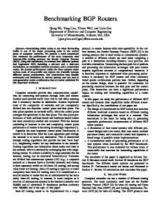
2.2 Design of DS Routers The Differentiated Service enabled routers (DSenabled routers or DS routers) are key nodes in the DiffServ model. There are two types of DS-enabled routers: (1) edge routers, and (2) core routers. In this work, we focus on the design and implementation of the edge routers. Figure 1 shows the structure of a DS router.
Pb
0
Tmin_b
Tmax_b
Pa
Tmin_a
Tmax_a
Queue Length
Figure 2: RIO Queueing Discipline Meter (Token Bucket / Leaky Bucket)
Classifier
Marker / Remarker
Queueing Disciplining PS-queue / RIO-queue
multi-class Random Early Detection (RED) algorithm which the RIO-queue is using. When RIOqueue length exceeds the dropping threshold � ��
� , new best-effort packets are dropped with increasing probability up to ��� . When RIO queue length exceeds � ��
� , new assured packets are dropped with increasing probability up to ��� . When queue length exceeds � ����� � , all new best-effort packets are dropped. When queue length exceeds ������� � , all incoming packets are dropped. By tuning the values of � ��
� , � ��
� , � ����� � , � ����� � , � � and � � , we can expect different dropping behaviors for both best-effort and assured packets.
Shaper
Dropper
Figure 1: The Structure of a DS Router In the figure, there are several key components to the DS router structure:
� The Classifier.
The Classifier classifies packets according to their DSCP in the IP headers.
� The Meter. The Meter performs in-profile / out-of-
�
profile checking on each incoming packet. Because burstiness exists in assured class traffic, the token 3 Implementation bucket scheme is used to check the conformance of assured class traffic. While the leaky bucket scheme The simulation is implemented using OPNET Modeler is used for premium class traffic, since burstiness is 6.0.L running on Windows NT 4.0 Workstation with dual PentiumPro 200Mhz CPU and 128MB of RAM. Figure 3 not allowed in premium class traffic. shows the topology and scale of the simulation environThe Marker/Re-marker. After being classified, pack- ment. The “clients” subnet comprises three client nodes, ets are marked into premium, assured and best-effort one switch and one DS edge router. The “INET CLOUD” classes accordingly. Re-marking happens when as- consists of three DS-enabled / non-DS-enabled routers (it sured packets violate the contracted traffic rate limit can be expanded to a more complicated topology). The and become out-of-profile. These packets are re- “servers” subnet contains one server and one edge router. marked as best-effort packets.
� The Dropper/Shaper. If premium packets become
1 Random Early Detection with distinction of In-profile and Out-ofprofile packets [1]
out-of-profile, they are dropped immediately by the 2
IP_servic
50
(PK_READY)
(SERVICE_NEW_PK)
(SERVICE_QUEUED_PK)
(NO_DIFFSERV) init
init_too
DS_schd
svc_start
svc_compl
45
(default)
(ARRIVAL) (SELF_NOTIFICATION)
(default)
(DIFFSERV)
(DS_SCHD)
40 clients
(default) wait INET_CLOUD
cmn_rte_tbl
arrival
(SELF_NOTIFICATION)
idle
(SVC_COMPLETION)
(ARRIVAL)
35 servers
(default)
30
(RECEIVE_PACKET) enqueue
25
init -125
-120
-115
-110
-105
-100
-95
-90
-85
-80
-75
-70
idle
-65
extract (SEND_PACKET)
OR 44
38.5
client0
41
43.5
Figure 4: The Process Model for a DS Enabled IP Module
38
40.5 switch0 E_router_0 43
router_0
client1
router_1
router_2
� Initializations.
server
E_router_1 37.5
All the initializations are done through “init”, “wait”, “cmn rte tbl” and “init too” states sequentially, which is the same as what the original OPNET IP process model does.
40
42.5
37
client2 -120.5
-120
-119.5
-119
-101
-100.5
-100
-83
-82.5
Figure 3: Network Topology for the Simulation
� DS and non-DS-enabled states. If the node is set to be DS-enabled, the transition labelled with “DIFFSERV” condition occurs. Otherwise, the transition labelled with “NO DIFFSERV” condition occurs. The reason we design the model to handle both DSenabled and non-DS-enabled cases is described in Section 3.3, Problem I.
3.1 DS router To implement the DS scheme in a router, we have two options to choose from. One is to implement the DSenabled IP module from scratch. The other one is to modify an existing router implementation available from the OPNET vendor’s library. In our simulations, we choose to modify the existing OPNET model for Cisco 7204 router. We make this decision based on the fact that most components needed for our DS-enabled router exist in the Cisco 7204 router model. Only the IP process model needs to be modified in order to handle traffic from different classes. Therefore, we modify the IP module and put DS components in it. Although making the router DS-enabled is a significant enhancement with respect to functionality, the overall structure of the router has not been changed a lot. The reason is that in OPNET different modules (e.g., MAC, IP, TCP, OSPF, RIP and so on) are implemented as separated objects, which communicate with each other through modular interfaces. As long as our DS-enabled IP module maintains proper interface, it can swapped into the router model, and the lower and higher protocol layers are able to communicate with the new IP process module properly. Figure 4 illustrates the process model for a DS enabled IP model. There are two different processes in our implementation. The top one diff ip rte v4 model is the main IP process, which implements main IP and DiffServ functionalities. And the lower one diff pq model is the child process, which implements priority scheduling scheme for DiffServ. The IP diff ip rte v4 process model is implemented as follows:
� Packet Classification. The packet classification is implemented in the “DS schd” state.
� Packet Monitoring and Policing. Packet monitoring and policing are implemented in the “DS schd” state. After being classified, an incoming packet is monitored and policed according to the class it belongs to. If the packet is a premium class packet, it is monitored and policed by using the leaky bucket model. If the packet is an assured class packet or a best-effort class packet, it is monitored and policed by using the token bucket model (Section 2.2). If the packet is in the premium class and is conformed (in-profile), it is processed by the next state, the “IP serv” state, directly. If it is non-conformed (out-of-profile), it is discarded without any further process. If the packet is an in-profile assured packet, it is processed by the “IP serv” state, otherwise it is re-marked as a “best-effort” packet in “DS schd” state and processed by “IP serv” state later. If the packet is a “best-effort” packet, it goes ahead into the “IP serv” state and gets processed there.
� Packet Routing and Forwarding. After the classification and the conformance check, the packet enters the regular IP forwarding process, which is implemented by “IP serv”, “srv start”, “srv compl” 3
and “idle” states. All of these states are implemented based on IP states provided by the OPNET library, except that the “idle” state is DiffServ-aware. 2
If ( packet is premium ) then if ( current size of the leakybucket + packet size token bucket depth ) then on premium class traffic and assured class traffic, available tokens = token bucket depth; endif respectively. The reason behind this is that for preif ( available tokens < the packet size ) then re-mark the packet as a best-effort packet; forward this packet to the next state; mium class traffic, the resource reservation is done else forward this packet to the next state directly; based on the peak rate, thus we do not allow any burst residual tokens = available tokens - packet size; endif rate which exceeds this reserved rate. While for the last service time = current time; endif assured class traffic, the reservation is based on the statistical guaranteed rate, thus a certain amount of bursts are allowed. How many bursts are allowed in Figure 5: Algorithm to Implement the Leaky Bucket and the system is determined by the token bucket depth. the Token Bucket Figure 5 shows the implementation. To calculate the token availability, instead of scheduling a selfpackets waiting in the PS-queue are serviced before interrupt for each time unit, we do the calculation any packets from the RIO-queue. only at the time a packet is arriving, which is more efficient. For a premium packet, we hold it in the � PS-queue. The PS-queue is implemented as as a bucket until it gets enough tokens. If the bucket is FIFO queue. If the queue overflows, the incoming overflowed, the packet is discarded directly. For the packets are discarded. Actually, the overflow case token bucket, we keep track of two time variables: rarely happens, since all the premium packets are the current time ( ����� ��� �"! ) and the last service time monitored and shaped before they enter this node. ( #%$'&(� &*)+� ��� �"! ), which are used to calculate the � RIO-queue. The RIO-queue is more complicated available tokens. When an assured packet comes, the token bucket first updates its available tokens, than the PS-queue. It adopts the multi-class RED algorithm (Section 2.2). In our implementation, $,)+$,� #-$'.�#%! �0/21'!435&768�0/219!(3 �:$,�0!�;=� ��� �"!,? all parameters of the algorithm are implemented as “attributes” in the node interface (e.g., PS-queue #-$'&*� &()+� ��� �@!:ACBD�E!:&(��FG��$+# �0/21'!435& size, RIO-queue size, thresholds for assured and best-effort traffic to begin dropping, and so on). The If there are enough tokens to be dispensed for the user can tune these parameters, resulting in different current packet, the packet will be forwarded to the dropping behaviors for the assured packets and bestnext state; otherwise the packet is re-marked as a effort packets (Figure 2). best-effort packet and then forwarded to the next state. The child process diff pq handles priority packet 3.2 Traffic Sender and Receiver scheduling by using two queues: the PS-queue for the We use the “Video Conferencing Transport” as the appremium class traffic, and the RIO-queue for the assured plication for our simulations. It uses UDP as the transport and best-effort traffic. The child process is implemented protocol and is provided by OPNET. The scenario for as follows: the regular “Video Conferencing Transport” is: (1) the client (traffic sender in our case) sends UDP traffic to the � Process Model. The child process model is shown server at a constant rate; (2) the server (traffic receiver in Figure 4. If no packet is coming and no packet is in our case) echos the traffic back to the sender at the being scheduled, it is in the “idle” state. When a new same rate. In our simulation, we modify the server so packet comes, it enters the “enqueue” state where that the echo is disabled, making it a pure traffic sink. the PS-queue and RIO-queue are implemented. The The sending rate at the traffic sender can be tuned for incoming packet is put into the appropriate queue different simulation cases. In the traffic receiver, we with respect to its service class. The PS-queue has add a monitoring module into its “ip encap” process. It higher priority over the RIO-queue. Therefore all provides three local statistics (“premium rate”, “assured 2 Besides the conditional transitions “ARRIVAL” and rate”, and “best-effort rate”) in its interface. These three “SVC COMPLETION”, “DS SCHD” transition is added. local statistics keep track of the receiving rate of the 4
premium traffic, the assured traffic, and the best-effort traffic, respectively. The reason it is put in the “ip encap” layer instead of the “application” layer will be discussed in Section 3.3, Problem II.
does receive data. We realize that this is because of a thrashing phenomenon. At the sender’s side, a packet with large size is fragmented into multiple IP packets in the IP layer during transporting. In case of traffic congestion, some or all IP fragments are dropped. Even if one IP fragment gets dropped, the receiver side IP is unable to re-assemble the packet, resulting in the drop of the whole IP packet. To solve this problem, we can use small packet size (e.g., less than 1,500 bytes/packet). But considering some special cases where a large packet size may be used, we move the monitoring and reporting module down to the “IP encap” layer in order to get more accurate IP statistics for different service classes. The simulation results show that it solves the problem.
3.3 Problems and Solutions During the implementation and simulation, we have encountered two problems.
� Problem I. Our simulation environment includes both DS-enabled nodes and non-DS-enabled nodes, which is a natural scenario in the real Internet. Therefore both DS-enabled IP module and nonDS-enabled IP module are used in the same simulation. For example, the traffic receiver uses non-DS-enabled IP module, while the backbone routers use DS-enabled IP modules. But we always get compilation errors when we try to use both IP modules simultaneously. It seems OPNET defines some internal global variables for the IP modules (e.g., routing table export file created, routing table import export flag, and so on). Since our DS-enabled IP module is based on the regular IP module, if both DS-enabled and non-DS-enabled IP modules are used simultaneously, “variables redefined” compilation error messages are given. To solve the problem, we make our IP implementation, the diff ip rte v4 model, flexible enough to accommodate both DS-enabled and non-DS-enabled IP modules. In the user interface, we provide an attribute called ip.diffserv flag. The default value is 0, which means the node is non-DS-enabled. The node runs as a DS-enabled router if user sets the ip.diffserv flag to 1. As illustrated in Section 3.1, there are two paths from the “arrival” state to the “IP serv” state within the diff ip rte v4 model (Figure 4), one for DS-enabled nodes and the other for non-DS-enabled nodes. Upon a packet’s arrival, an appropriate path is chosen with respect to the value of ip.diffserv flag. Results show that it does solve the problem.
4 Simulations and Results In the sections above, we introduced our DS router design, implementation and simulation configuration. In this section, we will give the detailed description to our simulation cases and their results. Although we have more experiments and results, we can only present two cases of them here due to space limitation. Throughout this section we will use parameter settings shown in Figure 6 for both simulation cases. Key Parameters
Case I
Case II
PS-queue size (Bytes)
10,000
20,000
Queue size (Bytes)
8,000
20,000
Pa / Pb
0.5 / 1.0
RIO-queue
Ta0 / Ta1 / Tb0 / Tb1 Premium traffic
Sending rate (Bytes/s) Period
Assured traffic Best-effort traffic Leaky Bucket
Token Bucket
0.8 / 1.0 / 0.5 / 0.75 _____ _____
0.5 / 1.0 0.8 / 1.0 / 0.5 / 0.75 150,000 40s ~ 1m20s
Sending rate (Bytes/s)
150,000
150,000
Period
30s ~ 1m35s
40s ~ 1m20s
Sending rate (Bytes/s)
20,000
200,000
Period
20s ~ 1m50s
20s ~ 1m50s
Token rate (Bytes/s)
150,000
50,000
Bucket depth (Bytes)
200,000
200,000
Token rate (Bytes/s)
50,000
50,000
Bucket depth (Bytes)
500,000
200,000
Figure 6: Simulation Parameter Settings
� Problem II. Originally, we put the monitoring and reporting module in the “application” layer in the traffic receiver, which monitors and reports the receiving rates of the three class traffics. But a problem occurs when we use large packet sizes for the video conferencing traffic. When we use a large packet size, such as 10,000 bytes/packet, we get nearly nothing at the receiver side, which means the recorded receiving rates for all three classes are approximately equal to 0. But the statistic recorded on the Ethernet link at the receiver side shows the node
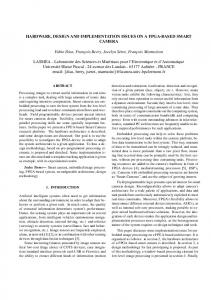
4.1 Case I - Verify the Service Differentiation The parameter settings for this simulation case are shown in Figure 6. This case is designed to verify the service differentiation is correctly implemented. Traffic belonging to all the three service classes are injected into the network. The left hand side graph of Figure 7 shows the result with regular routers. It is clear that there is no differentiation between traffics. All traffics have to 5
90
90
75
75
60
60
45
hand side graph, we show the token bucket result. Notice the sudden jump for the assured rate at 0m40s. This is due to that the token bucket is full at the beginning of the assured traffic. We call it the “Token Bucket Effect”, which verifies that the token bucket can allow certain amount of bursts. Accordingly, the sudden drop of the best-effort rate is due to the sudden jump of the assured rate. The graph also shows that the assured rate is bound to the token rate 50,000 bytes/s, verifying that the token bucket works well. In the right hand side graph, we show the result of the leaky bucket. Since the leaky bucket does not allow any burst, there is no sudden jump or drop in the graph. The premium rate is bound to the token rate 50,000 bytes/s, verifying that the leaky bucket works well too.
45
30
30 client0 client0
router_0 router_0 router_2 router_2
15
15
0 -120
-90
-75
switch0 -60 switch0 -45
-30 -15 0 E_router_0 E_router_0
15
30
0 45
60
75
client1 client1
90 105 120 E_router_1 E_router_1
135 server 150 165 server
180
Figure 7: Service Differentiation between Service Classes (Left: non-DS router results. Right: DS router results) router_3 router_3
router_1 router_1
client2 client2
contend the T1 bandwidth. The right hand side graph of Figure 7 shows the result with our DS-enabled routers. It shows clearly that the premium traffic has the highest priority and its rate is guaranteed with the expense of dropping assured and best-effort rates (from 30s through 1m, The premium rate remains 100,000 bytes/s without any degradation). During the interval from 1m through 1m30s, where there is no premium traffic, the assured traffic has a higher priority than the best-effort traffic. Its rate is guaranteed with the expense of dropping the best-effort rate. After 1m30s, both premium and assured traffics shut down. The best-effort traffic grabs all the T1 bandwidth from then on. This test case shows clearly that our DS-router implementation complies with the DS principle and our design.
5 Conclusion In this paper, we introduced the design and implementation of DS-enabled routers in the Internet under the OPNET simulation environment. We also conducted a large number of simulations based on our DS-enabled routers. Through these simulations, we not only verified the correctness of our design and implementation, but also studied some DiffServ QoS features in a large scale network, such as priority dropping, QoS guarantees, token bucket effect, and so on. Moreover, we introduced some problems we encountered during our study and their solutions. We hope that our DS-enabled router can help further DS study.
4.2 Case II - Verify the Leaky Bucket and Token Bucket Scheme client0 client0
router_0 router_0 router_2 router_2
15
15
0
References
0
switch0 switch0
server server
E_router_0 E_router_0
-15
E_router_1 E_router_1
-15
client1 client1
-30
-30
[1] Roland Bless and Klaus Wehrle. Evaluation of differentiated services using an implementation under linux. In IWQoS’99, London, 1999.
router_3 router_3
-45
router_1 router_1
client2 client2
-60
-60
-75
-75 -120 -90
-45
-90
-75
-60
-45
-30
-15
0
15
30
45 -90
60
75
90
105
120
135
150
165
180
[2] R. Braden and L. Zhang. Resource ReSerVation Protocol (RSVP) - Verion 1 Functional Specification. RFC 2205, September 1997. [3] S.Blake et. al. An Architecture for Differentiated Services. RFC 2475, December 1998.
Figure 8: Test the Leaky Bucket and the Token Bucket (Left: token bucket. Right: leaky bucket)
[4] S.Shenker et. al. Integrated Services in the Internet Architecture: an Overview. RFC 1633, June 1994. The parameter settings for this simulation case is shown in Figure 6. Figure 8 shows the results of testing the [5] F.Baker, D.Black, S.Blake, and K.Nichols. Definition leaky bucket and the token bucket. In this simulation, of the Differentiated Services Field (DS Field) in the we inject the best-effort traffic as the background load IPv4 and IPv6 Headers. RFC 2474, December 1998. at the rate of 200,000 bytes/s. Since the bandwidth of T1 link can hold only 190,000 bytes/s, both graphs in [6] K.Nichols, V.Jacobson, and L.Zhang. A Two-bit Differentiated Services Architecture for the Internet. Figure 8 shows that the actual maximum rate for bestRFC 2638, July 1999. effort traffic is little lower than 200,000 bytes/s. In the left 6