TELKOMNIKA, Vol. 11, No. 8, August 2013, pp. 4414~4421 e-ISSN: 2087-278X
4414
Design of an Integrated Controller based on ZigBee Wireless Network Zhongbao Ji Wenzhou Vocational and Technical College, Wenzhou 325035, China Tel: 0086-577-86680074 e-mail:
[email protected]
Abstract There are many different home appliances in our home, for example Lamps, Television, DVD player, etc. Moreover, the appliances are usually controlled by different controller using IR (Infra-Red) signal. This brings our life many inconveniences, and many resources are wasted. Therefore, we propose an integrated controller. It can control these various appliances, only a single one. In order to realize the purpose, the integrated controller must have previous preparations, because the appliances have their different IR controlling signals. Therefore, the integrated controller must “learn” the IR signals from their own controllers, and save them inside. Because the radiation range of IR signal is limited, and the appliances are distributed in different rooms, we propose a novel wireless network based on IEEE802.15.4, especially ZigBee protocol, to transmit the controlling signals from the integrated controller. The proposed scheme consists of two main parts. The one part is the hardware design, include the integrated controlled with ZigBee transmission device and the terminal control module with ZigBee-IR conversion, which converts a control signal transferred through the ZigBee network into an IR typed control signal. The terminal control module is based on CC2430 as the controller core. The other is the software design. The software part uses IAR Embedded Workbench. Based on Zstack-1.4.2-1.1.0 protocol provided by TI, man can program the control codes of the system. The proposed scheme can also provide the welldefined interface and the necessary basis for preparing the smart home system. Keywords: integrated controller, ZigBee, IEEE802.15.4, CC2430, WPAN Copyright © 2013 Universitas Ahmad Dahlan. All rights reserved.
1. Introduction There are presently many home appliances in digital home environments, most of which are controlled by IR signal from their own remote controller. However, when we want to control these home appliances, we must first find their own controller. This brings our life many inconveniences and causes some resources are wasted. Therefore, we propose an integrated controller in this paper, which can control all appliances based IR signal. In order to realize the purpose, the integrated controller must make some previous preparations because every digital appliance hat different type controlling IR profile, for example leader code, control code, carrier frequency, etc. Therefore, the integrated controller must “read” the information from the relative controller, and save it inside. Additionally, IR signal hat another shortcoming, the radiation range. It can only be transferred in LoS (Line of Sight) range. We propose a novel wireless network based on IEEE802.15.4, especially ZigBee protocol, to transmit the controlling signals from the integrated controller. The method is not only clever and expedient, but also hat easy installation and convenient maintenance. Wireless sensor network is a novel technology of obtaining and processing information, which is composed of many distributed notes, which have sensing, computing and communicating abilities. So it is widely used in environmental protection, medical and health, military application, smart space fields. ZigBee is a very important communicating and networking technology in wireless sensor network. ZigBee is a specification for a suite of high-level communication protocols based on an IEEE 802.15.4 standard for wireless personal area networks (WPAN) [1]. ZigBee hat the following features: low-cost, low power, large network capacity, high security and low transmission rate, etc. The low-cost allows the technology to be widely used in wireless control. Low power usage allows longer life with smaller batteries. Short-distance allows building WPAN.
Received January 14, 2013; Revised May 13, 2013; Accepted May 22, 2013
TELKOMNIKA
e-ISSN: 2087-278X
4415
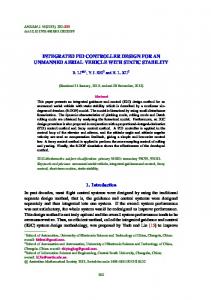
However, ZigBee is not a completely new technology and protocol. Its physical layer, MAC (medium access control) layer and data-linker layer are defined in IEEE802.15.4-2003. ZigBee Alliance defines network layer and application layer. The following Figure 1 shows architecture of ZigBee Protocol. IEEE802.15.4-2003 specifies 3 radio bands; 868 MHz in Europe, 915MHz in the USA and Australia, and 2.4GHz in most jurisdictions worldwide. Data transmission rates vary from 20 to 900 kilobits/second [2].
Application Layer
Customer
Application Profile Application Framework
ZigBee Alliance
Network Layer Data-Linker Layer MAC Layer
IEEE802.15.4
PHY Layer
Figure 1. Architecture of ZigBee Protocol
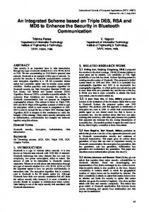
When a device unit in ZigBee network is independently able to work, it can be called node. ZigBee network consists of Coordinator node, Router nodes, End-Device nodes. ZigBee Coordinator and Router are Full Function Device (FFD), while End Device is Reduced Function Device (RFD). Coordinator node has the strongest function in ZigBee network, is responsible for initializing, maintaining and controlling the whole network. When using encrypted communication, it is the Trust Center of ZigBee network, manages joining new nodes, and allocates secret keys. Router node is a relay node of network, is responsible for forwarding information, and allows new nodes to join in the network. End-Device node can only communicate with its related router node, but not forward information to other nodes. In addition, it can intermittently sleep to save energy. 2. Hardware Design and Implementation of the Integrated Controller 2.1. Related Previous Preparation Works Along with economic development and improvement of living standard, more and digital appliances move into people’s life. In order to expediently control them, man adopts IR remote control mechanism, because it is the cheapest mode in LoS (Line of Sight) range. At present, there are many different communication protocols in the world, for example ITT Protocol, NEC Protocol, Nokia Protocol, etc. We take NEC protocol as an example, which frame structure stream is shown in Figure 2. In Figure 2 we can see, a typical pulse train of the NEC protocol consists of a 9ms AGC burst, Address and Command, which are transmitted twice to guarantee the transmission quality. We can classify the IR control stream into two major components, carrier and control signal parts. The carrier signal is to transfer an IR control stream with a specific frequency, otherwise the control signal part is to define the value, being specified with logic ‘1’ and ‘0’, for each field [3, 4]. In this paper, we propose a novel integrated controller to manipulate all home appliances. Nevertheless, in actual operation there are some difficulties. The reason is that each appliance hat its own IR remote control signal, for example carrier frequency, lead code, signal definition for logic ‘1’ or ‘0’, etc.
Design of an Integrated Controller based on ZigBee Wireless Network (Zhongbao Ji)
4416
e-ISSN: 2087-278X
Figure 2. Typical Frame Structure IR Stream of NEC Protocol
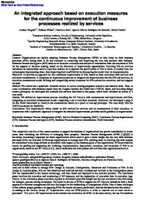
In these times, more and more different home appliances move into our digital home environment. As everyone knows, they are controlled and managed by IR remote control with their own carrier frequency, lead code and definition for ‘1’ and ‘0’. Additionally, these appliances are distributed in different rooms. In order to control them with only one integrated controller, we must complete two works. First is that the integrated controller must have previous preparations, for example, that the integrated controller must “learn” the other IR signals from their own controllers, and save them. Second is how we can control other appliances in other rooms with the integrated controller based on IR signal. Usually we choose one of wireless network technologies, for example Wi-Fi, Bluetooth, ZigBee, etc. In this paper, we adopt ZigBee technology, because of the advantages as described in above section. Through building a WPAN based on ZigBee, controlling messages from the integrated controller are transmitted into other rooms. In Figure 3 shows the whole architecture in smart home system.
Room 3
Room 4 The integrated controller
Room 1
Figure 3. The Whole Architecture in Smart Home System 2.2. Related Hardware Design Work The hardware implementation includes two main patrs. One is the building ZigBee network, which transmits the controlling messages. The other is the integrated controller and the ZigBee-IR modules, which can convert the ZigBee signals to IR signals. Figure 4 shows the whole system configuration. In this figure, the integrated controller is the controlling signals generator of the whole system. Based on ZigBee technology, the smart-home wireless control network consists of EndDevice (RFD) installed in ZigBee-IR modules, controlling and monitoring center (FFD) and wireless network system (Router). The End-Device (RFD) contains communication controller system and DC power, etc. By the automatical routing function of Routers, the system can build the communication between Routers and RFD nodes to implement the wireless automatic control of smart home system. TELKOMNIKA Vol. 11, No. 8, August 2013: 4414 – 4421
TELKOMNIKA
4417
e-ISSN: 2087-278X
Z-IR
Access Network Interface
ZC Z-IR
Dev2
Integrated Controller
ZD Wired Or Wireless
Dev1
Home Server
Z-IR
Dev3
Based on IEEE 802.15.4
Z-IR
ZD
ZigBee Device Function
ZC
ZigBee Coordinator Function
Z-IRConversion
Dev4
from ZigBee to IR
Figure 4. System Configuration to Control Home Appliances based on ZigBee Network
This network has a coordinator what controls the monitor system. The coordinator manages the network, displays the net-working information and the working state of smart home system and controls the switching state of the whole network. And the system has also some Routers, that work as the relay controller of wireless nodes for the remote control. Meanwhile, the Routers are used as RFD nodes, too. Additionally, the system has many End-Devices, that receive only the wireless signals from WPAN to control the working state of WPAN. ZigBee supports many network tepology structures: star and tree typical networks, and generic mesh networks, etc. Because the system is used in home environment, it adopts starnetwork structure, shown in the following Figure 5.
Coordinator (FFD)
Router (FFD)
End Device (RFD)
Figure 5. Architecture of WPAN in this Work
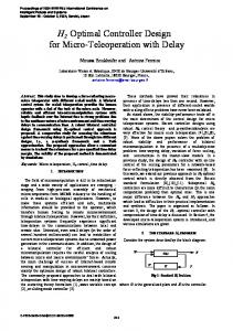
The network hardware adopts the wireless transceiver-CC2430. It is developed by Chipcon company in Norway. It is a true System-on-Chip (SoC) solution for 2.4GHz IEEE802.15.4. It has the following characteristics: low power, high receivering sensitivity, strong anti-interference, etc. It integrates ZigBee Radio-Frequency (RF) front-end, memory and microcontroller. It uses a 8-bit Microcontrolunit (MCU)-8051, and has 128Kb programmable Flash and 8Kb RAM. Additionally, it has also 14 bit Analog-to-Digital Converter (ADC), 4 Timers, Watch-Dog timer, and 21 programmable I/O pins [5]. CC2430 needs only few peripheral components to build a hardware circuit. Its peripheral components include the two parts, one is crystal clock circuit, the other is RF Input/Output matching circuit. The intrinsinc signal of the chip is provided by external activepower crystal, or internal circuit. The RF Input/Output matching circuit has a main purpose to match the Input/Output resistance of the chip. Meanwhile, it can provide the DC bias for internal PA and LNA of the chip. The CC2430 hardware circuit is shown in the figure 6. The circuit adopts a nonequilibrium antenna, what connects a nonequilibrium transformer to improve the Design of an Integrated Controller based on ZigBee Wireless Network (Zhongbao Ji)
4418
e-ISSN: 2087-278X
performance of the antenna. The nonequilibrium transformer consists of capacitor C341, inductor L341, L321, L331 and a microwave transmission line. The whole circuit can meet the requirement, that the RF Input/Output matching resistance is 50 . R221 and R261 are the diverging resistance. R221 works for providing a suitable current for 32MHz-crystal oscillating circuit. This oscillating circuit consists of a 32MHz-quartz crystal (X1) and two capacitors (C191 and C211). A 32.768KHz quartz crystal (X2) and two capacitors (C441 and C431) compose a 32.768KHz crystal oscillating circuit. The voltage regulator supplies power for all demanding 1.8V pins and internal circuit. C241 and C421 are decoupling capacitor, that realize supply power filter to improve the stability of the chip. In order to reduce the external interference and improve the performance of RF, the anti-interference measures must be implemented for the design of analog part. For example, magnetic bead or inductor is added for the analog power; the analog grounds and the digital grounds are separately; the filter capacitors are as much as possible close to the chip; etc. VDD VDD 1.8V
C311
C271
C251
AVDD-IF1
AVDD-CHP
AVDD-RF2
AVDD-ADC
AVDD-ADC
37 AVDD-IF2
C361
L321
RREG-OUT
40
39
38
AVDD-ADC
DVDD-ADC
AVDD-DGUARD
C381 58P
36 AVDD-RF2 35 34 33 32 31 AVDD-RF1 30 29 28 27 AVDD-CHP 26 25 AVDD-IF1
AVDD-RF2 AVDD-SW RF-N TXRX-SWITCH RF-P AVDD-RF1 AVDD-PRE AVDD-VOC VOC-GUARD AVDD-CHP RBIAS2 AVDD-IF1 AVDD-RREC
RBIASI
X0SC-Q1
43
41 AVDDDREG
DCOUPL
AVDD-DREC AVDD-S0C
X0SC-Q2
44
42
P2-4/X0SC-Q2
P2-3/X0SC-Q1
45
P0-5
P0-7
46
48
47 DYDD47
P0-2
SK
P0-6
P2-2
P2-1
P2-0 R101
P1-7 P1-6 P1-5 P1-4 P1-3 P1-2 DVD D P1-1 P1-0 RESET-N P0-0 P0-1 P0-4
DVDD-7 VDD
DVDD
AVDD-S0C
1 2 3 4 5 6 7 8 9 10 11 12
C421
X2
AVDD-RF1
C431
C201
P0-3
C411 AVDD-DREG
DVDD-7
DVDD-47
C71
AVDD-RF2
C441 C471
L331
C341
L341
24
23
22
21
AVDDSOC20
19
18
17
16
14 TXD
15
13 RXD
R261 VDD VDD
X1 R221 C231 C191
C241
C221
Figure 6. Diagram of CC2430 Hardware Application Circuit
The coordinator of the wireless control system needs display the present network state. So the coordinator consists of CC2430, serialport part, keys and LCD. Its diagram is shown in Figure 7. RFD nodes and Router nodes consist of CC2430, serial extended interface, ZigBee-IR circuit, shown in the following Figure 8.
VDD
VDD
wireless part
wireless part R1 RF-P
P0-0
CC2430
P1-7
P1-6
P1-1
RXD
P0-5
S1 P1-5
MAX232
RXD
RF-N
TXD
P1-4
TXD
Confirm
R4
R3 5
RF-P RXD
4
TXD
3
VDD
RF-N
CC2430
2
S2 Cancel
1
R2
C1 D1
GND
UART
RST
SDO
CLK
CS
RS
R5
LCD
Figure 7. Diagram of Coordinator Circuit
Light-adjusting control
R6
Figure 8. Diagram of RFD and Router Circuit
TELKOMNIKA Vol. 11, No. 8, August 2013: 4414 – 4421
TELKOMNIKA
e-ISSN: 2087-278X
4419
3. Software Program Design
In this paper, we adopt “IAP Embeded Workbench” development environment. And based on ZStack-1.4.2-1.1.0 provided by TI, the applicationprogram of the system is writed. ZStack provides also some application interfaces, for example aplFormNetwork(), aplJoinNetwork() and aplSendMSG() functions, etc. User can write their development and application program by calling these functions. 3.1. Software Flow During working of the system, the coordinator of the wireless network will periodically detect whether keys are pressed to implement the relevant power ON/OFF commands. When the coordinator is idle, it is able to monitor wireless signals in the air. Then it judges whether new nodes want to join in the network, and if yes, allocates new IP addresses for the new nodes. Its software flow chat is shown in Figure 6.
Initialization Establishing a new network
Display ID of network
Monitoring state
Whether new nodes join in?
Y
Allocating IP addresses for new nodes, display it
N N
Key pressed? Y Sending command, displaying the working state
Figure 9. Flow Chat of Coordinator
Router is usually in the monitoring state. If it receives the power-ON command, it executes the command, and decides to retransmit or not. Meanwhile, accoding to the present light intensity, it decides turn on or not home lamps. RFD nodes are easy. They receive only the commands from WPAN, and implement them. The software flows of the 2 kinds devices are seperately shown in Figure 7, Figure 8. 3.2. Establishing a Network In ZigBee network, the coordinator has the following functions: establishing a new network, allocating IP address, allowing the connect between MAC Layer and Application Layer, etc. After the initialization of the coordinator, it will call aplFormNetwork() to establish a network. The coordinator builds a network through scanning a empty channel. Then it chooses a random PANID to monitor the channel. The establishing-network program is shown: void main (void) { …… hallnit(); apllnit(); …… aplFormNetwork();
Design of an Integrated Controller based on ZigBee Wireless Network (Zhongbao Ji)
4420
e-ISSN: 2087-278X
while(apsBusy()) {apsFSM();} while(1) {apsFSM();} …… } 3.3. Joining in a Network After building a network, it is considered, how Router nodes and RFD nodes can join in the network. They can do it through calling aplJoinNetwork() function. They scan channels to find the coordinator. Then they obtain the IP address of the coordinator, and send their IP addresses to it. After joining in the network, the network nodes are in dormant state, until commands or data need be sent. The program of joining in a network is shown: void main (void) { …… hallnit(); apllnit(); …… do{ aplJoinNetwork(); while(apsBusy()) {apsFSM();} } while(aplGetstatus()=WXLPAN_STATUS_SUCCESS); while(1) {aplFSM();} ……}
Initialization
Initialization
Joining in the network
Sending the join-in signal
Monitoring state Join-in a network is ok?
Judging the received signal
Join-in signal
Y
Allocating ID of network, and display it
Monitoring state
Control signal Controlling the lamp switch, retransmitting to next
N
Implementing commands
Turning on/off the related switches to control the devices
Figure 10. Flow Chat of Router
Figure 11. Flow Chat of RFD
4. Result We test the network building delay of the system, data transmission rate, and the influence of communication distance to data transmission, etc. For single coordinator and single node, the using time of building network is 20s. For scanning 16 channels, the average using time is 150s. The using time in first time is longer, mainly because of waiting for beacon frames, determining the channel of the coordinator. Under the condition: ca. 10m indoor distance and no partition board, data transmission rate is 250kbps. In vacancy outdoor environment and distance between 35m and 70m, the rate is
TELKOMNIKA Vol. 11, No. 8, August 2013: 4414 – 4421
TELKOMNIKA
e-ISSN: 2087-278X
4421
40kbps. When the distance is 300m, the rate is 20kbps.Additionally, the working current of the system is 25.7mA (sending), and 29.3mA (receiving). When it is idle, the current is only 2.5μA. 5. Conclusion In this paper, we propose a novel integrated controller to control the different home appliances, instead of the traditional controllers. The scheme is based on IEEE802.15.4, especially ZigBee protocol. This work consists of two main parts, one is hardware design, and the other is software design. In the hardware field, there are two kinds of hardware parts to design and implement. One is the integrated controller, and the other is ZigBee-IR module. The integrated controller is the controlling signals generator of the whole system. The signals are transmitted in WPAN, based on IEEE802.15.4. The functions of the integrated controller can be expanded, for example controlling the home server, voice controlling, data-exchange with handy, etc. The ZigBee-IR module can convert the signal mode from ZigBee to IR, because the home appliances are controlled and managed by Infra-Red signals. Additionally, the scheme decreases the resource waste and cost of the system. The developed system has the following advantages: low power, low cost, easy installation, maintenance convenience, etc. So the scheme will be widely used, and provides the well-defined interface and the necessary basis for preparing the smart home system. References [1] IEEE Std 802.15.4 Wireless Wireless Medium Access Control (MAC) and Physical Layer (PHY) Specifications for Low-Rate Wireless Personal Area Networks (LR-WPANs). 2003. [2] P Baronti, P Pillai, V Chook. Wireless sensor network: a survey on the state of the art and the 802.15.4 and ZigBee standards. Computer Communications. 2007; 30: 1665-1695. [3] Intark Han, Hong-Shik Park, Youn-Kwae Jeong, Kwang-Ro Park. An Integrated Home Server for Communication, Broadcast Reception, and Home Automation. IEEE Transactions on Consumer Electronics. 2006; 52(1): 104-109. [4] Jin-Shyan Lee. An Experiment on Performance Study of IEEE 802.15.4 Wireless Networks. Proceedings of 10th IEEE Conference on Emerging Technology and Factory Automation. 2005; 2: 4511-458. [5] Bo-Teng Huang, Ko-Yen Lee, Yen-Shin Lai. Design of a Two-Stage AC/DC Converter with Standby Power Losses Less Than 1 W. Proceedings of Power Conversion Conference. 2007; 1630-1635. [6] Joon Heo, et al. Design and Implementation of Control Mechanism for Standby Power Reduction. IEEE Trans. on Consumer Electronics. 2008; 53(1): 179-185. [7] Jui-Yu Cheng, Min-Hsiung Hung, Jen-Wei Chang. A ZigBee-Based Power Monitoring System with Direct Load Control Capabilities. Proceedings of the 2007 IEEE International Conference on Networking, Sensing and Control, London, UK. 2007. [8] JD Lee, KY Nam, SB Choi, HS Ryoo, DK Kim. Development of ZigBee based street light control system. IEEE Power Systems Conference and Expoisition, PSCE’06. 2006; 1: 2236-2240. [9] Sensor Network Analyzer (SNA), http://www.daintree.net/products/sna.php#visualize [10] Niels Aakvaag, Mogens Mathiesen, Gilles Thonets. Timing and power issues in wireless sensor networks - an industrial test case. Processings of International Conference Workshops on Parallel Processing (ICPP). 2005; 419-426 [11] Zhenghua Xin, Hong Li, Liangyi Hu. The Research on CC2530 Nodes Communicating with Each Other Based on Wireless. TELKOMNIKA Indonesian Journal of Electrical Engineering. 2012; 11(1). [12] Qin Danyang, Wang Huiwu, Ma Lin, Ding Qun. Research on Topology Property for Wireless Multi-hop Communication Network. TELKOMNIKA Indonesian Journal of Electrical Engineering. 2013; 11(1).
Design of an Integrated Controller based on ZigBee Wireless Network (Zhongbao Ji)