Design Reuse
Virtual Simulation of Distributed IP-Based Designs Marcello Dalpasso
Luca Benini
University of Padova
University of Bologna
Alessandro Bogliolo University of Ferrara
JavaCAD, an Internet-based tool with a secure client-server architecture, lets designers perform functional simulation, fault simulation, and cost estimation of circuits containing IP components. It also ensures IP protection for both IP vendors and users, and provides seamless transition between IP evaluation and purchase. IN DESIGNING large-scale systems, design reuse can help bridge the productivity gap that threatens to slow down the pace of Moore’s law.1 Designers can take reusable blocks from internal libraries, or purchase them as IP components from third parties. The diffusion of IP components can radically change the traditional system design flow by separating the roles of ■ ■ ■
semiconductor manufacturers, who fabricate the chip; IP component developers, who design the basic building blocks; and system developers, who construct the finished product. To be fully successful, any IP-based design
92
0740-7475/02/$17.00 © 2002 IEEE
flow must address two major challenges: First, it must provide techniques that assess correctness and quality (in terms of area, speed, power, and testability) of designs containing IP components. Second, it must guarantee IP protection for both the vendor (IP provider) and designer (IP user). If the provider fully disclosed the IP component to the user, validating a design containing the component would be akin to validating a fully proprietary system. However, providers almost never grant full IP disclosure, because doing so would mean giving up the IP’s full value. Likewise, IP users do not want to fully disclose the content of their designs to IP providers. Hence, neither party ends up fully owning the information needed to carry out complete system validation. Before purchasing a component, the IP user wants a cost estimate of the area, speed, power, and testability of instantiating the component. During preliminary design exploration, approximate cost estimates, often available from standard data sheets, might suffice. But as the design is refined, the user might need far more accurate information. First, he might want an abstract functional model to test the component’s functionality within the design. Second, he might want accurate cost estimates, which he cannot obtain without at least partially knowing the component’s implementation and environment. The Virtual Socket Interface Alliance (VSIA) IEEE Design & Test of Computers
IP provider 1
IP user
Setup: Functional model 1 Power model 2 Timing model 2 Area model 0
Component 1
Component 2 Component 3 JavaCAD backplane (server)
User design JavaCAD backplane (client)
IP provider 2
Setup: Functional model 1 Power model 0 Timing model 0 Area model 0
Component 1
Component 2
Internet connection
Components 3, 4
JavaCAD backplane (server)
Figure 1. Internet-based client-server architecture of the JavaCAD design environment: design under development (a) and two IP component providers (b).
recommends that an IP component’s open specification should contain an executable functional model, precharacterized static estimates of the main cost metrics, and testing guidelines and patterns. However, protecting the provider’s IP limits the accuracy of any open specification. In this context, testability analysis is challenging, for two reasons: ■
■
A component’s testability depends on both its inputs’ controllability and its outputs’ observability in the design. No general, exact composition rules are available for estimating a design’s testability from its components’ testability.
Therefore, the VSIA testability directives are far more complex than those for any other cost metric. In particular, they recommend the use of DFT techniques or built-in self-test (BIST) architectures to preserve each component’s testability properties. Unfortunately, these techniques would involve significant costs in terms September–October 2002
of performance and area that are not always compatible with design budgets. JavaCAD, on the other hand, supports IP evaluation during design specification and exploration, while guaranteeing IP protection for both the user and the provider.2,3 Users can instantiate IP components from multiple remote providers and seamlessly simulate them with proprietary blocks.
JavaCAD architecture Figure 1 shows JavaCAD’s conceptual architecture. The user specifies a complete design within a JavaCAD client. The design contains IP components from one or more providers; these providers communicate with the client through JavaCAD servers. During simulation setup, the user and the providers negotiate the type of functional and cost models that will be available for each component. Some estimators and models might require a provider’s online intervention, possibly at an additional cost. For instance, users can accurately assess testability through a virtu-
93
Design Reuse
Related work Design based on IP requires communication of valuable information between IP providers and users. The definition of standard formats for design descriptions, such as VHDL and electronic design interchange format (EDIF), has been the first important milestone toward reusing EDA infrastructure in hardware design. Thanks to the growth of networked computing, new paradigms can organize access to design-specific information.1,2 The idea is to automatically collect and visualize geographically dispersed design-critical information (data sheets, technical documentation, and so on) by exploiting the Web. This idea has been very successful: Virtually all major semiconductor companies have Web servers that provide such information to designers.
Exploiting the Internet Several research groups have envisioned a more radical approach.3,4 They would exploit the Internet not only to share information but also to perform design-critical tasks, such as validation and optimization. In this more aggressive approach, a designer is a client in a clientserver architecture who can request services from various servers. CAD tool use is one type of service; IP delivery is another. More recent research initiatives propose advanced client-server architectures to support complex transactions and collaborative, distributed design.5,6 JavaCAD uses a client-server approach: IP users are the clients; IP providers are the servers. This is its main similarity with previous approaches. However, JavaCAD focuses more on supporting IP-based designs than on providing a distributed framework for generic EDA transactions. The current implementation uses Java as the hardware description language (HDL). Helaihel and
Olukotun have studied Java-based system specification styles,7 and they assess Java’s suitability as an abstract hardware-software description language. A new generation of IP-aware design tools for supporting IP-based design methodologies is under development. The main challenge for these tools is to enable design validation without compromising IP. A few approaches focus on IP provider protection. Watermarking protects the provider by embedding a digital signature into IP components: If users cannot remove the digital signature, then instantiating the component without the provider’s permission would be risky.8 In a court of law, the provider could prove that the component carries this signature. The main limitation of watermarking is that it only protects the provider from illegal instantiation of the component; it does not hide IP, and thus offers no protection against a dishonest user learning about the design through reverse engineering of the component architecture.
Model encryption An alternative, based on model encryption, protects a provider’s design secrets. A provider gives users an accurate simulation model encrypted to protect the provider’s IP. Users can then instantiate the encrypted simulation model and simulate it in their designs. Users receive the encrypted model as a precompiled object file that they can link to a simulator and run on their machine. However, using object code has two main challenges: ■
■
The object code is not portable, so the provider must prepare a different version of the encrypted model for each target architecture. Users must trust the object code enough to run it on their own machine.
al fault simulation of the entire design without providers disclosing the IP-protected components. Designers perform fault simulation, but whenever the JavaCAD client simulation engine requires some knowledge about an IP component’s implementation, the JavaCAD client asks the provider to perform these simulation subtasks. The JavaCAD backplane completely hides the complexity of the Internet communication between the client and servers. JavaCAD supports hierarchical descriptions, multiple abstraction levels, and distributed and
94
parallel simulation. Written entirely in Java, JavaCAD exploits Java’s object-oriented features to effectively map the component-based design semantics of modern digital systems, including full support for hierarchical designs at multiple abstraction levels. JavaCAD’s key feature is its ability to handle designs containing local (user owned) and remote (IP provider owned) components. In the current JavaCAD implementation, Java is also the modeling language. However, unlike other approaches described in the “Related IEEE Design & Test of Computers
Furthermore, model encryption protects only HDL descriptions of IP components, whereas IP information can be in a different form or at a different abstraction level. For instance, accurate power or speed estimation for a custom IP core might require a transistor-level, or even layout-level, view that is not available in the HDL description.
implementation cannot be accessed by a user. Using high-level fault models in this context would impair accuracy by disregarding valuable low-level information already available to the IP provider, even if the user cannot access such information.
References 1. M.J. Silva and R.H. Katz, “The Case for Design Using the
Testability issues
World Wide Web,” Proc. Design Automation Conf. (DAC
One of the key challenges in IP-based design is testability analysis and assessment. Designers hesitate to instantiate an IP component if they cannot obtain high coverage of its internal faults. Built-in self-test (BIST) architectures and DFT techniques can improve the testability of large IP-based designs but at the expense of large area, power, and speed overheads. Several recent approaches address testing issues at high abstraction levels. Research in this field stems from different motivations:
95), ACM Press, New York, 1995, pp. 579-585. 2. M.D. Spiller and A.R. Newton, “EDA and the Network,” Proc. Int’l Conf. Computer-Aided Design (ICCAD 97), IEEE Press, Piscataway, N.J., 1997, pp. 470-475. 3. L. Benini, A. Bogliolo, and G. De Micheli, “Distributed EDA Tool Integration: The PPP Paradigm,” Proc. Int’l Conf. Computer-Aided Design (ICCAD 96), IEEE Press, Piscataway, N.J., 1996, pp. 448-453. 4. D.B. Lidsky and J.M. Rabaey, “Early Power Exploration: A World Wide Web Application,” Proc. Design Automation Conf. (DAC 96), ACM Press, New York, 1996, pp. 27-32.
■
■ ■
Through simulation, high-level testing can verify a design’s functional correctness before performing low-level synthesis. Raising the abstraction level reduces the complexity of all design tasks. High-level models can steer design choices toward more testable solutions.
5. H. Lavana et al., “Executable Workflows: A Paradigm for Collaborative Design on the Internet,” Proc. Design Automation Conf. (DAC 97), ACM Press, New York, 1997, pp. 553-558. 6. F.L. Chan, M.D. Spiller, and A.R. Newton, “WELD: An Environment for Web-Based Electronic Design,” Proc. Design Automation Conf. (DAC 98), ACM Press, New York, 1998, pp. 146-151.
All of these approaches define high-level fault/error models that do not require any knowledge about the components’ inner structure. However, the issue raised by IP protection is slightly different. It is not about verifying design correctness before low-level synthesis. It’s about evaluating a design’s testability properties with IP components whose
work” sidebar, our contribution does not focus on modeling languages, and the choice of Java is not a key point for virtual simulation. We chose Java to exploit the tight integration between the Java development platform and the remote method invocation (RMI) protocol. This tight integration simplifies the implementation of our prototype virtual simulator. JavaCAD backplane The JavaCAD backplane is a set of packages written in Java, called JavaCAD Foundation Packages (JFP), which you can integrate in any September–October 2002
7. R. Helaihel and K. Olukotun, “Java as a Specification Language for Hardware-Software Systems,” Proc. Int’l Conf. Computer-Aided Design (ICCAD 97), IEEE Press, Piscataway, N.J., 1997, pp. 690-697. 8. A.B. Kahng et al., “Watermarking Techniques for IP Protection,” Proc. Design Automation Conf. (DAC 98), ACM Press, New York, 1998, pp. 776-781.
design environment. Both the IP providers and the IP user must use the JFP. Components and designs (hierarchical collections of interconnected components) are subclasses of basic JFP classes. Design specification requires the instantiation of JavaCAD classes that describe design components and are taken from either the standard JavaCAD packages, a userdesigned library, or IP libraries. Design validation and simulation involves invoking a Java virtual machine (JVM) to run the main JavaCAD class that implements the entire design under development.
95
Design Reuse
JFP contains a multilevel event-driven simulator. We chose this simulation engine because of the generality and flexibility of event-driven simulation, as opposed to more specialized simulation techniques, which target high efficiency at the expense of generality. Furthermore, JFP provides full support (based on Java threads) for concurrent simulations of different design parts or different setup environments for the same design. Finally, we conceived the entire JavaCAD architecture, with security as the main guideline, to protect the IP of component providers and users. Component and design specification Any design component in JavaCAD is a subclass of the ModuleSkeleton class, which implements the module interface. A ModuleSkeleton instance is specialized by ■
■
a set of methods executed when events reach the component (for instance, methods specifying functionality and evaluating cost metrics); and a set of ports, identifying the component connections; a port can be either bidirectional (providing both input and output connections) or oriented (providing only an input or output connection).
Designers can specify a module’s behavior at different abstraction levels. JavaCAD currently supports the gate and register-transfer levels, and we have devised an implementation at the behavioral level. The JavaCAD environment fully supports mixed-level system descriptions, with some design components specified at the RTL, and others at the gate level. Design modules can be either local or remote. Local modules always run on the IP user’s JVM; remote modules are accessible through the Internet. Some, or even all, of the methods of a remote module typically run on a JavaCAD server remotely located at the IP provider site. A connector ties two ports together and forwards events between modules. A custom connector can easily enforce any communication semantics between modules. For instance,
96
JavaCAD provides bit- and word-level connectors to handle gate- and word-level connections. You can design more complex connectors for abstract design representations, such as for video signals handled by a DSP. Because connectors represent point-to-point zero-delay connections, special modules are necessary to handle multiple fan-out nets and represent net delays. This feature gives designers a high degree of flexibility. For example, custom fan-out modules can provide different delays to propagate a signal toward different target connectors. Similarly, you can design custom modules to handle an interface between one part of the design specified at the gate level and another part described at the RTL. Simulation and event handling JavaCAD implements a general, multilevel, event-driven simulation engine that supports multiple event types. The superclass for any event is a token; a scheduler handles scheduling and delivery of all tokens. You can instantiate multiple schedulers and run them in concurrent Java threads; JavaCAD fully supports concurrent simulations running over the same design without any interference. During simulation, JavaCAD stores each component’s internal state information in lookup tables (LUTs), and unique identifiers associated with the schedulers address these LUTs. The scheduling mechanism cannot, even intentionally, cause interference between different schedulers, because a module can schedule a new token only when it receives one, and the newly created token is automatically joined to the same scheduler. JavaCAD doesn’t allow communication between schedulers, even though one simulation controller can launch and actively coordinate many cooperating schedulers. Tokens not only represent functional events (changes of signal values); they also provide a general communication paradigm to traverse the design, collect information from modules, set up runtime parameters, and so on. In other words, tokens implement a general messagepassing engine for design manipulation. Another useful feature of JavaCAD tokens and schedulers is the capability of modules to IEEE Design & Test of Computers
schedule events for themselves, implementing something like a self-trigger. This feature, for example, can easily implement autonomous components such as clock generators. Remote module implementation To implement remote modules, JavaCAD uses RMI, a JavaSoft implementation of a distributed-object model for Java. RMI retains the Java object model’s semantics, making distributed objects easy to implement and use. JavaCAD exploits the following key RMI features: ■
■
■
creation of local instances of remote classes (modules) without having their bytecode available—a situation typical of IP components; method invocation for remote classes, with proper handling of arguments and return values through object serialization; and a secure Internet communication channel between the client (IP user) and server (IP provider).
Remote modules need not be fully remote; in most cases, users implement as remote methods only methods containing IP-related information. An IP provider must design a special module by clearly stating which methods will be available for local downloads to the IP user, and which methods will be available through a remote Internet connection. After component development, testing, tuning, and compilation, the IP provider creates three main Java parts: ■
■
■
the public part, which the IP user must download and integrate in the design under development, contains the loadable bytecode of the component’s non-IP-protected methods (such as those that give the component functionality); the RMI stub, which the IP user must download, allows transparent access to the remote methods without any IP-protected information; and the private part, whose methods the IP user must invoke through the stub, always resides on the provider’s server. For example, in Figure 2 (next page), the IP
September–October 2002
provider can provide a local method (which will run on the IP user’s JVM) that accurately implements the multiplier’s functionality— abstractly expressed by a multiplication operation—without disclosing any IP. On the other hand, the IP provider should implement a method that returns accurate output timing information as a remote method. Accurate timing computation requires analyzing the multiplier’s gate-level structure, which cannot be disclosed to the IP user. Security and IP protection Security is a key issue in JavaCAD. The tight interaction between client and servers poses additional problems in traditional Internet-based client-server computing.4 In fact, the communication between client and server must be secure from third-party intrusions in an environment where even the client and server cannot completely trust each other, for IP protection goals. JavaCAD solves both problems by exploiting RMI features and creatively using the enhanced security model that comes in Java 2. For third-party intrusions, the RMI protocol transparently handles secure communication between the IP user and provider. This protocol uses customizable sockets for communication, which provide an agreed-to level of security between the client and server. JavaCAD implements security for the IP provider by splitting remote-module specifications into three parts, as previously discussed. The component specification’s IP-protected part resides at the IP provider’s server as a private class, whose bytecode never goes to the client. The IP user downloads the public part and uses it to instantiate the remote component within the design. The RMI stub invokes remote methods that run on the IP provider’s server on behalf of the IP user. Such a strict binding of the component’s IP-protected part to the remote provider’s server completely secures the IP component’s valuable information. Finally, JavaCAD protects the user’s IP when using remote components through careful argument marshalling in the RMI method invocation (object serialization). Bounding each module with connectors lets the JavaCAD engine completely inhibit the transmission of
97
Design Reuse
public class Example extends Design { public void design() throws Exception {
A
REGA
AR
int width = 16; Connector A = new WordConnector(width); Connector AR = new WordConnector(width); Module INA = new RandomPrimaryInput(width, A); Module REGA = new Register(width, A, AR); Connector B = new WordConnector(width); Connector BR = new WordConnector(width); Module INB = new RandomPrimaryInput(width, B, BR); Module REGB = new Register(width, B, BR); Connector O = new WordConnector(2*width); Module OUT = new PrimaryOutput(width, O);
MULT B
REGB
O
BR
(b)
JavaCADServer provider = new JavaCADServer("provider.Host.Name"); Module MULT = new MultFastLowPower(width, AR, BR, O, provider); Circuit c = new Circuit(INA, REGA, INB, REGB, MULT, OUT); SimulationController s = new SimulationController(c); /* put here the simulation setup */ s.start(); } } (a) Figure 2. Description of a JavaCAD class (a) and simple RTL design (b) for an operation to compute the product of two random 16-bit input words (stored in registers REGA and REGB). The IP user wants to use proprietary register macros (the registers are local modules) and evaluate a high-performance, low-power multiplier architecture sold by an IP provider (MULT is a remote IP component). The instantiation of a remote module is identical to the instantiation of any local module, but must cite an instance of the provider’s server in its constructor. The instantiation of the remote (virtual) multiplier can use parametric design macros on the provider’s side because the IP user passes the width of the input word as an argument to the multiplier constructor.
sensitive information about the other modules instantiated in the design, along with their properties and mutual relationships. Because the remote IP component, a module itself, needs only information available at its own ports to perform any possible estimation and simulation, JavaCAD transmits only this information over the RMI channel. In addition, the downloaded public and stub classes from the IP provider have no special permission when executing in the user’s environment, because JavaCAD marks them as nontrusted for proper handling by the Java security manager. For example, methods executed by such classes can neither read nor delete files on the user’s file system. The standard RMI security manager lets such methods communicate only with the provider’s server; the user can choose to relax security requirements.
98
Estimating cost metrics The JFP’s estimation package lets the framework perform static and dynamic estimation of cost and performance metrics (area, propagation delay, average power, peak power, I/O activity, and so on), called parameters in JavaCAD. An estimator evaluates a parameter’s actual value. Estimators have a unique name, an expected accuracy, a cost, and an expected CPU time. A given design component can have more than one estimator to evaluate the same parameter; Table 1 gives some simple examples. Users can trade off between accuracy, cost, and speed. Estimators can be either local (running on the user’s client) or remote (running on the provider’s server). This feature gives the virtual simulation—the early evaluation of a design comprising unpurchased IP components—a IEEE Design & Test of Computers
Table 1. Comparison of three estimators to evaluate the power consumption of multiplier MULT from Figure 2. Estimator
Average
Root-mean-
Cost per
CPU time
type
per pattern (s)
error (%)
square error (%)
pattern (cents)
Constant
25
90
0
0
Linear regression
20
50
0
1
Gate-level toggle count 10 20 0.1 100* * A flag tells the designer that communicating with the remote server across the Internet can require an additional, unpredictable amount of time.
degree of accuracy that requires the knowledge of undisclosed implementation details. The provider can release the first two estimators in Table 1 along with the IP component’s functional description. The third estimator in the table requires complete knowledge of the IP’s gate-level netlist, and so must run remotely on the provider’s JavaCAD server. The designer, in turn, should pay a fee to use the provider’s computation resources. IP user’s viewpoint From the user’s viewpoint, design evaluation involves two main steps: setup and evaluation. During setup, the user specifies which parameters to evaluate and which estimators each component must use. The user accomplishes this using a setup controller. This controller uses two main methods: set(, ), which specifies the criteria for choosing the estimator for a given parameter; and apply(), which hierarchically applies a setup to a module and to all its submodules such that the module is at the top of the entire circuit’s hierarchical view. If the user specifies the entire circuit (the top module) as the target for the apply method, JavaCAD applies the same setup criteria to all the components. If JavaCAD cannot satisfy setup requirements for a given component’s parameter, a warning message displays, and JavaCAD associates the default null estimator (which always returns a proper null value) with the parameter. Using the null estimator as a default has two main benefits: ■
It provides a simple way to perform partial estimates by specifying nonnull estimators only for the modules of interest.
September–October 2002
■
It enables the simulation of a design even if no estimators are available for some of its modules.
Evaluation proceeds during simulation, according to a given setup, which passes to the simulation controller constructor during instantiation. Multiple setups for the same design and multiple simulations performed concurrently on separate threads are both possible using different setups. Inside each module, a hash table, whose key is a setup controller, stores the relevant estimators. During event-driven simulation, the current setup always passes to the module with any simulation token, thus enabling runtime retrieval of the desired estimators and automatic invocation of the corresponding evaluation methods. IP provider’s viewpoint To make an IP component available in JavaCAD, the IP provider must provide a class for the component and an arbitrary number of classes for its custom estimators. The provider derives the component’s class from the JFP ModuleSkeleton class and by specializing the processInputEvent method, which implements the module’s functionality. All other methods (for initialization, event handling, setup control, estimator selection and invocation, and so on) come directly from the superclass and need not be overridden. Similarly, each estimator is a subclass of the JFP EstimatorSkeleton class, specialized by overriding the estimation method. After developing the estimators, providers must instantiate them within the IP component’s constructor for them to become candidate estimators for some of that component’s parameters. The module’s addEstimator method can serve this purpose.
99
Design Reuse
Table 2. JavaCAD simulation results for 100 random patterns with a buffer of five patterns, all performed on a Sun UltraSparc 1 running Sun OS 5 with Sun JDK 1.2. In all cases, the reported time does not include the time spent for the actual PPP estimations; this time would be extremely large with respect to the JavaCAD runtime and can safely be considered constant.
Design
Host
CPU time (s)
Real time (s)
All local
NA
13
15
Estimator remote
Local
14
21
Multiplier remote
Local
38
87
Estimator remote
LAN
14
32
Multiplier remote
LAN
38
65
Estimator remote
WAN
14
168
Multiplier remote
WAN
38
407
Performance analysis We base the case study presented here on the simple circuit shown in Figure 2, for three different scenarios: ■ ■ ■
All local (AL). All design components are local. Estimator remote (ER). Only one method of the multiplier is remotely accessed. Multiplier remote (MR). The entire multiplier is remotely accessed on the IP provider JavaCAD server.
JavaCAD does not perform power estimations at each pattern. Instead it buffers the input patterns to the multiplier (locally in the ER case, and remotely in the MR case) and issues them to the simulator with a configurable buffer size. Furthermore, gate-level simulation runs are nonblocking; they use a new thread. Buffering helps amortize the time spent on RMI calls and argument passing. Nonblocking simulation contributes to hiding the latency that long runs of the accurate gate-level simulator would cause. Table 2 reports the CPU and real times for the simulation of 100 random input patterns to the circuit for the three different scenarios. We simulated the remote cases (MR and ER) in the following network environments: ■
■
■
The AL case is used for comparison and regards a classical design with no IP protection. The ER case involves an accurate power estimation with PPP,5 an advanced gate-level power simulator based on Verilog-XL as a simulation platform. The Java Native Interface (JNI), which links a C library and calls the PPP simulator, lets JavaCAD invoke the PPP simulator. Running this simulator requires a gatelevel description of the IP-protected multiplier. Therefore, such a simulation must run on the IP provider’s JavaCAD server. This environment lets the IP user access accurate power estimation for the multiplier without disclosing its gate-level description, and without owning or licensing the PPP simulator. The MR case uses the same PPP estimation, but other simulation activity regarding the multiplier is remotely performed (actually, this is not realistic, but is useful for comparison purposes).
100
Local host. The JavaCAD client and server ran on the same host, but client-server communication used RMI, even though the communication did not access the network. This environment is useful for assessing RMI and JavaCAD performance without the effects of unpredictable network delays. Local area network (LAN). JavaCAD clientserver communication used the LAN at the University of Bologna, Italy, with the usual network load in working time. Wide area network (WAN). JavaCAD clientserver communication used a WAN between the University of Bologna, Italy, and the University of Padova, Italy, to represent a typical long-distance Internet connection.
Regarding the most relevant results, the impact of using RMI to access a module having only one remote method is almost negligible, whereas using RMI to access an entirely remote module adds a relevant overhead to the CPU time, mainly because of the argument marshalling/unmarshalling at each event handling. All events having the module as their target go to the module itself. As expected, the server’s being local did not affect the client CPU time on the LAN or on the Internet. (Of course, the actual time elapsed from the simulation’s beginning to end strongly depends on network delays—notice the real time for the WAN.) The real time for MR in the IEEE Design & Test of Computers
250 Wall clock time CPU time
230
Time (s)
210
190
170
150
130 0
10
20
30
40
50
60
70
80
90
100
Pattern buffer size (%)
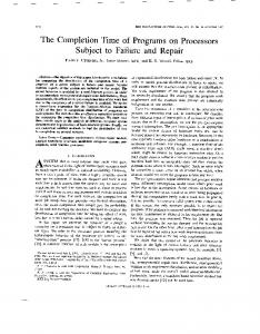
Figure 3. Real and CPU times for different pattern buffer sizes. We performed these simulations on the remote estimator with the wide area network environment, as described in Table 2.
local-host configuration is unexpectedly higher than the corresponding time over the LAN because the only machine used in the experiment (in the local-host case) was more heavily loaded when both the JavaCAD client and server ran on it. Figure 3 shows the buffer size’s effect on simulation speed. The experiment’s purpose was to estimate the RMI overhead caused by calling the remote power estimation method and by passing input pattern data between the client and server, so we disabled the actual call to the PPP simulator in the power estimator. Thus the runtime increase came only from RMI overhead, not power simulation. The plot clearly shows that a large pattern buffer is very helpful in amortizing RMI overhead. Both real execution time and CPU time decrease with increasing buffer size, despite diminishing returns with buffer sizes larger than 50% of the data size (communication setup overhead becomes small compared to the time required to send data). In conclusion, buffering is helpful but is not convenient for arbitrarily increasing buffer September–October 2002
size, because it leads to an increase in memory use with almost no speedup.
Virtual fault simulation The requirements of IP protection raise a barrier at the boundaries of each IP component: The IP user cannot pass the barrier to look at the component implementation, and the IP provider cannot look outside the component embedded in a design. Hence, the early estimation of any design metric before IP disclosure involves both users and providers. Providers must supply reliable estimators for their components; users must evaluate and compose the estimators associated with all components. If the estimators do not contain any IP, the providers can statically precharacterize them and distribute them with the component specification. If the estimators contain IP, JavaCAD provides a runtime communication protocol to let providers perform contextdependent dynamic estimates. Both cases treat typical cost metrics (area, delay, and power) as local, additive properties, which providers can
101
Design Reuse
independently evaluate for each component. Users can sum these to obtain global design metrics. Fault detection for a component in a larger design Unfortunately, fault detection is not a local, additive property. The detection of faults in a component embedded in a larger design entails ■ ■ ■ ■
signal propagation from the design’s primary inputs to the component’s inputs, fault activation within the component, fault propagation to the component’s outputs, and error propagation from the component’s outputs to certain primary outputs of the design.
The first and last steps involve the user’s IP, whereas the two middle steps involve the provider’s IP. Such intertwined involvement makes it difficult to precharacterize detectability metrics. Providers should supply complete information about each IP component’s detection properties—namely, the output pattern produced by the component corresponding to any possible input configuration or any possible component fault. This is a huge amount of information; worst-case extraction time and representation size grow exponentially with the number of inputs and linearly with the number of faults. On the other hand, users exploit only a small subset of such information during a typical fault-simulation experiment. Extension to virtual simulation mechanism These observations suggest that users and providers should exchange dynamic, rather than static, information at runtime to enable the fault simulation of IP-based designs. For this reason, we extended the virtual simulation mechanism (described earlier) to address the additional issues involved in fault simulation: ■
■
102
Local fault detection depends on global controllability and observability properties that providers cannot independently evaluate. A good test sequence is IP that might need protection.
We see virtual fault simulation as a twophase process. The first phase involves building a target fault list for the entire circuit: This fault list is a local, additive property that providers can precharacterize for each component and make available to users. To guarantee IP protection, symbolic names represent internal faults. The user builds the fault list for the entire design by composing the symbolic fault lists of all components. The second phase is fault simulation. For each user’s test pattern, this phase simulates the design’s fault-free behavior and makes available to the provider the signal configuration at the IP component’s inputs. The provider, in turn, returns the corresponding detection table. A detection table provides a partial representation of the component testability properties corresponding to a given input configuration. This table tells the user which output pattern the component would produce in response to the given input pattern, in the presence of each possible internal fault. Each row of the table associates an erroneous output pattern with the list of symbolic faults that would cause that error. Notice that a component’s detection table is nothing but a local, IP-sensitive parameter that a provider can independently evaluate for a given input pattern and return to the user. However, the user cannot directly sum detection tables to obtain global detection properties. Rather, these tables merely provide the user with the information required to perform fault injection and propagation for the current test pattern. To inject and simulate fault f of component M, the user injects, at M’s outputs, the output pattern associated with f in M’s detection table (if it exists) and propagates its effects to the design’s primary outputs by simulating the fault-free behavior of all other components. If an error occurs, the simulation detects fault f along with all other faults associated with the same output pattern, and the simulator can drop these faults from the fault list. Virtual fault simulation in JavaCAD For the sake of simplicity, we implicitly refer here to stuck-at faults in gate-level combinational circuits, but extensions to general fault models and sequential circuits are also feasiIEEE Design & Test of Computers
ble. We use static estimation to build the design’s fault list as the union of its components’ symbolic fault lists. We use dynamic estimation to perform fault simulation. JavaCAD represents detection tables as objects of the DetectionTable class, derived from the ParamValue class used to represent any parameter. For component M and a given input pattern, the detection table contains the list of all possible erroneous output configurations of M. It also contains the symbolic list of internal faults that can provoke each error. Figure 4 shows an example circuit (a half adder) that contains IP block IP1. The figure shows IP1 implementation (hidden to the user) within the dashed box. The stuck-at fault list for IP1 is {I1sa0, I1sa1, I2sa1, I3sa1, I3sa0, I4sa0, I5sa1, I5sa0, I6sa1}. To build this list, the provider exploits basic fault dominance, and the user directly handles faults affecting input or output signals. Suppose we want to evaluate whether input pattern ABCD = 1100 detects fault I3sa0. Propagating input values A and B gives E = 1; hence, the inputs of IP1 are 10. Figure 4b shows IP1’s detection table, corresponding to IIP1 = 1, IIP2 = 0. Looking up the detection table for the faulty output values associated with I3sa0, we obtain 00 (as opposed to the fault-free configuration, 10). Unfortunately, such a faulty value on OIP1 does not propagate to primary output O1, because D = 0; hence, pattern 1100 does not detect fault I3sa0. On the contrary, input pattern 1101 detects I3sa0, leading to the same detection table (because the input configuration for IP1 is the same), but the faulty value at OIP1 now propagates to O1. Pattern 1101 also detects fault I4sa1, because this fault causes the same error at the outputs of IP1. At the end of each simulation time instant, each module gets an estimation token, which the module’s detection table fits in. Current fault-free input signals go to the module estimator to construct the corresponding detection table. After collecting the detection tables for all design components, the dynamic-estimation controller uses them to determine the actual faults detected by the current test pattern, as Figure 5 shows. Detected faults drop from the fault list, and the simulation history annotates them to repreSeptember–October 2002
IP1 A
E IIP1
B C
D
I1 O1
I2
IIP2
I3
OIP1
F
I4 I5 O2 I6
(a)
Faulty output (OIP1, OIP2)
OIP2
Faulty list
11
{I6sa1}
00
{I3sa0, I4sa1}
(b) Figure 4. Example circuit (half adder) containing IP block IP1 (a), and IP1’s detection table for IIP1 = 1, IIP2 = 0 (b).
//Step 1 for each undetected fault f of module M in fault list FL find faulty output signal configuration s associated with f in detection table of M //Step 2 if s exists //Step 2a inject s in fault-free design and simulate its effects, retaining current signal values at design’s primary inputs; //Step 2b if primary output configuration is different from fault-free one detect each fault associated with s in detection table of M
Figure 5. Pseudocode showing how the dynamic estimation controller uses detection tables to determine faults detected by the current test pattern.
sent the incremental fault coverage obtained with the actual test sequence. To perform step 2a, we instantiated a new simulation controller with the following properties: ■ ■
■
It has only one simulation time instant. Primary inputs assume the signal values they have in the fault-free circuit at the current time. For this scheduler only, the simulation controller replaces faulty module M’s event-handling function with a function that assigns faulty signal configuration s to M’s outputs regardless of its input values.
103
Design Reuse
JavaCAD event scheduling and handling, which supports running multiple schedulers on concurrent threads, make this procedure possible. Hence, any event handling in modules depends on the actual scheduler dispatching the event, and does not affect what other schedulers perform. Thus, no reset or save/restore action among different scheduler runs is necessary.
JAVACAD SUPPORTS hierarchical design,
gate-level and RTL abstractions, remote IP (on the Internet), and parallel simulation. Future developments will address higher abstraction levels and flexible simulation setup with interactive client-server negotiation of simulation parameters. ■
References 1. R. Seepold and A. Kunzmann, eds., Reuse Techniques for VLSI Design, Kluwer Academic, Norwell, Mass., 1999. 2. M. Dalpasso, A. Bogliolo, and L. Benini, “Specification and Validation of Distributed IP-Based Designs with JavaCAD,” Proc. Design Automation and Test in Europe Conf. (DATE 99), IEEE CS Press, Los Alamitos, Calif., 1999, pp. 684-688. 3. M. Dalpasso, A. Bogliolo, and L. Benini, “Virtual
Alessandro Bogliolo is an assistant professor in the Department of Engineering at the University of Ferrara, Italy. His research interests include CAD of digital ICs and systems, with emphasis on low-power design, IP protection, and signal integrity. Bogliolo has a BS in electrical engineering and a PhD in electrical engineering and computer science, both from the University of Bologna, Italy.
Luca Benini is an assistant professor in the Department of Electronics and Computer Science at the University of Bologna, Italy. He also holds visiting researcher positions at Stanford University and Hewlett-Packard Laboratories in Palo Alto, California. His research interests include CAD design of digital circuits (with emphasis on low-power applications) and the design of portable systems. Benini has a BS in electrical engineering from the University of Bologna, Italy, and an MS and PhD in electrical engineering from Stanford University.
Simulation of Distributed IP-Based Designs,” Proc. Design Automation Conf. (DAC 99), ACM Press, New York, 1999, pp. 50-55. 4. S. Hauck and S. Knoll, “Data Security for WebBased CAD,” Proc. Design Automation Conf. (DAC
Direct questions and comments about this article to Marcello Dalpasso, DEI, Università di Padova, Via Gradenigo 6/A, 35131 Padova, Italy;
[email protected].
98), ACM Press, New York, 1998, pp. 788-793. 5. A. Bogliolo et al., “Power and Current Estimation
For further information on this or any other comput-
of Cell-Based CMOS Circuits,” IEEE Trans. Very
ing topic, visit our Digital Library at http://computer.
Large Scale Integration (VLSI) Systems, vol. 5,
org/publications/dlib.
no. 4, Dec. 1997, pp. 473-488.
Marcello Dalpasso is an assistant professor of computer science at the University of Padova, Italy. His research interests include fault modeling and simulation, and CAD frameworks and tools for IP protection in EDA. Dalpasso has a BS in electrical engineering and a PhD in computer science, both from the University of Bologna, Italy.
104
IEEE Design & Test of Computers