S
E
L
F
-
T
I
M
E
D
D
E
V
I
C
E
S
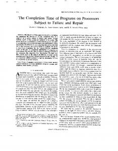
Designing Self=Timed Devices Using the Finite Automaton Model VICTOR I. VARSHAVSKY &YNCHRONOUS SYSTEMS of-
fer many advantages in terms of performance and power. Designing them, however, is essentially an art (see the Designers as artists box), and the quality of the final circuit implementation depends greatly on the designer’sskill. Our research, therefore, defines a procedure that reliably accomplishes the routine work associated with designing one class of asynchronous systems, self-timed devices. We do not intend to take the designer out of the design process; rather, our procedure frees a designer to review more possibilities. Our procedure synthesizesa selftimed device with external inputs from a finite Mealy automaton specification. We chose to use that specification and a two-register structure with master-slave flipflops for two reasons: Representing behavior specifications in finite automata language is widespread and supported by many CAD systems. It also has a good theoretical and practical basis. 14
One reason preventing wide use of the conventional asynchronous approach is the necessity of antiMARAKHOVSKY race coding, which causes major VADlM V. SMOLENSKY complications in an implementation. In this sense, self-timed realUniversity of A i m izations take the middle position between synchronous and asynThe authors suggest a procedure chronous ones. The inputs and outfor designing a self-timed device puts of self-timed circuits usually have a two-phase behavior (codedefined by the finite automaton spacercode, ...)’and a four-phase model. This procedure proves interface with the environment useful when designing these (requestcode-acknowledgementdevices using the available spacer-request, ...).These characsynchronous behavior teristics of the inputs and outputs, specifications. They illustrate the in fact, organize synchronous b e havior and therefore allow specifieffectiveness of their procedure by cation in synchronous finite applying it to the design of a stack automata language. However, the memory and constant problem of obtaining correct ciracknowledgement delay counter. cuit behavior (eliminating races, for example) stays outside the specification. Proper transitioning w As we will show, the Mealy au- of the specification to the realization tomaton’s self-timed realization structure guarantees gatedelay insenwith a two-register structure has a sitive behavior and provides the correct simple and evident solution. For circuit behavior. the given examples, it possesses a Such an approach is not a methodcomplexity close to that of the syn- ological novelty. This article illustrates chronous realizations. its particular application to a situation VYACHESIAV B.
0740-7475/95/$04.00 0 1995 IEEE
IRE€ DRSION & TEST OF COMPUTERS
that often arises when designing selftimed devices using the available synchronousprototypebehavior specification. For asummary of the research supporting this approach, see the Bac“kgroundbox (next page).
Specification problems We must first derive the device behavior specification.This process is informal and produces varying results. In addition, a specification of minimal complexity doesn’t guarantee minimal implementation complexity. Changing input specifications,however, achieves a more significant improvement in circuit solution quality than perfecting formal synthesis procedures. (Of course, thisdoesn’t mean that these procedures need not be perfected.) We chose to present input speeifications for formal methods as change diagrams that are extensions of signal graphs. Only a c m c t change diagram has a self-timed implementation. To achieve correctness, we might change the initial specification, for example, by inserting extra intermediate signals. Then we proceed from the correct change diagram to Muller’s diagram, a special state graph. From the set of states in this graph, we obtain truth tables for signal functions and derive Muller’s circuit. Reasonable insertion of intermediate signals into the initial specification often leadsto a significant simplificationof Muller’s circuit. Researchers have studied inserting such signals automatically, but we do not consider their algorithms satisfactory. To construct a change diagram specification of a device, we must at least know its input and output signals. For example, in the case of a control unit co ordinating the interaction between asynchronous, concurrent processes, we know beforehand the signals initiating processesand the Acknowledge signals. For this case we can rather easily derive a change diagram description of the autonomous system (consisting of the con-
Designers as artists Despite successes of theory and CAD developments, logic design is still an art and will apparentlyremain so for a long time. Many designersand researchers understandthis fact perfectly, as confirmed by the frequent appearanceof brilliant, new circuit solutions in various articles and patents. The authors of one
book state Different fypes of support are needed during each step or phase. For example, during formulation and generation, designers tend to be “artist,” while during evaluationand selection, designersare “analyst.”The artist versus analyst distinction has clear and important implicationsfor how the structure and flexibility of the support should vary across design phases.’ Designers usually display their skills in a fortuitous choice of a basic struc-
ture within which thy derive the device behavior specification, It is difficult, however, to optimize a specification, and vague optimization criteriaoften compound the difficulties, Unfortunately, no regular way exists to connect the initial structure (within which designers seek a solution) directly to the expectd result. Experienceshows that different devices are easier to design using certain structures. Currently, designers merely search among the various structures and specifications. Our god is to develop a design procedure that starts with Mealy’s finite-avtomaton specification.
trol unit and the controlled processes) functioning where these signals repre sent asynchronous processes. In such a system, inserting intermediatesignals to simplify realization of the control unit is the problem. More difficult specification problems ariseif 1) device input and output signals are not defined beforehand, and 2) a deterministicmodel cannot describe environmental behavior. In the first case, the designer can design a preliminary device structure as a basis for choosing signals necessary for the specification. The second case requires either inserting a vertex of free choice into the model and modernizing the formal method, or “unwinding” the specification (linearization).
Design procedure Our procedure, then, intends to obtain a correct change diagram specification from a finite automaton model. Although self-timed devices are asynchronous automata, we will not use asynchronous automaton models to d e fine them. This is because these modelssolve problems like antirace coding of internal states and hazard-free implementation of logic functions. A selftimed device’s main design problem is fixation of transient process completion moments in its circuit. The circuit certainly must be free of races and hazards, too, but fighting them is an attendant problem. Global methods handle races and hazards. They also often lead to better circuit solutions than that of special
S
E
L
F
-
T
I
M
E
D
D
E
V
I
C
E
S
Background A nonautonomous automaton must ir;teradwithanenvironmentw+lichforms admissible input sequences for it and senses its processing results. For a system comprising a finite automaton and its environment, three structural models reflect various approaches to timing organization: synchronous, asynchronous, and matched. We are interested in the matched model in which environment forms an automaton work step, and the automaton forms o step of the environment work. The matchedmodel uses a handshake method as its basic mechanism. In general, a request denotes change of the input state, and an acknowledgement denotes change of the outputstate. Since we use code for automaton inputs and outputs, it would be more correct to say "change of a class of input or output States."
We define a self-timed automaton as a matchedautomaton in which a change in an output-stateclass finishes the transition caused by a change in an inputstate class. This occurs irrespective of delays in the elements constructing the automaton. This definition i s not formal and emphasizes only that a self-timed automaton must correctly perform the automaton conversion under any ratio of delays of its dements. This requirement is feasible when using special coding systems and restrictions on the characteristic of delays in elements and wires. The following Muller's hypothesis of delay characteristics conforms well to practice: 1 ) delays can be both inertial and pure; 2) delays in elements and Dieces of wires from an element oubut Lp to a fork can be of any finite vahe;
methods developed within the theory of asynchronous automata. We use the classic finite Mealy au16
and 3)wires after a fork have a skew in delay values not more k n the minimum delay of an element. In general, designers use self-synchronized code systems to code the input, output, and internal states of on automaton. Our earlier work provedthe possibility of designing a self-timed implementation of an arbitrary finite automaton consisting of a combinational circuitand memory elements. We also developed methods to synthesize self-timed automata from electric-potentialelements. To do this, we use methods and p m dures designing self-timed realizations of Booleanfunction systems, m r y elements,and the circuits signalingtransition processes completion in those elements. To create formal methods of self-timed circuit synthesis, we need formal models. These models must reflect possible work concurrency and interactionasynchronism between different parts of the device. In this case, unfortunately, a finiteautomaton model representing a sequential machine is useless. Known formal methods of self-timed device synthesis use dynamic models for specifying parallel asynchronous processes in circuits. These models include Muller's diagrams,' signal graphs, and change diagrams.2 Synthesis methods based on such modelswork well for designing autonomous devices. When synthesizing devices with external inputs and outputs, the specification-simulating environment behavior must complement the general device behavior specification.This insertion usually requires "specification linearization,"2 a multiple unwinding of the general specification that significantly complicates both the
specification procedure and synthesis.
Also,some research derives the general specification ofthe "&ce-envimment" system using vertices of free choice3 rather than linearization.
ontheolherhad,thew$l-deveioped and widely used language of finite autwnato dlaws simple determinutionofthe required device-environment interaction behavior. The idea of joining the odvaniugesof cardullyd i e d finiie-autmaton models with methods of dktimed structure specification and synthesis, while desirable, is not original. We began investigating self-timed structures ex& frwn such models. Several studies using finite automaton models to design selftimed devices eXist.3A
References 1. D.E. Muller and W.S. Bartky, "ATheory of Asynchronous Circuits," Reports 75 and 78, Digital Computer Lab., University of Illinois, 1956, 1957. 2. M.A. Kishinevsky et al., Concurrent
Hardware: The Theory and Practice of Sell-Timed Design,J. Wiley and Sons, London, 1993. 3. T.A. Chu, "Synthesis of Hazard-Free Control Circuits from Asynchronous Finite State Machine Specifications," Proc. TAU-ACM Int'l Workshop on Timing Issues in the Specificationand Synthesisof Dgital Systems,Princeton University, Princeton, N.J.,1992,p. 28. 4. T.A. Chu, "An Efficient Critical RaceFree State Assignment Technique for Asynchronous Finite State Machines," Proc. 30th Design Automation C o d , Assn. of Computing Machinery, New York, 1993,pp. 2-5.
In this graph, S, and S, belong to the tomaton model for designing a self-timed device. The transition graph, shown in set of internal states;X,and yi belong to Figure 1, presents such an automaton. the sets of input and output characters. I l E E DESION C TEST OF COMPUTERS
The pair X J Y , marks each arc leading from one state to another. The automaton passes from state Si to state S,under the influence of input X,producing output 6. Let us consider only those automata in which each internal state is attainable from any other state, that is, those with connected transition graphs. This restriction is not excessive, because, first, connected automata are of the greatest interest. Second, any unconnected graph can always be converted to a connected one by using dummy input and output characters. Our procedure for designing a selftimed device consists of the following steps: 1. choice of a standard self-timed realization for a finite automaton 2. reduction of an automaton transition graph to a simple cycle graph 3. construction of a change diagram device specification 4. application of formal methods to the change diagram to obtain Muller’s circuit for output and memory element excitation signals
Standard automaton realization. Step 1 defines the automaton structural scheme; the rules governing its interaction with the environment;coding input, output, and internal-state characters; and the memory element structure. Only logic functions of the allotted signal stay undefined. Now we can define the partial order of signal change for the signal sets representing the automaton’s inputs and outputs as well as the memory element signals. However, the environment’snondeterministic behavior (it chooses the next input set in an unknown way) is a problem. Two studies’Jpropose canonical approaches that allow us to simplify the synthesis procedure. Using them, we obtain standard realization circuits. The memory element determines the type SPRING 1 9 9 5
of standard realization. Standard realizations use irredundant coding of automaton internal states, unlike asynchronousautomata,which use antirace coding. A standard realization contains a combinational circuit, parallel register, and perhaps, an indicator of transient process completion moments. D flip-flops with two-rail inputs or T flipflops form the register. In this article,we use a memory element of two masterslave RS flip-flops. Special design methods, as well as proper information coding, provide invariability of circuit behavior from element time parameters. Such code systems are selfsynchronized. For selfsynchronized codes, set B appearing at the output indicates the completion of a transition from set A to set B. Selfsynchronized codes are a universal and unique tool for fighting functional hazards. Asynchronous automata theory usually uses neighbor or quasi-neighbor coding methods. Such coding systems can be treated as single-phase selfsynchronized codes that are overly redundant. They allow direct transition from one character to another. Those self-synchronized codes where every working character alternates with an empty one (spacer) are more convenient.Note that using such sequences removes the restriction peculiar to asynchronous automata that no character can follow itself. A working input character initiates the active phase of the device work; the spacer initiates the passive phase. The selfsynchronized code of such sequences are twophase. The most commonly used twophase, selfsynchronized codes are equalweight codes and codes having an identifier (Berger’s codes). These are the basis of all other selfsynchronized code systems. We prefer equal-weight codes consisting of sets with a fixed number of ones. An example is two-rail code that represents each information bit by two
Figure 1. Mealy automaton transition graph. binary variables representing the active phase contrary values. Spacers are sets consisting either of all zeroes or all ones. Optimum equal-weight code (Spemer‘s code) has the least redundancy. Its sets of length m contain ml2 ones. In standard realizations, we usually use two-phase self-synchronized code systems for input and output states. That system defines the automatonenvironment interaction.The automaton replies to a working set with a working set and to a spacer with a spacer; the environment replies to a spacer with a working set and to a working set with a spacer. It is also important to choose rules governing the interaction between different parts of the automaton structural diagram. We discuss this problem later.
Reducing the automaton graph. In step 2, we unwind the automaton transition graph into a simple cycle to change free choice of the next input characterto a deterministic choice. The unwound graph defines a sequence of input characters that causes all the possible transitions in the automaton and is a loop that must pass every arc at least once. This guarantees the definition of all possible transitions. In such an unwinding, some statescan meet repeatedly. We can reduce a connected, oriented graph to a simple cycle in more than one way. We may wish to find its optimal unwinding; that is, the one containing a minimum number of vertices. The following is a possible algorithm for doing so: 1. compile the set of possible simple cycles from the automata graph 17
S
E
L
F
-
T
I
M
E
D
D
E
@=.a
tx, txp
(a)
_:;'.
txl + -i?+
>C t x q + -r3
(b)
-
tr,
--c ty,
A > C
t r 3-+
V
I
C
E
S
->-c >-c >--c ty,
-41
ty3
+-xl
>c -xp ty3 +
-x,
-Y2
-Y3
- >c -+ ts,
>
c
V
ts3
2,+-y2 -s3 +-y3
(e)
Figure 3. Possible transitions in the unwound automaton graph and heir representation by signal graphs: no state change (a),partial order of signal change [b), state change (c), successive subtransitions {ti), and a signal change order (e). Figure 2. Memory element based on two flip-flops.
2. find all possible subsets of this set that cover all the arcs of the graph 3. choose the subset with the minimum number of cycle vertices Any coverage of the graph is adequate for our purposes because all coverages define the same automaton;the optimal coverage simply reduces the subsequent work of the designer. A designer next reduces the automaton graph to a simple cycle graph by 1. removing any two cycles containing at least one common vertex from the coverage 2. breaking both cycles by disconnecting the arc between the chosen common vertex and the destination, then connecting the broken cycles to form a new cycle and returning it to the coverage 3. repeating this process until one cycle remains in the coverage This algorithm converges if the initial automaton graph is connected.
Constructing change diagram specifications. After unwinding the transition graph, we construct a linearized change diagram specification 18
of the device on the allotted signal set. The standard realization type determines the way we construct it. Two flipflops with heteropolar control represent every variable coding internal state of the automaton. Figure 2 shows a possible circuit of such a memory element. It contains four AND-NOR gates with output signalss,$and r,!. The same characters indicate both the gate outputs and signals. The gates form two simple RS (s,$)and i?x (r,!) flip-flops working as masterslave. A RS flip-flop changes its state through transit state (0,O) and a flipflop changesits state through (1,l). The signs * and " mark the inverted outputs of the flip-flops. Set signals S and R are the external inputs of both flipflops. Figure 2 shows the memory element initial state that corresponds to keeping the value of zero. The value one is written into a memory element in two phases. In the first phase, signal S = 1 switches the left flip-flop; in the second phase, when S = 0, information moves from the left flip flop to the right. Double change of signal R writes zero in the same way. To construct the standard realization of an automaton we must code input, output,and intemalstatecharacters. Let two-phase, equal-weight,selfsynchronizing codes represent input and output characters. This establishesthe rules of
interaction between the automaton and the environment. We use binary code to represent the internal states. After coding, we must define the rules of interaction between different parts of the automaton structural scheme. After that we can derive the change diagram specification. Let us accept the following rules: 1. Every transition executes in two phases. The first phase startswith a set of self-synchronizing code at the automaton input and finishes when a set of code appears at the output. The second phase starts with a spacer at the input and finisheswhen a spacer appears at the output. 2. If the transition does not cause a change of state, then the input signals are the immediate cause of output signal changes. Figure 3a shows such a transition. 3. We break an automaton transition from one state to another (Figure 3c) into two successive subtransitions. Figure 3d shows the subtransitions. Automaton states Siand S, correspond to statesMSi and Msj of its memory ele ment master flip-flop. MS,changes to M q through intermediate state Ssj rep WEE DESION I TEST OF COMPUWRS
resented by the memory element slave flipflop. A selfsynchronizing code set at the automaton input initiates the first transition phase and causes switching of the necessary number of slave flipflops. This leads to the appearance of a self-synchronizing code set at the output indicating phase completion. In the second phase, when the spacer appears at the input, the spacer writes the slave flipflop states into the master flipflops. After this, the spacer appears at the outputs of the automaton, indicating second phase completion. Let us code the input and output characterj of the automaton so that variablesx, andx, of setX,, andvariablesy, and y3of set V,have the value one, and the spacers include only zeroes. Then a transition like the one shown in Figure 3a corresponds to the partial order of signal change in Figure 3b. Assume the codes of states Siand Si differ in variables s, and s3and in state Si (s,= 0 and s, = 1). Then by coding charactersX, and F i n the same way we can easily represent the transition of Figure 3c by the signal change order in Figure 3e. Note that this graph has no flipflop excitement signals. During synthesis, we will build excitement functions into the flipflop gates. Such an approach allows the synthesis system to derive the necessary types of flip-flops (RS, D, or 13. We thus construct the signal change orders for every transition of the automaton graph unwound to asimple cycle. After defining the initial marking, we obtain the signal graph specification for the device. We emphasize that the specifications obtained from different unwindings of an automaton graph, when processed by the synthesis procedure, must lead to the same result. We can strictly prove this statement.
Self-timed stack memory As an example, we first applied our procedure to the design of a self-timed stack memory. Several approaches exSPRINO 1 9 9 s
st for designing this kind of memory; ye divide them into two basic classes: egister structures and memory-based ,tack. Studies of self-timed stack design isually consider register structures? We vi11 consider the second approach. In a usual CMOS static-memory array with two-rail representation of the data lath, sufficiently simple tools indicate ,cad-operation completion. The main lroblem is indicating write-operation :ompletion. We solved this problem4 y breaking the write process into two lhases: reading information and rewritng it. Memory detects rewrite compleion by checking whether the code ieing written coincides with the code n the data path of the read. The details If self-timed memory organization and jesigning the control circuits are out;ide this article’s scope. Figure 4 presents the stack structure. t contains a self-timed memory array, ;tack pointer, and control unit. Signals i and W initiate read and write operaions. They first enter the self-timed memory array and control unit to de.ermine the stack pointer work mode. 4ck is the signal that acknowledges op?ration completion to the environment. 4dr is the set of address signals coming io the memory array from the stack pointer. Adr initiates the memory work, while R and W choose the mode. C is the set of control signals coming to the stack pointer from the control unit. The signal graph in Figure 5 describes the rules governing stack block interactions. We indicate active and passive signal states by + and -. Extra signal 0 unites W and R making them indistinguishable. Our goal is to design the control unit. To d o this, we must consider the stack pointer circuit, which produces memory block addresses.
Stack pointer. The stack pointer logic circuit should be simple because its complexity grows linearly with increasing stack size. We achieve thissim-
1 1 Stack pointer
Adr
I
Self-timed Data bus memory arrav
m
i
tTclT
W R Ack
Figure 4. Stack structure.
rto -Ack-
tC-
tAdr
tAck
-Adr-
-C-
-OJ
Figure 5. Rules governing stack block interactions.
plicity by increasing the number of external control signals and, hence, complicating the control circuit. Figure 6, next page, shows such a stack pointer circuit. It is based on a multistable flip-flop with multiphase control. Such a flipflop can come to stable states with violations of strict alternation of low and high levels at the gate outputs. For example, in the sequence, ..., 010100101 ..., neighborstate pair00 is a pointer. Compulsorily drawing the left gate of the pair 00 into state 1 (00- 10) shifts the pointer to the left. To shift the pointer to the right, we draw the right gate of the pair 00 into the state 1 (00-01). Thus, there are two control signals necessary for shift control, for example, D and U. However, if we change any of these signals once, the pointer will move to one of the sides without stopping. To prevent a through shift of the pointer, we double the number of the control signals and divide them into even (De,U,) and odd (Dn, UJ,as in the circuit of Figure 6. The circuit keeps the pointer when all the control signals equal 1. If the pointer is on an even position (corresponding to the two middle gates of the circuit) then De = 0 shifts 19
S
E
L
F
-
T
I
M
E
D
D
E
V
I
C
E
S
Using this description, we can easily represent the control unit by a Mealy automaton with the transition graph of Figure 7. The automaton states correspond to the following situations: WE-occurrence of a write by an even address WO-occurrence of a write by an odd address RE-occurrence of a read by an even address RO-occurrence of a read by an odd address
fjgure 6. Stack pointer.
w/u,
in particular, the interaction between the stack and the environment. Stack pointer behavior determines stack behavior. We represent it as follows:
If a write operation precedesa write,
U,=0 shiftsthe pointer one position
Figure 7. Control unit automaton graph.
it to the left odd position and U, = 0 to the right. The odd pointer positions in Figure 6 correspond to the two left and the two right gates. From these positions, D,=Oshifts the pointer to the left, and U, = 0 shifts it to the right. The pointer position corresponds to the memory array address line. Signal A, = 1 chooses the ith address line. The stack pointer determines values of A, according to the pointer position and control signal values.
Control unit. This unit produces the stack pointer control signals using input signals Wand R. The definition of this automaton behavior should describe, 20
up from an even position. U, = 0 shifts it one position up from an odd position. After this, the stack pointer produces the address signal. If a write operation precedes a read, pointer position does not change, and U, = 0 or Do = 0 produces the address for an even position; U, = 0 or De = 0 for an odd position. If a read operation precedes a read, De = 0 shifts the pointer one position down from an even position. Do = 0 shifts it one position down from an odd position. The stack pointer then produces the address signal. If a read operation precedes a write, the pointer’s position does not change, and U, = 0 or Do = 0 produces the address for an even position;U, = 0 or De = 0 for an odd position. U, = U, = D, = Do = 1 will reset the address signal.
To code four states, coding variables S, and S, suffice. Let variables, take values from set (e,o}and variable S, take values from set {r,w}.Then, clearly, the coding of the automaton states is neighbor since only one variable value changes in every transition. Such coding simplifies the automaton realization. We set the output signals, shown at the arcs of the graph in Figure 7, so that every variable that codes internal states breaks its set into two nonoverlapping subsets. Choosing such output signals must simplify its logic functions. For synchronousautomaton realization, the universal antirace method uses a two-register memory that divides the registers’ work in time. We find a similar approach useful for self-timed realization. For example, a pattern of self-synchronizingcode appearing at the inputs triggers a write to the first register. A spacer at the input causes information to move from the first register to the second. In some cases, the second register can contain a smaller number of simple flip-flops than the first. When the information moves, it must be compressed. We use this case in our example. Let variable S, correspond to RS flipflop Ye,Yoand variable S, to RS flipflop Y,. These two flip-flops form the first register. Since in every transition only one of these flip-flops changes its state,
c,
IEEE DESION & TEST Of COMWTeRS
-
- -L -- --J L ---
w tw -y1 + ty2 4 -U, -w +tz, the second register can consist of one flip-flop. Let it be flip-flop (Z,, 2,). -z2 +De+ -zl + tz2 + -R + -De-y4-y3+ tR Such automaton memory organizatyl -Do +-R +tzl + -z2 ++Do t R + -y2 tion, together with coding input and output characters using two-phase selftu,+ -zl tz2 -w -U,ty3 -y4 tw synchronizing codes, provides rnonot+Do-R +tz, 4 -z2 L t R -y3 + ty4 +-Do onic representations for all signal logic functions. In our case, the inputs and +De+ -Z1 + t Z 2 + -R + -DetY2-YI+ +R* outputs are already coded, and we can tw -y4 4 +ys 4 -U, -w +tz, -z2 ++U, easily check that these codes are twophase and self-timed.We have thus de- +U,-21 tz2 -w -Uoty1-y2+w+ signed the standard realization of the automaton defined by the transition Figure 8. Control automaton signal graph. graph of Figure 7. This graph reduces to a simple cycle graph rather easily. Two simple cycles, obtained by passing all the graph vertices clockwise and counterclockwise, Ai A, cover all the graph arcs. We construct an unwinding of the graph from these Figure 9. Modulo-2” counter stage. two cycles. We derive the linearized specification, represented by the signal graph in An arrangement of counter stages Figure 8, by unwinding the graph of the in a pipeline guaranteeing that the (b) automaton standard realization. Using response time is independent of this specification and formal synthesis Figure 10. Transition graph of the the number of stages methods, we obtain the following A counter contains two intercon- modulo-T counter stuge (a)and unwindMuller’s circuit: nected asynchronous pipelines. ing of the graph (6j. Counting signals propagate in one; Ye = Yo v wz, v Rz, carry and overflow signals propaY, = Y, v w gate in the other, but move in o p Free inputs of the most significant stage Yo = Ye v WZ, v RZ, meet the following boundary condiposite directions. Y, = Y, v R tions: input Pi connects to output A, and Z, = Z,R v Z,W v Z2UeD, Let us constructsuch a counter using constant zero feeds input QP A finite automaton with the graph these principles and our automaton apZ, = Z,R v Z,W v Z,D,U, proach. In a modulo-2”counter,n is the shown in Figure 10a represents a De = YoZ,Y, U, = Y,Z,Y, number of stages. Let the ith counter counter stage. The automaton has inU. = Y,Z,Y, Do = YeZ2Y, stage be the black box shown in Figure ternal states Soand SIthat correspond 9. It receives counting signals from the to keeping the information bit values 0 Considering these derivations as logic (i-1)th stage at input Ai and replies to and 1. Signal Ai= 1, which is the analog functions of AND-NOR gates, we can them at output Q, if there is no over- of clock signal for the automaton, initidraw the logic circuit of the control flow, or at output Po if overflow occurs. ates every transition. Therefore, this sigThe ith stage passes the counting signals nal does not appear in the transition automaton. to the (i+l)th stage through output A,; graph. The automaton passes from state Acknowledge signals respond to these Soto state S, on any condition; on the Modulo-2” counter with a signals at inputs Qi or Pi, depending on corresponding transition arc the conconstant response time Our second application example has the presence of overflow. The modulo- dition is marked 1 and the output sigmany ~olutions.~.’ Each solution uses 2“counter consists of n such stagescon- nals are Q, = 1 and A, = 1. The two basic elements of structural nected in series. The least significant automaton allows the transition from& stage interacts with the environment. to Soonly when it receives input signal scheme realization:
1-
1-
~
~
SPRINO 1995
21
S
E
+A, + -Yo
L
F
+tY1-
4,-
\
.t
-
+A,
T
-A, ++Si --t
I
M
4-
+-So+
E
D
D
+A, + -Y1 ++Yo
,i-*i0
+Q,
/ 1 -A, 1 1 -Q, +so
-A,
t
‘s“
(i1l
I!-
-? /;””
+p, e - - - -
t
+Yo+
-Yl+
+A, +-Q,+
-So+
+Si + -A,-
-
tQ,+
E
V
I
C
E
S
tomaton realization. Let us unwind the automaton graph to a simple cycle (Figure lob). Using this unwinding and the accepted standard automaton realization,we derive the signal graph specification,shown in Figure 11. From this specification,formal methods produce the following Muller‘s circuit:
-Q,
tY1
-Yo+
1
tA,
Figure 1 1. Signal graph specification of the counter stage.
Qi
.
t
-
Note that in this circuit the functions of signals Q,, Po, and A, are selfdepending, that is, they must be implemented as flip-flops madefrom a gate and an inverter. Signals Q, and E in function A, come from the gate outputs of the corresponding flip-flops. We can improve this solution by inserting changes into the signal graph specification. For example, the modified specification derived by removing two arrows, shown as dashed lines in Figure 11, provides simpler functions for Yl and A, Y, = Yo v Aisl A, =Po v YoSov YoQo
Pi
Figure 12. logic circuit of the counter stage.
1 or Pi= 1.Two arcsdepict this tran- 00 and a master flip-flop (So,S,) with sition since different output signals can transit state 11. The inputs and the outbe produced during it: Qo= 1 when Qi= puts of the automaton are already coded. We can easily check that for all 1, and Po= 1 when Pi= 1. One coding variable S suffices to transitions coming from any internal code two internal states. Let two simple state the codes of the inputs and outflip-flops correspond to it. They are a puts are self-timedand twephase. Thus, slave flip-flop (Yo, Y,) with transit state we have constructed a standard au-
Qi=
22
Other signal functions do not change. In this way, we can easily draw the counter stage logic circuit (Figure 12) from the Muller‘s circuit. We analyzed the performance of the counter circuit, measuring response time by the number of gates switched. That number equaled four for every change of the counting signal and did not depend on the number of stages. Our solution, then, does not exceed those already known in c~mplexity.~-’ IEEE DESIGN & TEST OF COMPUTERS
k K E ANY DESIGN PROCEDURE, Ours contains both formal and informal steps. Choosing the specification language, behavior specification, and basic structure is informal. Designers use theirexperience to make these choices. These choices, in turn, determine the quality of the solution. Transitioning the specification within a basic structure to a change diagram is a formal step. It allows us to obtain an self-timed implementation using wellknown formal methods? The facilities used for formal synthesis determines o lution quality. It is important to introduce the behavior of the basicstructure gates into the change diagram. Starting our design procedure at the gate level increases the quality of the solution.This article's limited length does not allow us to describe the details of this process. @
7. K. van Berkel, "VU1Programmingof a
Modulo-N Counter with Constant Response Time and Constant Power," Asynchronous Design Methodologies, IFIP, Vol. A-28, S. Furber and M. Ed-
wards, eds., Elsevier Science Publishers, New York, 1993,pp. 1-11.
Vadim Smolensky works at the University of Aim as a research associate, where he participates in the Self-Timing and EventDriven Systems research project. Smolensky received the DEng in computer science from Leningrad Electrical Engineering Institute.
Victor I. Varshavsky is a professor and head of the Computer Logic Design Laboratory at the University of Aim, Japan. His research interests are in the area of operation research,automata theory,logic design, and computer engineering.Varshavsky r e ceived the DEng degree in precise meReferences chanics from the Leningrad Institute of 1. A. Astanovsky et al., Aperiodical Au- Precise Mechanics and Optics. He also tomata, V. Varshavsky, ed., Nauka, holds a PhD degree from the Leningrad Institute of Aviation Instrumentation and a Moscow, 1976 (in Russian). 2. V.I. Varshavsky et al.,Self-TimedControl DrEng from the Institute of Control Probof Concurrent procesSes,V. Varshavsky, lems,Russian Academy of Science;both d e ed., Kluwer Academic Publisher, grees are in engineeringcybernetics. Boston, 1990. (Russian, 1986). 3. M.B. Josephs and J.T. Udding, "TheDesign of a Delay-InsensitiveStack,"in De-
Address questions or comments about this article to Victor I. Varshavsky, University of Aizu, Tsuruga,Ikki-machi,Aizu-Wakamatsu City, Fukushima, 956 Japan;
[email protected].
I k c t r o n i c Accou to Abstracts Woeks Beform Publication Access the IEEE Computer Society On-line Service via World Wide Web (http://www.computer.o@ or gopher (jnfo.computer.org)
signing Correct Circuits, Workshops in Computing, G . Jones and S. Sheeran,
eds., Springer-Verlag,New York, 1990, pp. 132-152. 4. V.I. Varshavskyet al., "MemoryDevice from MOS Transistors," USSR patent, CertificateNo. 1365129,IC1 G 1IC11/40, The Inuentions Bulletin, No. 1, 1988. 5. J.C. Ebergen and M.G. Peeters, "Modulo-N Counters:Design and Analysis of Delay-InsensitiveCircuits," Proc. Second Workshopon DBsigning Correct Circuirs, North Holland, Amsterdam, 1992, pp. 2746. 6. C.D. Nielsen, "PerformanceAspects of Delay-Insensitive Design," PhD thesis, Technical U. of Denmark,Lingby, Denmark, 1994. 8PUN6 1995
Vyacheslav B. Marakhovsky is also a professor at the University of Aim and is in charge of the Computer Networks Laboratory. His research interests include automata theory, logic design, and computer engineering. Marakhovskyholds the DEng in electricalengineering from the Leningrad Polytechnical Institute,a PhD in engineering cyberneticsfrom the Central Institute of Economics and Mathematics,RussianAcademy of Science,and DrEng in computer science from Leningrad Electrotechnical University. He is a member of the IEEE.
m
AbshactsandtablesofcontentsoflEEE &sign & Tesf of Compufetxand other ComputerSociety publications Conference calendar Career opportunities General membershipandsubscription information Calls for papers IEEE CornputerSociety PressCatalog Volunteer and staff directory
23