Development of a Spherical Induction Motor With Two ... - IEEE Xplore
Recommend Documents
Direct Torque Control of Induction Motor With Fuzzy Stator. Resistance Adaptation. F. Zidani, D. Diallo, Member, IEEE, M. E. H. Benbouzid, Senior Member, IEEE ...
based Direct Power Control with Space Vector Modulator. (DPC-SVM) is applied to control of the PWM rectifier. The inverter with induction motor is controlled via ...
Abstractâ In this paper, a new high performance induction motor drive is presented. The induction motor is controlled with four proportional plus fuzzy PI ...
state, a new control scheme with skin-effect estimation to improve the transient accuracy, and overcurrent protection to be able to control the stator currents while ...
Abstract - Although many techniques for high performance torque and flux control in three-phase induction motors are already available, most of them were not ...
were used for study. Keywords: Condition monitoring, rotor fault diagnosis, motor current signature analysis, air-gap torque spectrum, air-gap torque estimation.
Liverpool John Moores University, Liverpool, U.K.. Abstract: An induction motor is the most frequently used electric machine in high-performance drive ...
Abstractâ This paper proposes a self-scheduled control method for the induction motor. We design a controller with two degree of freedom for the induction ...
15 Phase Induction Motor Drive With 1:3:5. Speed Ratios Using Pole Phase Modulation. Umesh B S, Sivakumar K. Department of Electrical Engineering.
AbstractâSensorless drive control has been widely studied in recent years due to the numerous advantages regarding potential failures of position sensors, ...
Multilayer Control of an Induction Motor Drive: A Strategic Step for Automotive Applications. Hainan Wang, Steve Pekarek, Member, IEEE, and Babak Fahimi, ...
This paper deals with the dynamic characteristics of a linear induction motor (LIM) in terms of acceleration times and jerk condi- tions. We employed Matlab ...
AbstractâThis paper presents a novel variable-frequency motor drive system for a three-phase induction machine. In this drive system, the machine is excited by ...
A Novel CSI-Fed Induction Motor Drive. Abdul Rahiman Beig, Member, IEEE, and V. T. Ranganathan, Senior Member, IEEE. AbstractâCurrent source inverter ...
A Linear Induction Motor Control System for. Magnetically Levitated Carrier System. Abstract-A new electromagnetic suspension system has been devel- oped ...
Abstract -- The improvements of the new structure of a brushless DC (BLDC) motor with the low cogging torque for the ceiling fan is presented. The new type ...
Nov 1, 2014 - bottleneck for digital subscriber lines (DSL) technology. Dynamic spectrum ... IN a communications system where multiple users have competing utilities, the ... power throughout frequency such that the weighted rate sum. (WRS) of the ..
Estimation of Rotor Resistance of an Induction. Motor Using Extended Kalman Filter and Spiral. Vector Theory. Mohamed Menaa, Omar Touhami and Rachid ...
This paper presents the development of a cosimulation platform of induction motor direct torque control (DTC) drive. This paper provides advanced modeling ...
efficiency field evaluation faces a different environment from that for which IEEE Standard 112 is chiefly written. A field evaluation method consists of one or ...
Universidad Autonoma de San Luis Potosi. Manuel Nava No. 8, Zona Universitaria. 78290 San Luis Potosi, S.L.P. MCxico. rubenj aramil [email protected], { ralvarez, ...
response and robust control in ac adjustable-speed drives. How- ever, in the steady-state ... modulation is proposed for induction motor sensorless drives. The.
Abstractâ In this paper induction motor model has been developed in three phase frame of reference. A qualitative and analytical approach has been adopted ...
Speed Estimation of Induction Motor Using Artificial Neural Networks. Prashant Mehrotra, John E. Quaicoe and R. Venkatesan. Faculty of Engineering and ...
Development of a Spherical Induction Motor With Two ... - IEEE Xplore
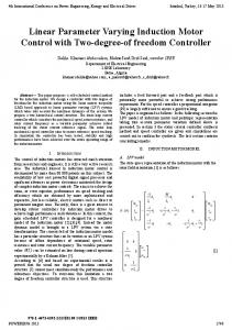
conversion principle is that of an induction motor. The paper first ... Index TermsâDesign, induction motor, modeling, multi degrees of freedom, spherical motor.
IEEE TRANSACTIONS ON MAGNETICS, VOL. 42, NO. 8, AUGUST 2006
2077
Development of a Spherical Induction Motor With Two Degrees of Freedom B. Dehez1 , G. Galary1 , D. Grenier2 , and B. Raucent1 Center for Research in Mechatronics, Université Catholique de Louvain, B-1348, Louvain-la-Neuve, Belgium SATIE laboratory, Ecole Normale Supérieure de Cachan, Avenue Robert Schuman, Campus de Ker Lann, 35170 Bruz, France This paper reports on the development of a spherical actuator with two actuated degrees of freedom (DOFs). The electromechanical conversion principle is that of an induction motor. The paper first discusses possibilities of adapting the actuator to a spherical rotor actuated with an unlimited angular range along two DOFs. These concepts are then characterized and compared by analytical and numerical modeling, and the final shape of the actuator, composed of a two-layer rotor with teeth surrounded by five inductors, is described. A prototype has been built, and its performance, in terms of characteristic torque-speed and efficiency, has been measured. Index Terms—Design, induction motor, modeling, multi degrees of freedom, spherical motor.
NOMENCLATURE
I. INTRODUCTION
Values
tp
Efficiency (-). Slip (-). Pulsation (rad/s). Power (W). Magnetic field strength (A/m). Magnetic flux density (T). Magnetic vector potential (Wb/m). Magnetic permeability (V s/A). Electric conductivity (S m/m ). Torque (Nm). Turn (-). Current (A). Surface current (A/m). Pole pairs (-). Electromechanical conversion parameter (N m s/rad). Displacement speed (m/s). Radius (m). Air gap thickness (m). External layer thickness (m). Surface (m ). Resistance . Inductance (H). Leakage inductance (H). Tooth proportion (%).
Digital Object Identifier 10.1109/TMAG.2006.876473
A
DVANCES in robotics and flexible production systems have motivated the development of new and unusual electrical actuators. However, most of these have only one actuated degree of freedom, whether linear or rotating, whereas many applications, such as robot wrists [1] or omnidirectional vehicles [2], require more. A classical solution then consists in combining several of these actuators using a mechanical transmission such as a parallel linkage [1] or universal wheels [2]. Generally complex and heavy, they therefore reduce the dynamical performances and complicate the control of the device into which they are integrated. The idea of a multi-DOF actuator, and in particular a two-DOF spherical actuator, is based on the presumption that such a construction should ensure a higher level of precision, better dynamic performance, and lower friction than two-DOF structures using several independent one-DOF actuators. A number of actuators able to generate multi-DOF have been developed in recent years. Kant carried out a review [3] of various actuators combining rotating or linear motions to achieve two and three actuated degrees of freedom. Wang et al. proposed a synchronous actuator with a permanent magnet spherical rotor and a stator consisting of three orthogonal windings [4]. Roth and Lee developed a three-DOF spherical actuator operating on the principle of variable reluctance [5]. In [6], Lee and Kwan presented a spherical stepper motor capable of three-DOF motion in a single joint. Davey et al. proposed an asynchronous motor consisting of a homogeneous spherical rotor surrounded by three sets of windings allowing rotations around three perpendicular axes [7]. Lastly, the ultrasonic spherical motor developed by Takemura and Maeno [8] can generate a three-DOF motion of a spherical rotor with a bar-shaped stator. In addition to the type of motion, linear or rotary, the number of actuated DOFs, and the principle of actuation, all these actuators are also characterized by the transmission principle and the range of the motion they generate. The actuator presented in this paper is composed of a spherical rotor actuated in rotation by induction along two DOFs with an unlimited angular range (Fig. 1). This last original characteristic is particularly constraining because it prevents applying a
IEEE TRANSACTIONS ON MAGNETICS, VOL. 42, NO. 8, AUGUST 2006
Fig. 3. Winding distribution around the spherical rotor for one-DOF rotating magnetic field. Fig. 1.
Principle of the two-DOF spherical actuator.
A. Stator
Fig. 2. Two-DOF spherical actuators used as element of a crossroad module between unidirectional conveyors.
“simple” degeneration of a traditional cylindrical motor. Moreover, it requires a transmission of the motion by direct friction between the load and the rotor. This friction drive, and the unlimited clearance it allows, as well as the number of actuated DOFs open up a broad spectrum of applications. Let us mention, for example, the use of three spherical actuators to obtain omnimobile robot platforms [9], [10] or, simply by reversing the omnimobile platform concept, crossroads for industrial conveyors (Fig. 2). Respecting the classical structure of a design process, this paper starts by describing the various possibilities of adapting the induction principle to the case of a spherical geometry actuated in rotation along two DOFs. It then presents the results of an electromagnetic characterization that highlighted the most interesting concepts. On this basis, a complete solution, integrating stator, rotor, and bearing, is proposed. A first prototype and the test bench allowing its operation, as well as the experimental results obtained thanks to this bench, are also presented. An analysis of the prototype performances and an overall discussion on the study conclude the paper.
II. CONCEPT DESCRIPTION From an electromagnetic point of view, any actuator is composed of stator and rotor elements. As regards to the adaptation of the induction principle to a spherical geometry, they can be considered separately.
The function of the stator inductors is to generate a slipping magnetic field along the rotor. For classical motors with a cylindrical rotor shape, the slipping magnetic field is rotating around the rotor axis. For a spherical rotor shape, there are two possibilities depending on whether the inductors generate a rotating field with one DOF, as for classical cylindrical rotors, or two DOFs. In the first case, an inductor, alone, will be able to generate a torque, and consequently, a rotation along a single fixed axis. To obtain a second actuated degree of freedom, it will thus be necessary to combine at least two of these one-DOF inductors (cf. infra). In the second case, the inductor, alone, is able to directly generate a torque, and thus, a rotation along any axis which is a linear combination of two perpendicular axes. Only one of these two-DOF inductors is thus needed to obtain two actuated DOFs. It should be noted that the shape of the stator structures proposed hereafter are similar to those introduced by Kaminski [11]. 1) One-DOF Inductor: One-DOF inductors are obtained by a simple transposition of conventional induction motors to a spherical geometry as shown in Fig. 3. Three windings, carrying sinusoidal current phases shifted by 120 , generate a rotating magnetic field around a fixed rotation axis. The path followed by the windings is quite significant because it influences the actuation effectiveness. Meridian shape windings are the only ones that generate, at any point of the air gap, a rotating magnetic field, and consequently a torque aligned with the rotating axis. As for parallel shape windings, they generate a magnetic field rotating around an axis which depends on the position in the air gap. Only a fraction of the generated electromagnetic torque therefore effectively contributes to the resulting effort, the balance being needed to counteract an antagonistic torque generated elsewhere. From a practical point of view, this configuration is not satisfactory mainly because it prevents access to the rotor to transmit the motion to the load. A solution consists in concentrating the windings near to a meridian, in order to release rotor access zones, and reduce those in the equator area, where they produce maximal torque. It also avoids winding concentration near the poles (Fig. 3).
DEHEZ et al.: DEVELOPMENT OF A SPHERICAL INDUCTION MOTOR WITH TWO DEGREES OF FREEDOM
Fig. 6.
Magnetic circuit for the two-DOF inductor.
Fig. 7.
Laminated magnetic core for the two-DOF inductor.
2079
Fig. 4. Magnetic circuits for the one-DOF inductor.
Fig. 5. Winding distribution around the spherical rotor for two-DOF rotating magnetic field.
In order to maximize the magnetic flux crossing the air gap, windings can be inserted in a magnetic circuit (Fig. 4). The latter can be materialized in various ways. If the purpose is to minimize the eddy current losses, the best solution is to use electrical sheets [Fig. 4(b)]. In this case, the sheets must have a variable thickness so that they are all parallel to the magnetic field lines. Moreover, they must all have different profiles so that slots, and thus windings, follow meridians and not parallels. If the purpose is to simplify manufacturing, another solution consists in machining the magnetic circuit from a solid material [Fig. 4(a) and (c)]. In this case, the choice of material is critical to avoid too significant degradation of the actuator performances due to high level of iron losses. To further simplify manufacturing, the slot apertures can be made straight [Fig. 4(c)], but once again to the detriment of the actuator’s performances. Finally, it is possible to manufacture the magnetic circuit from pressed powders [12], [13]. These consist of fine magnetic particles (e.g., 99% pure iron) insulated from each other by an insulating material (e.g., oxide coating for iron particles). This insulator makes it possible to reach high electrical resistivity in any direction and thus to limit induced currents. Considering the cost related to the development of the tools required in powder working, their use can be justified only for high volume production. The windings inserted in the magnetic circuit can be produced in a traditional way, starting from copper wire wound on a gauge before being inserted in the slots of the magnetic circuit. They can also be pressed between a punch and a die [14], or directly
into the slots of the magnetic circuit, in order to increase the filling factor, and consequently, the power-to-weight ratio of the actuator. 2) Two-DOF Inductor: Two-DOF inductors are obtained by superimposing two sets of three-phase windings such as those proposed for the one-DOF inductor. Placed at 90 to each other, as illustrated in Fig. 5, and with independent supplies, they allow to directly generate a rotating magnetic field, and thus a torque, with two DOFs. In the same way as for one-DOF inductors, windings must be placed in a ferromagnetic structure, such as that illustrated in Fig. 6, in order to facilitate the circulation of magnetic fields through the air gap. In order to limit the eddy currents and the associated losses, it is possible to make the magnetic circuit from electrical sheets (Fig. 7). However, since the magnetic fields generated by the two sets of windings define perpendicular planes, it is necessary to modify the shape of the magnetic circuit to prevent the 90 crossing of these magnetic fields. In order to fulfill that objective, a solution consists in creating longitudinal openings in the external yoke of the magnetic circuit. These openings prevent the magnetic field generated by the windings inserted in the external slots from circulating through this part of the magnetic circuit and thus crossing the magnetic fields generated by the other sets of windings. This ensures that the magnetic field is parallel to the electrical sheets throughout. For the windings, possibilities are similar to those advanced for the one-DOF inductors. B. Rotor Any spherical part containing electrical conducting elements could be used as a rotor. Nevertheless, some structures afford much better performances. Three structures producing increasing levels of performances but with corresponding levels of manufacturing difficulties are presented here.
2080
Fig. 8.
IEEE TRANSACTIONS ON MAGNETICS, VOL. 42, NO. 8, AUGUST 2006
(a) One-layer, (b) two-layer, and (c) two-layer-with-teeth rotors.
1) One-Layer Rotor: The first structure consists of a single layer [Fig. 8(a)] made from a material having both good magnetic permeability and good electric conductivity in order to simultaneously support the circulation of the magnetic fields and induced currents. In spite of its manufacturing simplicity, the performances of this kind of rotor are greatly reduced by the strong skin effect in ferromagnetic and conducting materials. 2) Two-Layer Rotor: The second structure consists of two layers [Fig. 8(b)]. The internal layer is intended only for the circulation of the magnetic fields and made from a material having good magnetic permeability and high electrical resistivity. The external layer is intended only for the flow of the induced currents and made from a material having good electrical conductivity but low magnetic permeability. Separation of ferromagnetic and conducting materials allows, at the price of a greater manufacturing complexity, to reduce the skin effect and thus to attain better performances. These are however still limited by the actual air gap that is increased by the thickness of the external layer. 3) Two-Layer-With-Teeth Rotor: The third structure is similar to the second except that the external conducting layer is crossed by a multitude of ferromagnetic teeth [Fig. 8(c)]. While preserving the advantages of the preceding structure, this last modification allows to increase the actuator performances by reducing the equivalent air gap of the external layer. In order to further increase these performances, the teeth could present a widening near the air gap, a spherical equivalent of the reduced slot aperture. Several possibilities exist to limit the eddy-current losses within the ferromagnetic parts of the rotor. The internal rotor layer can be made from electrically insulated magnetic powders [12] and [13]. As for the teeth, they can be made either from magnetic powders or from rolled up sheets. III. CHARACTERIZATION OF THE CONCEPTS AND COMPARISON Each concept suggested above can reach various levels of performances. To compare these, the main solutions were characterized on the basis of a parameter representing the electromechanical conversion efficiency of the actuator. The latter has the advantage of being easily evaluated from analytical or numerical electromagnetic models. A. Electromechanical Conversion Parameter is defined The electromechanical conversion efficiency by the ratio between the outgoing mechanical power and the
Fig. 9. Actuator and load torque-speed characteristic.
power transferred from the stator to the rotor. Its value depends directly on the actuator working point through (1) where is the slip between the rotor speed and the synchronous speed. Considering the definition of the slip, this first relation can be rewritten as (2) is the supply pulsation, is the rotor speed, and where is the equivalent number of pole pairs along the complete rotor circumference. It then appears that the closer the rotor speed is to synchronous speed, the higher the electromechanical conversion efficiency. However, the rotor speed depends not only on the load but also on the actuator characteristic, and in particular on its shape around the synchronous speed (Fig. 9). In this zone, the torque-speed characteristic is quasi-linear and can generally be replaced by a straight line. The higher the slope of this line, the higher the conversion efficiency. As a first approximation, it seems therefore possible to compare the conversion efficiency of two different actuators on the basis of the torque-speed characteristic slope around the synchronous speed. The latter slope can be approximated by the following ratio: (3) is the maximum actuator torque and is the where corresponding rotor speed (Fig. 9). Using the rotor current fre, which is proportional to the differquency ence between the synchronous and rotor speeds, we can replace expression (3) by the ratio (4) is the rotor frequency at maximum torque and is where the electromechanical conversion parameter used in this study to compare actuator efficiencies.
DEHEZ et al.: DEVELOPMENT OF A SPHERICAL INDUCTION MOTOR WITH TWO DEGREES OF FREEDOM
2081
B. Analytical Modeling The first part of the electromagnetic characterization is based on an analytical model introduced previously [15]. The latter gives the torque generated on one and two-layer rotors by one-DOF inductors according to parameters such as the supply frequency, rotor conductivity, air gap thickness, inductor size, and rotor speed. Based on Maxwell’s equations, some restricting assumptions were needed to find an analytical solution: • electromagnetic couplings between inductors are negligible; • electromagnetic phenomena are concentrated in the air gap and on the rotor surface; • boundary effects are negligible; • currents in inductors are degenerated to surface currents flowing at the interface between the stator and the air gap; • the stator material has infinite permeability; • all materials are linear and homogeneous; • sinusoidal steady state. These hypotheses, along with other more classical ones for electromagnetic devices, allow us to reduce the four Maxwell equations to just one, the magnetic diffusion equation:
Fig. 10.
Multilayer structure of the actuator for a two-layer rotor.
Fig. 11.
Influence of the rotor magnetic permeability.
(5) involving the magnetic vector potential , magnetic permeand displacement speed ability , electrical conductivity of the material . In addition to this simplification, the initial three-dimensional (3-D) spherical problem can also be reduced to a two-dimensional (2-D) plane problem composed of several layers, three for the one-layer rotors, and four for the two-layer rotors (Fig. 10). In this 2-D structure, the magnetic vector potential has the following particular form: (6) which, introduced into the diffusion (5), provides a general for. It is then possible to compute the general mulation for and the magnetic formulation of the magnetic flux density field strength via the magnetic vector potential definition (7) and the constitutive relationship (8) Their specific formulations can finally be obtained in each layer of the structure by using limit conditions: (9) , and boundary conditions in the stator layer and for : between two adjacent layers, and (10) where is a unit vector normal to the interface between the two materials and the surface current.
The torque dT per unit surface dS can therefore be evaluated by using the Maxwell tensor on the rotor surface. Straightforward calculations yield (11) and are the magnetic field components in the air where and , respectively (see Fig. 10). The total gap along axes torque is finally given by integrating this expression over the inductor surface. The final result is quite complex and lengthy, both for the one-layer and for the two-layer rotors. For the latter, for example, the torque expression has the form (12) where is the inductor surface and is a nonlinear function of the air gap thickness , external rotor layer and external radius of the rotor . Indices 1 and 2 refer to internal and external rotor layers, respectively. In this relation, the influence of the number of pole pairs , the appears inductor surface and the number of ampere turns quite clearly. The others require a graphical analysis of their effects on the two parameters defining the electromechanical conversion parameter (5). 1) One-Layer Rotor: An exhaustive study of the various parameters characterizing the one-layer rotor has already been undertaken in [15]. This is completed here by an analysis of the influence of the rotor magnetic permeability (Fig. 11). For a given set of parameters (Table I), the evolution of the and of the corresponding rotor frequency maximal torque can be explained as follows.
2082
IEEE TRANSACTIONS ON MAGNETICS, VOL. 42, NO. 8, AUGUST 2006
TABLE I MAIN ANALYTICAL MODELING PARAMETERS FOR ONE-LAYER ROTOR
TABLE II MAIN ANALYTICAL MODELING PARAMETERS FOR TWO-LAYER ROTOR
is much higher than the optimal value relative to the maximal torque, i.e., 20 m. This is most convenient since, as shown in the thermal study presented in [16] and [17], the temperature in windings reaches 452 K for a thickness of 1 mm. For lower thicknesses, and a fortiori for 20 m, the temperature increases rapidly, exceeding the resistance limit of most common resins. Further investigations show that the optimal thickness is directly related to the air gap thickness. Indeed, in the case of a current supply, the expression of the electromagnetic torque developed by an asynchronous motor is Fig. 12.
Influence of the thickness of the external rotor layer.
(13) • In the first part of the curve, the rapid torque increase and rotor frequency decrease is due to the reduction of the magnetizing inductance via the rotor reluctance. • In the second part, the rotor reluctance becomes negligible compared to the air gap reluctance. It then no longer has any influence on the total circuit reluctance. At the same time, the skin effect, depending directly on the magnetic permeability, becomes increasingly important, and raises the equivalent rotor resistance. As in a classical induction motor, this increase of the rotor resistance leaves the maximal torque unchanged but leads to an increase in the corresponding rotor frequency. It also should be noted that the evolution of the conversion parameter reaches an optimum for a relative magnetic permeability close to 18. Further investigations allowed us to show that this optimal value of the magnetic permeability is independent of the rotor electric conductivity, whereas it exhibits an inversely proportional dependence on the air gap thickness. 2) Two-Layer Rotor: For two-layer rotors, the main parameter is obviously the thickness of the external layer. For the latter, the analytical model shows that there is an optimal thickness that maximizes the actuator conversion efficiency (Fig. 12). As observed, the optimal value relative to the efficiency, namely 1 mm for the set of parameters reported in Table II,
where and are the rotor resistance and rotor leakage inis the magnetizing inductance ductance referred to the stator, and is the stator supply current. From this equation, it is possible to compute the maximal torque (14) and the corresponding rotor frequency (15) Moreover, the magnetizing inductance and the rotor resistance depend on the air gap thickness and on the rotor external layer in the following way: (16) and (17) By substitution, it can finally be shown that the optimal ratio between the maximal torque and the corresponding rotor frequency is reached when (18)
DEHEZ et al.: DEVELOPMENT OF A SPHERICAL INDUCTION MOTOR WITH TWO DEGREES OF FREEDOM
TABLE III COBALT PROPERTIES
Fig. 13.
2083
TABLE IV MAIN FEM MODELING PARAMETERS FOR TWO-LAYER ROTOR
One- and two-layer rotor comparison.
This unit ratio, confirmed by modeling results, is valid only in the case of a slotless stator, such as considered for modeling. If this is not the case, it should be corrected using the Carter factor [18] (cf. infra). 3) One- Versus Two-Layer Rotor: Besides its implementation in the previous study, the analytical model can also be used to compare the possible performance levels of the first two types of rotors. In this way, materials ensuring the best performances were examined. For one-layer rotors, cobalt (Table III) seems to be one of the most suitable materials. For two-layer rotors, the choice was obvious and already made in previous models (Table II), a nonmagnetic conducting material such as copper for the external layer and a nonconducting magnetic material such as a silicon steel for the internal layer. As for the external layer thickness, the results obtained in previous sections were applied. Comparison of the two torque-rotor frequency characteristics (Fig. 13) demonstrates, via the conversion parameter , the better performances of two-layer rotors. Indeed, the one-layer rotor reaches a lower maximum torque for a higher rotor frequency. C. Numerical Modeling The second part of the electromagnetic characterization is based on a numerical model of the actuator using the Flux2D and Flux3D software. This modeling is used to study and compare two-layer and two-layer-with teeth rotors. At the same time, it also allows us to validate the results obtained via the analytical model. Formalisms used to perform these 2-D and 3-D simulations have already been detailed in a previous paper [19]. 1) Two-Layer Rotor: The study of two-layer and two-layer-with-teeth rotors was performed using slightly different parameters (Table IV). Moreover, in order to limit
Fig. 14. 2-D structures of two-layer and two-layer-with-teeth rotor used for FEM modeling.
Fig. 15.
Influence of the external rotor layer on the conversion parameter.
the computation time, it is based on simplified 2-D structures (Fig. 14). The influence of the external layer thickness on the conversion parameter (Fig. 15) exhibits a behavior similar to that obtained using the analytical model (Fig. 12). We should, however, note that the optimum is not reached for a thickness equal to that of the air gap, i.e., 0.5 mm, as foreseen by the analytical model and the development leading to relation (18). This difference can be explained by the inclusion of stator slots in the numerical modeling. In order to compare the two situations, it would therefore be necessary to introduce the Carter factor [18] into the analytical model. This factor depends on
2084
IEEE TRANSACTIONS ON MAGNETICS, VOL. 42, NO. 8, AUGUST 2006
Fig. 18. Evolution of the optimal conversion parameter and the external rotor layer thickness with tooth proportion for 2-D structure. Fig. 16. Evolution of the optimal thickness of the external rotor layer with the air gap thickness for numerical, analytical and analytical corrected with Carter factor models.
Fig. 19.
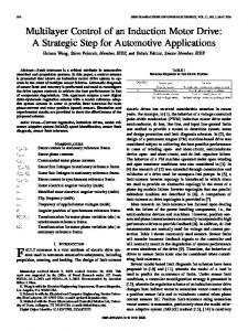
Fig. 17. Superposition of critical angular intervals and icosahedron histogram for third-order tessellation.
the total air gap and consequently on the thickness of the rotor external layer. Its use in the developments leading to relation (18) is hence not straightforward and the result is quite complex. However, a graphical representation shows how the Carter factor manages a closer fit between the analytical and numerical results (Fig. 16). 2) Two-Layer-With-Teeth Rotor: The two-layer-with-teeth rotor is characterized by additional parameters, mainly: number, distribution, diameter, and shape of teeth. a) Number and Distribution of Teeth: As shown in the next section, the insertion of ferromagnetic teeth through the external layer leads to the best actuator performances. Nevertheless, it also introduces significant torque oscillations. To reduce these oscillations, a study detailed in [19] was performed on the influence of the number and distribution of teeth around the rotor. This study was carried out in three steps. First, the influence of the angular distance between rotor teeth on torque oscillations was analyzed on a 2-D structure [Fig. 14(b)]. This revealed critical intervals of angular distances for which torque oscillations becomes too significant. Next, particular 3-D teeth distributions were considered: teeth corresponding to the vertices of regular polyhedrons and their tessellations. For each of these, an angular spectrum was established: a kind of histogram showing, for all possible orientations
3-D structure used for numerical modeling.
of the rotor, the distribution of angular distances separating two consecutive teeth. These histograms reveal a series of peaks indicating the existence of some angular distances occurring more frequently than others. Lastly, these 3-D histograms and the critical intervals revealed by the 2-D study were superimposed (Fig. 17). In this way, it appeared that a tooth distribution corresponding to a sixth-order tessellation on an icosahedron avoids all critical intervals. b) Diameter of Teeth: Along with the number of teeth, their diameter determines the proportion tp of teeth on the rotor surface. As shown in [20], this proportion influences the actuator performances. Performed on a 2-D structure [Fig. 14(b)], this study was carried out by computing, for various tooth proportions tp, the external layer thickness given an optimal conversion parameter . Results obtained for 22 and 44 teeth (Fig. 18) indicate that the maximal value of the optimal conversion parameter is reached, in each case, for similar values of tooth proportion and external layer thickness. It thus seems possible to implement 2-D results in 3-D structures, where the number of teeth does not impose a constant angular distance between the neighboring teeth but a complete spectrum, as illustrated on Fig. 17. In order to confirm this assumption, some numerical simulations were performed on 3-D structures (Fig. 19). Results obtained for 252 teeth (Fig. 20) are conclusive. Indeed, the optimal value of the conversion parameter reaches a maximum for a steel ratio ranging between 30% and 40% and an external layer thickness close to 11 mm, as foreseen in the 2-D analysis.
DEHEZ et al.: DEVELOPMENT OF A SPHERICAL INDUCTION MOTOR WITH TWO DEGREES OF FREEDOM
2085
Fig. 20. Evolution of the optimal conversion parameter and the external rotor layer thickness with tooth proportion for 3-D structure. Fig. 22. Evolution of the optimal conversion parameter with the external rotor layer thickness.
Fig. 23. Fig. 21.
Inductor repartition around the spherical rotor.
Influence of the teeth’s shape on the conversion parameter.
c) Shape of Teeth: Shape of rotor teeth is another parameter influencing the actuator performances. Working on a 2-D structure like the previous one [Fig. 14(b)], we started from a rotor with 22 straight teeth, a tooth proportion tp of 50% and the corresponding optimal thickness of the external layer , 10 mm [Fig. 21(a)]. Keeping the same tooth proportion and the same external layer thickness, we reduced the tooth diameter deeper inside the rotor [Fig. 21(b)]. As observed, this modification involves a notable improvement of the conversion parameter . To confirm the advantage of wide-mouthed teeth we also determined the performances of a rotor with straight teeth characterized by a tooth proportion tp of 40%, with a diameter equal to the inside diameter of the wide-mouthed teeth, and the corresponding optimal thickness of the external layer , 11 mm [Fig. 21(c)]. 3) Two-Layer Versus Two-Layer-With-Teeth Rotor: A comparison between the two-layer and two-layer-with-teeth rotors was performed on the basis of the previously used 2-D structure (Fig. 14), looking for the best conversion parameter as a function of the thickness of the external layer rotor. As observed in Fig. 22, the conversion parameter can achieve values ten times higher in the case of the two-layers-with-teeth rotor. Let us note
too that the optimal values of the external rotor layer thickness are not the same in the two cases. IV. FINAL CONCEPT Although all the proposed concepts were not characterized, a first solution integrating stator and rotor elements as well as a bearing device has been developed. A. Stator One- and two-DOF inductors are complementary and can be used together. Indeed, when correctly arranged around the spherical rotor (Fig. 23), they allow us to maximize the actuation surface while preserving an access zone to the rotor for the motion transmission to the load. Since a laminated magnetic circuit [Fig. 4(b) and Fig. 7] is the best solution to optimize conversion efficiency, it is made from a solid material. This choice is necessary due to manufacturing difficulties that cannot be justified in the case of prototyping. B. Rotor In spite of the increased manufacturing difficulties, we decided on the two-layer rotor with wide-mouthed teeth because
2086
Fig. 24.
IEEE TRANSACTIONS ON MAGNETICS, VOL. 42, NO. 8, AUGUST 2006
Air bearing integration in (a) one- and (b) two-DOF inductors.
of its higher level of performance. As regards to the type of material, magnetic powders were dropped in favor of a solid material not only because of its higher manufacturability but also because of the equivalent level of performance that it shares with magnetic powders. Fig. 25.
Detail of fitting apparatus.
Fig. 26.
Prototype of two-DOF spherical actuator.
C. Bearings Bearings are a key element of the spherical actuator because the rotor must be allowed to turn freely in all directions while accurately maintaining its position between the inductors. Too significant friction would reduce the useful torque whereas bad positioning would require increasing the air gap thickness. Moreover, available space on the rotor surface being limited, the type of bearings and their load capacity have a direct impact on the surface remaining for actuation. Among the solutions allowing the guiding of spherical parts, we considered the use of carrying balls, universal mechanical wheels, castor wheels, sliding bearings, magnetic bearings and aerostatic bearings. After a characterization of these various solutions, we retained the aerostatic bearings mainly because of the possibility of integrating them directly into the inductors (Fig. 24). This integration affords many advantages. First, the entire surface available on the rotor can be exploited both for actuation and guiding. Next, air gap thickness can be strongly reduced. Last, various parts of the actuator are cooled by forced convection allowing an increase of the intensity of the currents circulating in inductors, and consequently, the actuator power density. D. Fitting In agreement with the selected setup (Fig. 25), the two-DOF inductor is the only one rigidly fixed to the structure. On the other hand, one-DOF inductors are linked to the structure via two compression springs and two traction cables. This is necessary to avoid a hyperstatic situation where a positioning default of the inductors or a form error of the rotor could lend to a system dysfunction. Spring compression and cable traction are then adjustable using screws in order to position the inductors around the rotor while leaving the inductors capable of adapting, e.g., to the form errors of the rotor. V. EXPERIMENTAL VALIDATION The experimental stage started with the development of a first prototype and a test bench intended to characterize it.
A. Prototype The choice of prototype materials and dimensions was based primarily on the results of the electromagnetic characterization. However, the stator sizing was performed on the basis of a scaling law developed by De Jong [21] for ac motors. This law specifies geometric dimensions, but also electric values such as leakage reactance, according to a characteristic parameter of the actuator. As previously suggested, aspects related to manufacturing also guided our choices, more so since we do not consider a mass production of the actuator. Lastly, the manufacturing of the prototype (Fig. 26) having slightly preceded some modeling results, a number of choices (mentioned in Table V) proved to be nonoptimal a posteriori. The diameter of the rotor teeth and the thickness of the external layer, for example, are far from the optimal values obtained by numerical modeling. B. Test Bench Since the torque developed by the actuator is weak, the test bench implements a principle minimizing friction of the measurement setup. It consists in placing the entire prototype out of balance around an axis, guided by two ball bearings, and maintaining it through a static torque sensor and a flexible coupling (Fig. 27).
DEHEZ et al.: DEVELOPMENT OF A SPHERICAL INDUCTION MOTOR WITH TWO DEGREES OF FREEDOM
2087
TABLE V PROTOTYPE PARAMETERS
Fig. 28.
Fig. 27.
Test bench.
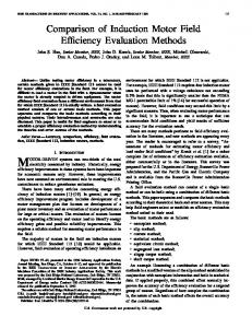
Loading of the actuator is obtained thanks to a dc motor and a friction wheel in contact with the spherical rotor. Supplied via a speed controller, the dc motor provided a point-by-point definition of the torque-speed characteristic of the actuator around one of its principal rotation axes. C. Measurements d) Torque-Slip Characteristic: This technique was applied to plot the torque-slip characteristic of the prototype for various frequencies: 25, 50, and 75 Hz (Fig. 28). For each of these, the supply current and the air gap thickness were fixed at 42 A t and 0.25 mm, respectively. A first observation relates to the values reached by the torque: 9 10 N m at 25 Hz and 4.5 10 N m at 75 Hz. These
Torque-speed characteristic of the prototype.
could seem particularly weak, but their order of magnitude is comparable with the predictions of the numerical model. A second observation concerns the shape of the characteristic around the synchronism speed (null slip) where it is comparable to a straight line. Contrary to classical induction motors, it appears that the slope of this line does not depend on the supply frequency. At this stage of the study, this particular evolution can be explained only via the importance of the skin effect both in the conducting external layer of the rotor and in the stator and rotor magnetic parts. A third and last observation relates to the torque value at synchronism speed. Indeed, contrary to the conventional situation, the torque is not zero at the synchronism speed, but for a value of the slip close to 0.2. This proves the presence of harmonic torque components due both to the boundary effect and the existence of a significant fifth harmonic in the evolution law of mutual rotor/stator inductances. This harmonic could be reduced by reconsidering the stator winding distribution, e.g., by using the traditional techniques of distributed windings. e) Electrical Efficiency: Parallel to the torque and speed measurements, the electrical efficiency was also determined through the observation of supply currents and voltages. Among the various tests carried out, the best efficiency was obtained for a supply frequency of 75 Hz. In these conditions, it barely reaches 1%! Compared to previous tests, carried out on intermediate prototypes, this dramatically low value of the efficiency is surprising. Indeed, a 15% efficiency has already been measured on a structure consisting of two one-DOF laminated inductors placed around a two-layer rotor. The air gap thickness was then 1 mm and the supply frequency 75 Hz. In order to identify the source of this degradation, the twolayer-with-teeth rotor was replaced on the last prototype by a two-layer rotor with an optimized external layer thickness of 0.5 mm. Comparing the torque-speed characteristic of this rotor with that of the two-layer-with-teeth rotor (Fig. 29) under simand 50 Hz), it clearly appears ilar supply conditions (42 that the rotor with teeth has a better conversion efficiency, 1.8 times that of the two-layer rotor. On this basis, the poor efficiency can be ascribed mainly to the solid material composing the magnetic circuits. At present, laminated circuits still constitute the best means of reducing both eddy current and hysteresis losses.
2088
IEEE TRANSACTIONS ON MAGNETICS, VOL. 42, NO. 8, AUGUST 2006
Fig. 29. Comparison between torque-speed characteristics of two-layer and two-layer-with-teeth rotors.
In conclusion, this study confirms both theoretically and experimentally the advantages of a rotor structure with magnetic teeth. It also shows the possibility of resorting to a 2-D study instead of a 3-D one when sizing the spherical rotor of the actuator. Further to this, it would now be interesting to show that the design rules applied to traditional cylindrical motors are also applicable. These rules could then be applied to simultaneously size the rotor and the stator. The only rule that will remain nontransposable to 2-D relates to the choice of the number and distribution of teeth around the rotor. This study also highlights the strong damaging effect of a massive material on the actuator performances, this choice however being justified by more practical considerations of manufacturing and integration of the aerostatic bearing. This reveals the need for a global integrated approach simultaneously taking into account electrical, mechanical and manufacturing aspects.
VI. CONCLUSION ACKNOWLEDGMENT The development of actuators dedicated to the applications for which they are intended is becoming more and more frequent. This trend can be explained primarily by the increasing possibilities afforded by computing and modeling tools. Within this context, the development of a spherical-shaped motor actuated with an unlimited angular range along two degrees of freedom was fully justified. The foremost application of this actuator concerns omnidirectional mobile robots [2] and [10], but it could also be used in industrial conveyors to orientate and redirect products along the line. In accordance with the structure of a classical design process, this paper first presents the various solutions allowing one to drive a sphere by induction. Several stator structures, one and two-DOF inductors, and several rotor structures, one-layer, two-layer and two-layer-with teeth rotors are thus described. For each of these, some points of detail, such as the shape and the material of the magnetic circuit of the inductors, are also discussed. Secondly, the various rotor structures are characterized on the basis of a parameter reflecting the electromechanical conversion efficiency of the actuator. Through analytical and numerical modeling, the influence of the main rotor parameters on the actuator performances are studied and commented. The various rotor structures are also compared to prove the superiority of a rotor with teeth. For the latter, the validity of a 2-D model in determining the size of the teeth and the thickness of the external layer of the rotor ensuring the best conversion efficiency are established. Finally, a global solution integrating the electrical and mechanical aspects of actuation and guiding is presented. In this solution, the actuation is obtained thanks to four one-DOF inductors and one two-DOF inductor arranged around a two-layerwith-teeth rotor. The guiding is achieved using aerostatic bearings directly integrated into the inductors. Along with the details of the fitting apparatus, the test bench used to measure the torque-speed characteristic and the electric efficiency of a first prototype is described. The main result of this experimental stage concerns the low value of electrical efficiency. This is explained primarily by the use of a massive stator in which the eddy current and iron losses are very significant.
This work was supported by convention no. 9713514 with the Walloon Region and the Belgian Program for Inter-University Attraction Poles initiated by the Belgian State-Prime Minister’s Office—Science Policy Program IUAP-IV-24 and IAP-V-06. REFERENCES [1] B. Bederson, R. Wallace, and E. Schwart, “A miniature pan-tilt actuator: The spherical pointing motor,” IEEE Trans. Robot. Automat., vol. 10, no. 3, pp. 298–308, Jun. 1994. [2] M. West and H. Asada, “Design of ball wheel mechanisms for omnidirectional vehicles with full mobility and invariant kinematics,” J. Mech. Des., vol. 119, pp. 153–161, 1997. [3] M. Kant, “Machines with two or three mechanical degrees of freedom” (in French), Rev. Générale l’Electricité, vol. 10, pp. 642–647, 1998. [4] J. Wang, G. Jewell, and W. Howe, “Modeling of a novel spherical permanent magnet actuator,” in Proc. IEEE Conf. Robotics and Automation (ICRA’97), New Mexico, 1997, pp. 1190–1195. [5] R. Roth and K.-M. Lee, “Design optimization of a three degrees-of-freedom variable reluctance spherical wrist motor actuator,” Trans. ASME J. Eng. Ind., vol. 117, pp. 378–388, 1995. [6] K.-M. Lee and C. Kwan, “Design concept development of a spherical stepper motor for robotic application,” IEEE Trans. Robot. Automat., vol. 7, no. 1, pp. 175–181, Feb. 1991. [7] K. Davey, G. J. Vachtsevanos, and R. Powers, “The analysis of fields and torques in spherical induction motors,” IEEE Trans. Magn., vol. MAG-23, no. 1, pp. 273–281, Jan. 1987. [8] K. Takemura and T. Maeno, “Design and control of an ultrasonic motor capable of generating multi-DOF motion,” IEEE/ASME Trans. Mechatron., vol. 6, no. 4, pp. 499–506, Dec. 2001. [9] L. Ferrière, G. Campion, and B. Raucent, “ROLLMOBS: A new drive system for mobile robot,” Robotica, vol. 19, pp. 1–9, 2001. [10] B. Dehez, D. Grenier, and B. Raucent, “Two-degree-of-freedom spherical actuator for omnimobile robot,” in Proc. IEEE Conf. Robotics and Automation (ICRA’02), Washington, DC, 2002, pp. 2381–2386. [11] G. Kaminski and W. Przyborowski, “Spherical electrical motor,” (in Polish), Patent PL245109. [12] M. Persson, P. Jansson, A. G. Jack, and B. C. Mecrow, “Soft magnetic composites based—Use for electrical machine,” in Proc. 7th Int. Conf. Electrical Machines and Drives, Durham, U.K., 1995, IEE Conference Publication no. 412, pp. 242–246. [13] P. Jansson, “Advances in soft magnetic composites based on iron powder,” Proc. Soft Magnetic Materials, Apr. 1998. paper 7. [14] A. G. Jack, B. C. Mecrow, P. G. Dickinson, D. Stephenson, J. S. Burdess, N. Fawcett, and J. T. Evans, “Permanent-magnet machines with powder iron cores and pressed windings,” IEEE Trans. Ind. Appl., vol. 36, no. 4, pp. 1077–1084, Jul.-Aug. 2000. [15] B. Dehez, V. Froidmont, D. Grenier, and B. Raucent, “Design and modeling of a two degrees of freedom spherical actuator with unlimited angular range,” in Proc. 2nd Int. Conf. Recent Advances in Mechatronics (ICRAM’99), Istanbul, Turkey, pp. 522–535.
DEHEZ et al.: DEVELOPMENT OF A SPHERICAL INDUCTION MOTOR WITH TWO DEGREES OF FREEDOM
[16] B. Dehez, V. Froidmont, D. Grenier, and B. Raucent, “Design of an actuator with spherical rotor and unlimited range (in French),” in Proc. Conf. Conversion Electromécanique Directe, Cachan, France, 1999. [17] B. Dehez, V. Froidmont, D. Grenier, and B. Raucent, “Design, modeling and first experimentation of a two-degree-of-freedom spherical actuator,” Robot. Comput.-Integr. Manufact., vol. 21, pp. 197–204, 2005. [18] G. W. Carter, Electromagnetic Field in Its Engineering Aspects: Longmans, 1954. [19] G. Galary, B. Dehez, and D. Grenier, “Optimization of a two-degree of freedom spherical actuator,” in Proc. 2004 Int. Conf. Electrical Machine (ICEM’04), Cracow, Poland, 2004. [20] G. Galary, B. Dehez, and D. Grenier, “Advanced study of a two-degree-of-freedom asynchronous spherical actuator,” in Int. Conf. Modeling and Simulation of Electric Machines, Converters and Systems (ELECTRIMACS’05), Hammamet, Tunisia, 2005. [21] H. C. J. De Jong, A. C. Motor Design With Conventional and Converter Supplies. Oxford, U.K.: Clarendon, 1976, p. 106.
2089
Grzegorz Galary was born in Wroclaw, Poland, in 1972. He received the Ph.D. degree in electrical engineering from the Université catholique de Louvain, Louvain-la-Neuve, Belgium, in 2005. Since 2005, he has been an examiner at the European Patent Office, The Hague, Holland.
Damien Grenier was born in Rouen, France, in 1965. He received the Ph.D. degree in electrical engineering from the Ecole Normale Supérieure de Cachan, France, in 1994. During 1994–1996, he was Post-Doctoral Researcher at the Ecole de Technologie Supérieure, Montréal, QC, Canada. In 1996, he joined the Université catholique de Louvain, Louvain-la-Neuve, Belgium, were he took part in the creation of the Center for Research in Mechatronics. Since 2005, he has been Professor in the Department of Mechatronics of the brittany site of the Ecole Normale de Cachan. His research interests are modeling and design of electromechanical systems.
Manuscript received October 21, 2005; revised January 24, 2006. Corresponding author: B. Dehez (e-mail: [email protected]).
Bruno Dehez was born in Uccle, Belgium, in 1975. He received the degree in electromechanical engineering and the Ph.D. degree from the Université catholique de Louvain (UCL), Louvain-la-Neuve, Belgium, in 1998 and 2004, respectively. He is currently Senior Researcher in the Centre for Research in Mechatronics (CEREM) at UCL. His research interests are in the field of dedicated actuator design.
Benoit Raucent received the degree in mechanical engineering from the Université catholique de Louvain (UCL), Louvain-la-Neuve, Belgium, in 1984, the DEA in robotics and automation from the Université des Sciences et Techniques du Languedoc, Montepllier, France, in 1985 and the Ph.D. degree from UCL in 1990 in the field of robot dynamic identification. Since 1985, he has been an Associate Professor and since 2000, Professor in the Department of Mechanical Engineering, Université catholique de Louvain. His research interests include factory automation, design for assembly, design of mobile robots, and design of micro-machines.