However unlike [1], we introduce a 3-bit feedback sys tem that conveys the ... each timeslot, and the transmitters adjust their phase to reach ... uniformly distributed random variables in the range (-]f, ]fl. We ... The BS broadcasts this feedback to all transmitters. ... measures the received signal strength and direction and mag.
DISTRIBUTED TRANSMIT BEAMFORMING BASED ON A 3-BIT FEEDBACK SYSTEM Wayes Tushar and David B. Smith Research School of Information Science and Engineering T he Australian National University National Information and Communication Technology Australia
��
SNR and motion direction feedback
ABSTRACT
A distributed transmit beamforming technique is developed for both a static and a time-varying channel in a wireless sen sor network. This algorithm is based on an iterative procedure that synchronizes the transmitters to send a common message signal coherently to the receiver, using a 3-bit feedback in each timeslot. Results show that the received power increases quadratically with number of transmitters, and there is a sub stantially improved performance over a I-bit feedback system and system without feedback.
eceiver
b,b,bo
e'"
bl=l, b2=O
1. INTRODUCTION
Distributed beamforming is a technique in which two or more radios cooperatively form a virtual antenna array and obtain diversity gains from channel diversity and array gains from increased directivity [1]. The gain from the distributed beam forming is large and the communication distance can be con siderably increased by adding more sensors [2]. Depending on the communication constraints several interesting models have been proposed and analysed in the field of distributed beamforming. The performance of collaborative beamform ing using the theory of random arrays is analysed in [3]. In [4] the authors proposed a blind beamforming technique us ing only the measured sensor data for signal enhancement and space-time filtering. Collaborative beamforming with Gaus sian distributed sensor nodes was discussed in [5]. A scalable mechanism for achieving phase synchronization in a com pletely distributed fashion based only on the power has been discussed in [6]. Further distributed receive beamforming in the literature includes [7, 8]. An energy efficient MAC and routing protocol for a distributed beamforming physical layer, for a single data packet transmission is proposed in [9]. In this paper our concentration is on the model proposed in [1]. Our work is closely related to [1] in the sense that we also consider a closed loop synchronization system [10] for both static and time-varying channel and measure the received sig nal strength at the receiver, and then send a feedback in each timeslot to the transmitter based on the receive signal strength (RSS). However unlike [1], we introduce a 3-bit feedback sys tem that conveys the information of RSS and also the direc tion of the motion of the receiver relative to the transmitter in
Sensors forming array
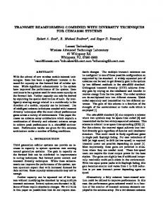
Fig. 1. System Model for 3-Bit Feedback System
each timeslot, and the transmitters adjust their phase to reach an optimum RSS at the receiver. It is shown that the received signal strength increases quadratically with the number of an tennas in the transmitter.
2. SYSTEM MODEL
The communication model considered in this paper as shown in Fig. 1 is similar to that used in [1], but in addition the re ceiver is considered to be mobile here. The transmit network consists of N transmitters that cooperatively transmit a com mon message signal met), by modulating it with an RF carrier signal. All transmitters are frequency locked to the carrier sig nal using master-slave architecture [2]. Therefore all carrier signals transmit at the same frequency Ie and there is no fre quency offset between the transmitters. Due to the unknown propagation delay in the master-slave architecture, there is an arbitrary phase difference between the transmitters. There fore the carrier signal of transmitter i can be written as: (1) where � indicates the real part and 'Yi is the phase offset. Transmitter i modulates the message signal m(t) with carrier
Ci, after rotating the angle by Oi, and hence transmits the mod 2 ulated signal Si(t) TR(m(t) ej8;e(j 7r!ct+j,,/;)) on the wire WieN;, less channel. If the channel to the receiver is gi where 'lfJi is the phase of the beamforming weights, the total received signal is: =
=
r(t)
=
2 TR m(t) ej 7rfct
(
t WieU,,/;+j8;+N;l )
(2)
�=l
So the power of the received signal is given by:
3.2. Proposed 3-bit feedback algorithm
In our 3-bit feedback system the receiver sends three bits, b2, bl and bo, as feedback to the transmitters at the end of each timeslot, the amount of time in which the transmitter add the phase perturbation and transmit the signal and the receiver measures the received signal strength and direction and mag nitude of motion and sends 3-bit feedback to the transmitters accordingly. The bit bo serves the same purpose as the I-bit feedback of [1]. The bl and b2 convey the information of the direction of motion of the receiver. If b2 EB bl 0, where EB implies the exclusive-or operation, then the receiver is consid ered stationary with respect to the transmitters and the chan nel is static as in [1]. If b2 EB bl 1 then the transmitters assume that the receiver is moving either towards the trans mitters or away from them, therefore a time-varying channel, and the transmitters adjust the phase of the signal based on the value of bl and bz. In this algorithm bl 1 (b2 0) in dicates that the receiver is moving away from the transmitters and bl 0 (b2 1) indicates vice versa. The relative motion between the receiver and transmit ter changes the frequency of the received signal by shifting the frequency by an amount ±b.f [11]. If the carrier fre quency is fe , then the received signal frequency is (fe + b.f,) if the receiver is moving towards the transmitters (b2 1), or (fe - b.f) if moving away from the receiver (bl 1). This phenomena has been incorporated in our algorithm to consider the time-varying channel for receiver motion with respect to the transmitters. The frequency or Doppler shift due to moving receiver's motion, and angle of arrival of plane wave, follows the equation [11]: =
(3)
=
where ¢i "Ii + Oi + 'lfJi, denotes the power of received sig nal from transmitter i. The power in (3) is maximized when the signals from the transmitters are received coherently. The received power in equation (3) changes randomly due to the random nature of the time-varying channel. In this model, like [1], the phase rotations from the transmitters are adjusted to achieve phase coherence at the receiver. Assumptious: The received phase angles ¢i are com pletely unknown before the feedback control algorithm is ex ecuted and as in [1], the initial values of ¢i are modeled as uniformly distributed random variables in the range (-]f, ]fl. We assume that the angle of arrival of plane wave does not vary between timeslots if the receiver is in a stationary state. We also assume that there are only a even number of arrays deployed in the transmitter. =
=
=
=
=
=
=
3. FEEDBACK CONTROL PROTOCOL FOR PHASE
(4)
SYNCHRONIZATION 3.1. I-bit feedback algorithm
=
In [1], the transmitter keeps a record Obest,i[n] of the best known value of its phase perturbation, and the receiver keeps an estimate Zbesdn] of the best achievable RSS. In the next (n + 1) timeslot, each transmitter generates a random phase perturbation Oi from some probability distribution 10 (Oi) , and transmits its message signal with an incremental phase rota tion Oi. Upon receiving the signal Y[n+ 1]
where fd b.f is the Doppler shift, A is the wavelength of t the wave, an is the angle of arrival at n h timeslot and v is the velocity of the receiver. The effects of angle of arrival and velocity of receiver on the received signal strength are considered together in this algorithm. The algorithm proposed in this paper is described below in a stepwise fashion:
=
I
l L�l ieN;[ + l a
n
l
,
the BS generates a single bit of feedback '1' if the received signal strength in the current timeslot is better than the esti mated best Zbesdn], and '0' otherwise. The BS broadcasts this feedback to all transmitters. If the feedback bit is '1', the BSS updates its value of Zbest[n + 1] with the new measured RSS, and the transmitters update the phase rotations to retain the perturbation Oi; otherwise the BS discounts the estimated best RSS Zbest[n] by a factor p < 1 to reflect the expected de terioration due to channel variation, and the transmitters dis card the perturbations Oi. The process is repeated in next timeslot.
1. The receiver measures RSS Y[n] at each timeslot nand keeps the record Ybest[n] of its best previously observed RSS: (5) Ybest[n] max Y[m] =
m=:;n
where V n d[m] in (6) is added to randomize the re ceived power of time-varying channel on that timeslot. This variation in the receive power is assumed Gaus sian random due to time-varying nature of the channel, and is only applicable if there is any movement in the receiver i.e.(b1 EB b2) 1.
ra
=
3-bit feedback system, for both static and time-varying chan nels is made. The model is simulated for different number of antennas at the transmitter (N 100,150,200,250) for a time-varying-channel, and it is shown that the received signal strength increases quadratically with the number of antennas in the array. The time span between each timeslot could have different specification according to application but one possi ble specification is 577 microseconds between each timeslot as for the GSM (Global System for Mobile Communications) specification [12].
Table 1 Feedback From Receiver to Transmitter
b,b,bo
Type ofchanncl
Receive Signal Strength
000
Y[n+I]< Y[n+l]> Y[n+I]< Y[n+I]> Y[n+I]< Y[n+I]> Y[n+I]< Y[n+I]>
001 01 0 01 1 1 00 101 110 III
Y[n] Y[n] Y[n] Y[n] Y[n] Y[n] Y[n] Y[n]
b2 0) b2 0) The channel is tillle varying (hi EB b2 I) The channel is time varying (hi EB b2 I) The channcl is time varying (hi EEl b2 I) The channel is time varying (hi EB b2 I) The channel is static (b] EB b2 0) The channel is static (hi EB b2 0) The channel is static
The channel is static
(hi (hi
EB
::::
EB
;;;;
=
::::
::::
::::
=
:::: ::::
2. At timeslot n + 1, each transmitter generates a random phase perturbation 8i which can be changed with time and depends on the value of the feedback bits b1 and b2. The phase perturbation added to the phase of the original signal at each timeslot is written as:
¢[n + 1] ¢[n + 1]
3.
=
=
¢best,n + 8i
¢best ,n + 8random[n + 1] + (b1 EB b2)(b1 - b2)8per.
(7)
(8)
where ¢best ,n is the phase for which equation (5) is satisfied and 8per is a randomly generated perturbation chosen uniformly randomly in the range [-7r,7r] that added to the phase of the transmitted signal depending on the value of b1 and b2• 8random is the phase per turbation generated uniformly randomly in the range [-7r /20,7r /20] that is added to the phase at each times lot to reach the optimum signal-to-noise ratio. The receiver measures the received signal strength and generates three bits of feedback depending on RSS and the direction of motion of the receiver. There can be 23 8 different types of feedback where each indicates different states of receiver motion and signal strength to the transmitters. They are summarized in Table I. The transmitter receives the feedback and generates a random phase perturbation 8i. 8random is generated by the transmitters and added to 8i in each timeslot regard less of the value of b1 and b2, but 8per is generated and added to the phase only when b1 EB b2 1. The receiver updates its value to Ybest[n + 1], and the transmitters update the phase to ¢best,dn + 1], for max imum receive signal strength, to retain the perturbation if the feedback bit bo 1, and discard them otherwise. The process is repeated in the next timeslot. =
4.
=
5.
=
6.
4. SIMULATION AND RESULTS
In order to verify the validity of this distributed beamforming strategy, the algorithm described in Section TIl is simulated. Simulations were carried out for various conditions, and per formance comparison between a I-bit feedback system and a
For a uniformly weighted linear array the largest sidelobes are approximately 24 percent down from the peak value.The presence of sidelobes means that energy is radiated in un intended directions, and due to reciprocity, the array is also receiving some energy from incorrect directions [13]. Here Kaiser Bessel weights, determined by w(k)
=
10 [naVl-(�)2] , 10 [ na]
where N is the total number of antennas in the array and 1,2,....,N/2, are used as steering vectors to compen sate the effects of the channel on signal. The received sig nal strength is normalized by modifying the weights so that E( Wi) 0, and these weights are considered fix for all times lots. Though the weights are normalized to ° by combining both positive and negative valued weights, the signal strength is considered positive by taking the magnitude.
k
=
=
Depending on the direction of the motion of the receiver the frequency shift is positive (causing a increase in frequency) if the receiver is moving towards the transmitters (b2 1 and b1 0) and shift is negative if the receiver is moving away from the transmitters (b2 ° and b1 1) [11]. Depending on the value of the bits b1 and b2, the compensation of the phase shift is made according to equation (8). =
=
=
=
In Fig. 2 the power received for various number of an tenna elements at the transmitter shows that the power in creases as the number of antennas in the array increase. So the expected received signal strength at any number of times lots is a non decreasing function of N, the number of trans mitters [1]. To show how the received power scales with the number of transmitters, the stable received power for differ ent number of transmitting antenna elements (Fig 2) is plotted against the number of antenna elements. Using basic fitting tool from MATLAB, a resultant curve is compared with the original figure in Fig 3 and it is shown that the power scales quadratically with the number of antennas at the transmitter in accordance with an established phenomenon [10], this is given by RSS -0.00047N2 + 0.41N + 9.3. =
For a time-varying channel the channel phase response changes in time due to the relative motion of the receiver and transmitters, and also due to Doppler effects from moving scatterers . Their channel variation occurs in the received sig nal, and channel variation causes the transmitted signal to lose coherence over time. As a result the received signal strength decreases on average [1]. Since in the time-varying channel the received signal strength changes randomly due to the ran-
9o ,-
50 r---,----r--�--r_--._--_.--_.�� --._--_.----,---.---_.--�
45
80
Iii � 70 �
g>
'" '"
a:: 35
60
�
�
:; C>
50
.. c C>
40
�
30
..
25
iii
iii 40
c C>
iii
..
3-bit feedback typical value---____ ----'...
mean value
20
10 ° L- -- � ----� --- � --�� --- � --�� --�� �� 0 400 700 100 300 600 200 500 800 Timeslot
Fig. 2. Received Power for Different Number of Antenna
N
Fig. 4. Comparison of 1-bit feedback system, 3-bit feedback
system and system without feedback for time-varying channel with N=100 transmitters
in the Array as a function of time
dom behavior of the channel, the received signal strength is randomized here by adding a random variable to RSS in ev ery timeslot as in equation (6). The random variable is added to RSS only when the channel is behaving as time-varying, that is bl EB b2 1, and the RSS remains the same for static channel (RSS without any randomness). =
FigA shows the comparison of RSS of the proposed 3-bit feedback system for a time-varying channel using the phase perturbation ( !8( Ji) t'Vuniform[ -7r /20, 7r /20]) for N 100, and the 1-bit feedback system [1] for the same situation. The graph for both mean value for 200 iterations, and the values for a typical iteration is given. In case of time-varying chan nel, our proposed 3-bit feedback system gives substantial im provement in performance. Fig. 4, demonstrate this large =
performance gains of the 3-bit feedback system over the 1bit feedback system and system without feedback . Whereas the 1-bit feedback system has an instability in receive signal strength, the RSS for the 3-bit feedback system has a stable increase towards its optimum value. There is substantial dif ference between the mean value of receive signal strength of the 3-bit and the 1-bit feedback system in FigA. Compar ing the mean RSS of the 1-bit feedback system with the 3-bit feedback it is observed that the RSS of the 3-bit feedback sys tem is twice that of the 1-bit feedback for timeslot 600. It is even more at timeslot 800 (at steady state). In case of the system without feedback there is no improvement in RSS and there are large fluctuations observable in the received signal strength.
85 ,-------,--, 80
Y
=
- 0.00047'N2 + 0.41'N + 9.3
Iii 75 '" �
&
70
E!
65
=
c
�
.. c C>
-- RSS - - -
'iii 60
quadratic
�
.;; "
&!
55
150 No of Transmitters
Fig. 3.
ments
Fig. 5, which shows a comparison of the feedback sys tems for a static channel, uses the same parameters for phase perturbation, generating mean, and N 100 as FigA, and which shows a typical iteration. The response of the system without feedback is also shown here. Fig. 5 shows that the 3-bit feedback system converges in almost the same manner as the 1-bit feedback system with a slight higher value at satu ration. From Fig. 5 at timeslot 150 the RSS of the 3-bit feed back system shows an improvement of 11.2 percent over the I-bit feedback system. Though there is no significant random perturbation in received power from one timeslot to another in a static channel, there is some minor phase perturbation of the received signal which the 3-bit feedback accounts for, which could be due to movement of scatterers. The system without feedback can not provide any satisfactory result, because the received signal gain for system without feedback is negligible compared to a I-bit and 3-bit feedback system.
200 (N)
250
Relation between received power and antenna ele
40 ,-----�--_.--,_--� mean 3-bit feedback
35
� 0::
[3] 30
�
g,
� u;
25
"iii 20
[4]
c CI
iii '"
> 'iii
15
...
�
10
5
I
I
.J
I'
�mean without feedback
,
,,-
typical without feedbck
[5]
O'L -----��----�----�------�----� 200 250 50 o 100 150 Timeslot
Fig. 5. Comparison of I-bit feedback system, 3-bit feedback
system and system without feedback for static channel with N=l00 transmitters
5. CONCLUSION In this paper it is shown that distributed beamforming using 3-bit feedback gives substantial improvement in performance for the time-varying channel due to receiver's motion, and that the power received at the receiver terminal is a non de creasing function of N and varies quadratically with N. For future investigation, it remains an important task to define a method to track received power as receiver velocity changes continuously. Including the effect of a given antenna radia tion pattern in the system would also be worthwhile. Finally the derivation of a analytical solution considering the effect of feedback delay is an open problem for future work.
[6]
[7]
[8]
[9]
6. ACKNOWLEDGEMENT [10] The authors would like to thank National Information and Communication Technology (lCT) Australia (NICTA). NICTA is funded by the Australian Government as represented by the Department of Broadband, Communications and the Dig ital Economy and the Australian Research Council through the ICT Centre of Excellence program.The authors also thank Md. Tofazzal Hossain of NICTA for his cordial assistance in writing this paper.
[11]
[12]
7. REFERENCES
[1] G. Barriac, R. Mudumbai and U. Madhow, "Dis tributed Beamforming Using 1 Bit Feedback System, " in Proceedings of Allerton Conference on Communica tion Control and Computing, 2006, pp. 1020-1027. [2] R. Mudumbai, G. Barriac and U. Madhow, "Distributed Beamforming for Information Transfer in Sensor Net-
[13]
works, " in Proceedings of International Symposium on Information Processing in Sensor Networks, 2004, pp. 81-88. H. V. Poor, V. Tarokh, H. Ochiai and P. Mitran, "Collab orative Beamforming for Distributed Wireless Ad Hoc Sensor Networks, " IEEE transection on Signal Process ing, vol. 53, no. 11, pp. 4110-4124, Nov. 2005. C. W. Reed, D. Chen, Kung Yao, R. E.Hudson and F. Lorenzelli, "Blind Beamforming on a Randomly Dis tributed Sensor Array Sytem, " IEEE Journal on Selected Areas in Communication, vol. 16, no. 8, pp. 1555-1567, Oct. 1998. M. F. A. Ahmed and S. A. Vorobyov, "Collaborative Beamforming for Wireless Sensor Networks with Gaus sian Distributed Sensor Nodes, " IEEE Transactions on Wireless Communications, vol. 8, no. 2, pp. 638-643, Feb. 2009. U. Madhow, R. Mudumbai, J. Hespanha and G. Bar riac, "Scalable Feedback Control for Distributed Beam forming in Sensor Networks, " in Proceedings of Inter national Symposium on Information Theory, 2005, pp. 137-141. J. Elson, H. Wang, D. Maniezzo, R. E. Hudson, K. Yao, J. C. Chen, L. Yip and D. Estrin, "Coherence Accoustic Array Processing and Localization on Wireless Sensor Networks, " Proceedings of the IEEE, vol. 91, pp. 11541162, Aug. 2003. C. W. Reed, D. Chen, T. L. Tung, K. Yao, R. E. Hudson and F. Lorenzelli, "Array Signal Processing for a Wire less MEM Sensor Network, " in Proceedings of IEEE Workshop on Signal Processing Systems, Oct. 1998, pp. 11-20. S. A. R. Jafri, D. Koutsonikolas and C. Hu, "Energy Efficient MAC and Routing Design in Distributed Beamforming Sensor Networks, " in Proceedings of In ternational Conference On Emerging Networking Ex periments and Technologies, 2007. U. Madhow, R. Mudumbai, D. R. Brown III and H. V. Poor, "Distributed Transmit Beamforming: Chal lenges and Recent Progress, " IEEE Communication Magazine, vol. 47, pp. 102-110, Feb. 2009. T. S. Rappaport, Wireless Communications Principles and Practice, United States of America:Prentice Hall PTR, 1997. c. V. Olgaard and S. Yeung, "GSM Transceiver With Time Division Duplexed Operations For Receiving Data, Monitoring Signal Strength and Transmitting Data During A Single Time Frame", US Patent 6757261, June 29, 2004 F. Gross, Smart Antennas for Wireless Communications with MATLAB, McGrew-Hill, 2006.