3D OBJECT RECOGNITION USING OCTREE MODEL AND FAST SEARCH ALGORITHM Young Jae Lee∗, Ajith Abraham†, Dong Hwa Kim‡
Abstract: This paper presents a new approach to 3D object recognition by using an Octree model library (OML) I, II and fast search algorithm. The fast search algorithm is used for finding the 4 pairs of feature points to estimate the viewing direction uses on effective two level database. The method is based on matching the object contour to the reference occluded shapes of 49, 118 viewing directions. The initially bestmatched viewing direction is calibrated by searching for the 4 pairs of feature points between the input image and the image projected along the estimated viewing direction. At this point, the input shape is recognized by matching it to the projected shape. The computational complexity of the proposed method is shown to be O(n2 ) in the worst case, and that of the simple combinatorial method of O(m4 , n2 ), where n and m denote the number of feature points of the 3D model object and the 2D object, respectively. Key words: 3D object recognition, octree model, pattern analysis Received: March 20, 2009 Revised and accepted: February 10, 2010
1.
Introduction
Computer technology has changed remarkably, having a positive influence on the image processing community, such as computer vision, pattern recognition and image understanding, which process a huge amount of data [1-11]. At the same time, computer vision technology has also advanced rapidly. Computer vision gathers physical elements of the real world, based on the data that are taken through a variety of sensors, and carries out optical recognition that describes or classifies an object with those elements, which are necessary for a computer to make a ∗ Young Jae Lee Jeonju University, 1200 Hyo Ja Dong Wansan-Gu Jeonju Jeonbuk 560-759, Republic of Korea, E-mail:
[email protected] † Ajith Abraham – corresponding author Machine Intelligence Research Labs (MIR Labs), Scientific Network for Innovation and Research Excellence, P. O. Box 2259, Auburn, Washington 98071-2259, USA, http://www.mirlabs.org, E-mail:
[email protected] ‡ Dong Hwa Kim Department of Instrumentation and Control Engineering, Hanbat National University, 16-1 San Duckmyong-Dong Yuseong-Gu, Daejon 305-719, Republic of Korea
c °ICS AS CR 2010
359
Neural Network World 3/10, 359-369
decision. Several 3D object recognition techniques have been tried: affine invariant image [4], object silhouettes [5], object attributes [6] and shape from the X technique using movement information, stereo vision that draws 3D depth information from a stereo image taken with two cameras, range information recognition, and so on. But correct 3D description is not easy and a matching process is very complicated; therefore, the wide use of 3D optical equipment has been seriously restricted. An object in the 3D coordinate system may have a completely different 2D image according to the direction an observer’s eye is located. If a 2D shape recognition technique is applied, a standard model database for all directions must be constructed. The size of the database for recognition and matching increases tremendously and requires a considerable amount of time to recognize the object. In order to solve this problem, Object Centered Models that use fewer 2D images to describe a 3D object have been proposed. One of them, an octree Model [1-3], is known for its efficient data structure and a detailed contour description method [3]. An octree model has excellent spatial division information as compared with the general spatial division method [7]. The general method uses division angle according to latitude and radius. So division data is different according to objects’ shape, after all the data structure is very complex, but octree model has regular division data in 3D coordinates. To recognize a 3D object, a 3D object is abstracted from a 2D object, which is actually an image centered on an observer, and then compared to the octree of a standard 3D object. Only a partial recognition is possible for the limited information from the 2D image. In short, it is impossible to recognize a 3D object with a single 2D image. Therefore, it is necessary properly to project a standard 3D object to the 2D field and match it with a given 2D image from the opposite angle. In this paper, we presume that images are projected in parallel, and propose a fast 3D object recognition technique, based on Chien and Aggarwal’s method [4], which matches feature points between a 3D image and a 2D image. First, corresponding feature points are searched for between a 2D input image and the geometrical feature points of a model 3D image. 3D space is equally divided into 49 (octree model library I) or 118 (octree model library II) standard viewing directions, and the search process is accelerated, using 2D image information from these angles. A 2D input image is synthesized for the calculated viewing direction. Finally, the recognition process is completed through the last verification which checks image matching with the input image. A parallel projection can disregard an observational error if a camera is located at a long distance, compared to the size of an object. Also, automatically calculating the shooting angle and relative location of a 3D object provides great assistance. Therefore, this method can be used as a basic recognition algorithm for a 3D optical equipment.
2.
Octree and Projective Image Generation
A technique to make a model or effectively to describe a 3D object is a key factor to realize a computer vision system. The 3D describing technique is divided into two methods: volume description and surface description. Octree is a kind of volume description that extends a quadtree, a 2D object description method, for a 3D description. It is possible for an octree to describe a 3D object in a hierarchical 360
Young Jae Lee, Ajith Abraham, Dong Hwa Kim: 3D object recognition using. . .
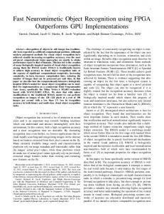
structure. Particularly, an octree can be generated automatically from three orthogonal 2D images with a volume intersection algorithm [2], while the 2D object image from a random viewing direction can be composed from octree structure by adding surface information of a 3D object. Therefore, it can be used as an effective description method for 3D object recognition. An octree is generated by volume intersection algorithm, and the basic principles are as follows: Each node of the three orthogonal quadtree nodes is extended to the coordinate system of the node in the space; if the three nodes of the quadtree related to an intersected voxel in the 3D space, are all black nodes, the voxel is determined as an object node of octree, and if more than one node is white, it is not an object node. For all voxels in the 3D space, this process can be applied in layers, and the octree is generated automatically. The utility of the octree structure lies in the fact that it can significantly reduce the size of the database needed for image recognition, for it can compose the projected 2D image of a 3D object from a random viewing direction. The Multi-level boundary search algorithm [3] is used as a method to detect which surface belongs to the surface of an object among six surfaces of a voxel that corresponds to each node of the octree. Among the surface nodes, the node, whose value is negative when a normal surface vector is multiplied by a vector from a viewing direction, is the one that can be seen from the viewing direction. If the surface of the nodes is projected in parallel with the viewing direction, a projected 2D shape is produced. With the absolute values of multiplied vectors, the projected 2D image can be expressed in pseudo gray. Fig. 1 illustrates an example of the projected 2D image, seen from a random viewing direction and synthesized in pseudo gray.
Fig. 1 Example of synthesized 2D projected images.
3.
New Recognition Algorithm
The algorithm, proposed in this paper, finds contours through the segmentation of an input image, and extracts feature points. Also, it locates at high speed four distinctive feature points among the model images produced by the octree model, and detects the model image that is exactly similar to the input image. To verify the similarity, the viewing direction is calculated. The viewing direction model is 361
Neural Network World 3/10, 359-369
created with the octree and compared to the input image to determine whether they match each other. The 49 standard viewing direction models in the OML I (Please, refer to Fig. 2) is used first. If OML I is not able to find any matching points, there are 118 standard viewing direction models in the OML II.
Fig. 2 The Fast 3D object recognition algorithm and generating OML (octree model library) I, II. OML II is used to find matching instead. The database of these models is structured in two levels. The recognizing process is minimized so that it can guarantee fast searching. The matching reliability can also be increased with two different recognition processes using OML I and II.
3.1
Feature points extraction
A feature point is created by detecting the point where the curvature of the contour is highest in the locus. In a digital image, the change of an inclination angle is scattered requiring a smoothed k-cosine function to be used. If the vector from feature point m to feature point is n marked am,n , the k-cosine of contour point i is defined as follows: The k value must be properly chosen in accordance with the size and complexity of an object. In this paper, the scale-space filtering technique is used as an algorithm to solve this problem. The concave feature point has little probability to be seen from a viewing direction and its location is not settled in the space, and the convex feature point is exclusively taken into consideration. From the 2D feature point detected on the top, side and front images, the feature point of a 3D object is produced on the basis of the following principle. If the two 2D 362
Young Jae Lee, Ajith Abraham, Dong Hwa Kim: 3D object recognition using. . .
feature points Pi and QJ are extended on the viewing directions, and they cross each other, the intersecting point is the feature point of the 3D object. Therefore, the 3D feature points could be extracted from all the pairs of feature points Pi and QJ on the 2D image. The 3D feature point and the normal surface information of each octree node are added to the octree structure, and the basic database for the 3D object recognition is established. cos θik =
3.2
aik • bik . |aik | |bik |
(1)
Two-level Database Construction
The 3D space can be set on the rectangular coordinates x, y and z, fixing the size of each unit to 1. The axes of coordinates x, y and z can be divided at regular intervals of 1, 0.5, or even a smaller number. If the interval is set as 1, the values on coordinate x are -1.0, and 1, increasing by 1. If the same values are set on coordinates y and z, the number of cases is 27. After excluding the mirror images and the center coordinate (0,0,0), we have thirteen viewing directions. If the interval is set as 0.5, the values on the coordinates are -1, -0.5, 0, 0.5 and 1, and the number of cases is 125. Without any mirror images and a center coordinate, we have 49 viewing directions. More minutely, with 0.4 intervals, there are 216 cases, but we can reduce the number of viewing directions to 118. The 118-direction database is more efficient than the 49-direction database, but it takes more time to recognize these features. In summary, the fast search algorithm is used to search for feature points to minimize the amount of time necessary for this procedure.
3.3
Matching condition for four pairs of feature points
If the coordinates for 2D feature point P i and the 3D feature point pj corresponding to P i are (Xi , Yj ) and (xj , y j , zj ), the projection from pj to P i is expressed as follows: Xi = R11 xj + R12 yj + R13 zj + tx (2) Yi = R21 xj + R22 yj + R23 zj + ty . The converting relationship between 2D and 3D coordinate systems is expressed by the rotation matrix elements V12 = [R11 , R12 , R13 ] and V2t = [R21, , R22 , R23 ] the moving transformation element tx , ty . Therefore, with four pairs of feature points, the transformation formula can be calculated. This transformation formula is orthogonal, V1 • V2 = 0, kV1 k = c, kV2 k = c
(3)
so the set of four pairs of feature points is searched for to satisfy the following condition. If the set of 2D feature points {P1 , P2 , ...Pn } and the set of 3D feature points {p1 , p2 , ...pn } are given, the transformational relationship between 2D and 3D coordinate systems can be obtained by searching for the four pairs of feature points which satisfy both transformation formula (2) and (3). 363
Neural Network World 3/10, 359-369
3.4
Calculation of the viewing direction t
If the viewing direction on the observer-centered coordinates is expressed as [0, 0, 1] , the viewing direction on the object-centered coordinates are transformed as follows. If the transformational matrix R that transforms from being object-centered to observer-centered is expressed as R11 R12 R13 (4) R= R21 R22 R23 R31 R32 R33 = Rt (R is an orthogonal matrix) 0 R31 R11 R21 = R−1 0 = R32 = R12 × R22 . 0 R33 R13 R23 R
Vdir
−1
(5)
Therefore, if four pairs of feature points that corresponds to each other and satisfying formulae (2) and (3) are determined, the viewing direction can be found by the cross product of V1 and V2.
3.5
Finding the 4-point corresponding feature points
If the number of 3D and 2D feature points are m and n, the time to search for four pairs of matching pairs that satisfy formulae (2) and (3) is in proportion to O(m4 , n4 ) when a simple combination is used. In order to satisfy the formula (2) using four pairs of 2D feature points that correspond to four feature points from several 3D feature points, the 2D shape matching method calculates a relative location and a viewing direction. Taking into consideration the quantum effect on a digital image and its effect on noise, the following formula determines whether the formula (2) is satisfied or not, and there are also small constants and the values of 0.3 and 0.2 used respectively in the experiments. However, taking the quantization effect and noise into consideration, the following expression is used to evaluate digital images. kV1 k |V1 • V2 | h δ1 , 1 − δ2 h h 1 + δ2 . (6) kV2 k We have constructed a database of projected 2D images taken from a variety of directions, and now propose a new fast search algorithm from step (1) to step (5) that has the complexity of O(n2 ). Step (1): Obtain a pair of feature points {pi , pj } having the longest distance in the input image. Step (2): For all model images { Obtain three pairs of feature points {qk , qs } having the longest distance; Compute the average boundary point distance Davr of the contour points when {pi } and {pj } are matched to {qs } and {qk }, respectively; } Step (3): Let Im denote the model image associated with the minimum Davr ; 364
Young Jae Lee, Ajith Abraham, Dong Hwa Kim: 3D object recognition using. . .
Step (4): {Q(p1 ), Q(p2 ), · · ··, Q(pn )} denote a set of feature points of Im nearest to {p1 , p2 , · · ·, pn }; Step (5): For (x = 0; x < n − 1; x + +) { For (y = x + 1; y < n; y + +) { Let S2 = {pi , pj , px , py } denote a set of 4 points in the input image; Let S3 = {qk , qs , Q(px ), Q(px )} denote a set of 4 points in Im ; Compute V1 and V2 using Eq. (2); If (V1 and V2 satisfy Eq. (3)) { Compute the viewing direction using Eq. (5); Generate the 2D projected image using the octree; Compute Davr between the model and the input images; If (Davr < Threshold) Stop; } } } The matching ratio is calculated when {pi , pj } that exists at its longest distance among the feature points on the input image and the three pairs of {qk , qs } that exist at their longest distance among the feature points corresponding to the images of the model database, I1 , I2 , ·, ·, · are matched. The model image Im , whose matching ratio is highest, is determined in Step 2. The appropriateness of the model image is checked in Step 4 and Step 5. The reason to match three pairs {qk , qs } is because the farthest feature points could shift with minute changes in their viewing directions. In matching Step 5, the maximum number of the hypotheses, n(n−1) must be verified, and the complexity is O(n2 ). The reason to 2 match three pairs {qk , qs } is because farthest feature points could be shifted with minute changes in their viewing directions. As a criterion for matching, the average distance between the contour points of the input image and the model is used.
4.
Experiments
The feature points were determined using the input image of an object seen from a random viewing direction, while the matching points were calculated using OML I and II and the fast search algorithm.
4.1
Experiment 1
In Experiment 1, we checked matching, using the proposed algorithm and the input image is shown in Fig. 4(a). On the input image, there are some noises in the bottom left corner, which are caused by lighting. Fig. 4(b) shows the gray image of the input image. Fig. 4(c) identifies the contour feature points of the input image, the bottom left of which is more protruding than on the original image, affected by shadows. Fig. 4(d) illustrates the matching process, comparing the feature points of the input image with those generated with the proposed technique. After the final 365
Neural Network World 3/10, 359-369
Fig. 3 The model image I and II. matching, the contour image of the model is obtained, as illustrated in Fig. 4(e) and the full gray image in Fig. 4(f). The matching is quite successful, even though there are some shadow noises.
Fig. 4 The input image and the matching result of Experiment 1.
4.2
Experiment 2
On the input image of Experiment 2, an aliasing error occurs due to shadow noises and diagonal lines of the object shape. Indented noises are spread over the bottom left corner, caused by the noises and traits of the shape on the right. Fig. 5(b) is a gray image for the input image, and Fig. 5(c) is the image that represents contour feature points of the input image. The bottom left of it is more protruding than the original image, affected by shadows. Fig. 5(d) shows the matching process, comparing the feature points of the input image with those generated with our 366
Young Jae Lee, Ajith Abraham, Dong Hwa Kim: 3D object recognition using. . .
technique. After the final matching, contour image of the model is obtained, as illustrated in Fig. 5(e) and the full gray image Fig. 5(f). The result of matching we experimented with the proposed algorithm is quite successful, as illustrated in Fig. 5(e), even though there are some noises.
Fig. 5 The input image and the matching result of Experiment 2.
4.3
Experiment 3
On the input image of Experiment 3, the aliasing error is more obvious than in Experiment 2. As shown in Fig. 6(b), the gray image is distorted from the original image due to the shadow effect. We tried the algorithm of OML I, but the recognition was denied because the loci of feature points were moved far away (Fig. 6(d)). When the OML II is applied, the recognition results are as illustrated in Fig. 6(e). The viewing direction is calculated with the feature points of matching images, and the projected image of Fig. 6(f) is generated with octree model. It can be confirmed that the matching image is similar to the input image. Fig. 6(g) shows full gray image of Fig. 6(f). In Experiments 1 and 2, OML I is used to achieve correct matching, in spite of shadows and aliasing. In Experiment 3, a distortion by shadows is quite gross, and recognition couldn’t be processed, so OML II is used for matching. With two levels of the database, recognition can be more accurate.
5.
Conclusions
We have proposed an octree model for 3D object recognition in a single view under parallel projection. The octree model, hierarchical volume description of 3D object, may be utilized to generate projected image from arbitrary viewing directions, thereby providing an efficient means of the data base for 3D object recognition. In 367
Neural Network World 3/10, 359-369
Fig. 6 The input image and the matching result of Experiment 3. this paper, we have estimated a primary viewing direction by matching an input image with 2D object shapes projected from 49 or 118 standard viewing directions, and we present a fast search algorithm for finding the 4 pairs of feature points to estimate the viewing direction using geometrical information of these images. The two-level database is used in this research. Even if the first level model database with 49 standard viewing directions fails, the matching is still possible with the second level database of 118 viewing directions. The searching time is reduced to the minimum by using the fast search. The viewing direction is calculated from the four pairs of feature points, identified by the search. Our experiments confirm that a 3D object can be recognized at high speed, through the verifying process of matching an input image with a shape, projected from a calculated viewing direction. The 3D object modeling technique with octree can create a projected image from a random viewing direction and construct a database automatically.
References [1] Jackins C. L., Tanimoto S. L.: Octrees and their use in representing three-dimensional objects. CGIP 14, 1980, pp. 249-270. [2] Chien C. H., Aggarwal J. K.: Volume/Surface octrees for the representation of 3-D objects. CGIP. 36, 1986, pp. 100-113 [3] Noborio H., Fukuda S., Arimoto S.: Construction of the octree approximating threedimensional objects by using multiple views. IEEE Trans. PAMI., 10, 6., 1988, pp. 769-782. [4] Rothganger F., Lazebnik S., Schmid C., Ponce J.: 3D Object Modeling and Recognition Using Local Affine-Invariant Image Descriptors and Multi-View Spatial Constraints. International Journal of Computer Vision, 66, 3, 2006, pp. 231-259.
368
Young Jae Lee, Ajith Abraham, Dong Hwa Kim: 3D object recognition using. . .
[5] Hahn H., Han Y.: Recognition of 3D Object Using Attributed Relation Graph of Silhouette’s Extended Convex Hull. LECTURE NOTES IN COMPUTER SCIENCE, 4292, 2006, pp. 126-135. [6] Yemez Y., Schmitt F.: Multilevel representation and transmission of real objects with progressive octree particles. IEEE Transactions on Visualization and Computer Graphics, 9, 4, 2003, pp. 551-569. [7] Krishnapuram R., Casasent D.: Determination of three-dimensional object location and orientation from range images, IEEE PAMI, 11, 11, 1989, pp. 1158-1166. [8] Delponte E., Noceti N., Odone F., Verri A.: Appearance-based 3D object recognition with time-invariant features, ICIAP, 14th International Conference on Image Analysis and Processing (ICIAP 2007), 2007, pp. 467-474. [9] Kim S. H., Seo Y. H., Yun Y. I., Choi J. S.: Full Three-Dimensional Reconstruction Using Keyframe Selection Under Circular Motion, Optical Engineering, 47, 4, April 2008, pp. 047003-1-14. [10] Jae Kyu Suhr, Ho Gi Jung, Kwanghyuk Bae, Jaihie Kim: Outlier Rejection for Cameras on Intelligent Vehicles, Pattern Recognition Letters, 29, 6, April 2008, pp. 828-840. [11] Sungho Kim, In So Kweon: Scalable Representation for 3D Object Recognition Using Feature Sharing and View Clustering, Pattern Recognition, 41, 2, February 2008, pp. 754-773.
369