AbstractâIn this paper, an ultra low power I2C synchronous slave controller (I2CSSC) is presented for low data rate communication with a master device.
A Design of Ultra Low Power I2C Synchronous Slave Controller with Interface Voltage Level Independency in 180 nm CMOS Technology Imran Ali, Sung Hun Cho, Dong Gyu Kim, Muhammad Riaz Ur Rehman and Kang-Yoon Lee College of Information and Communication Engineering Sungkyunkwan University, Suwon, Korea Email: {imran.ali, csh1107, rlarlarbrb, riaz, klee}@skku.edu Abstract—In this paper, an ultra low power I2C synchronous slave controller (I2CSSC) is presented for low data rate communication with a master device. An additional level shifter circuit at the SDA data IO and SCL clock input is integrated which makes it independent of the interface voltage levels of the master device. This circuit also isolates the slave device and protects it from high voltage spikes from master. The controller is designed with finite state machine (FSM) model in a synchronous fashion. The design is integrated in a pressure sensor for chip calibration and register configuration and it is fabricated with 180 nm CMOS technology. The I2CSSC occupies a very small area of 5712 μm² and it requires only 650 gates for its implementation. The current consumption is upto 87 μA from 1.8 V power supply and it needs only 157 μW power for its full operation. The measurement results verify the functional accuracy and rigorousness of the proposed design with all I2C operating modes.
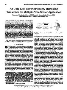
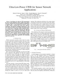
II. PROPOSED I2CSSC DESIGN The architecture of the proposed I2C design is explored in Fig. 1. It is composed of FSM controller (FSMC), input signal sampler (ISS), positive and negative edge detector (PNED), IO control block (IOCB) and interface voltage level circuit (IVLC). Since, now a days CMOS processes for integrated circuits are shrinking and the maximum supply voltages and digital IO logic levels are limited. To interface the I2CSSC lower voltage level to existing different high voltage level master devices, ILVC is added in the design. This simple circuit fulfills the bidirectional level shifting requirements without any directional control signal. It also isolates the I2CSSC power down bus section from the rest of the bus system. The ILVC protects the I2CSSC design against high voltage spikes from the higher voltage side master device [3]. The IOCB is a bi-directional buffer to interface SDA data signal. During read period, sdaCtrl is low and SDA is applied to ISS through input buffer. Similarly, for writing data to IO, sdaCtrl is pulled up to map sdaOut to SDA through output buffer. The ISS samples the incoming SDA data and SCL clock at local clock CLK to make them synchronous with the internal system. The PNED detects the positive and negative edges of both sampled sdaIn and sclIn signals to extract the clock and data information. The FSMC is designed with finite state machine based model according to the protocol for all I2C operations. It implements start, stop, repeat start conditions, acknowledge (ACK) and not acknowledge (NACK) bits, reading, writing and device address verification (DAV) operations. The flow chart of its operation is depicted in Fig. 2 and all conditions (C) are listed in Table I. In this table, the sclD1, sclInd2 and sdaInD1 are delayed versions of the signals sclIn and sdaIn respectively.
Keywords—CMOS, communication, I2C, FSM, level shifter
I. INTRODUCTION With the rapid growth of electronics industry, a variety of methods and protocols for information sharing among numerous electronic components are evolved. There are many standards for communicating between components, circuit boards, and systems. Depending upon the interface signals, these are categorized into parallel and serial interfaces. Similarly, based on data rates, low speed of few Kbps to high speed of upto several Gbps standards are available for a variety of applications. Among all, the inter-integrated circuit (I2C) is one of the famous low data rate serial information transfer protocol [1]. It has become a de facto standard and all well-known system designers and major semiconductor manufacturers support it. It is a standard serial synchronous bi-directional two-wire bus used to interconnect low-speed devices in the communication system. It has different communications modes that ensure the data transfer from 100 kbps upto 5 Mbps [2]. In this paper a a FSM based synchronous design of I2C is explored to make it robust and error free for reliable communication. It is integrated in a pressure sensor analog front end (AFE) for the configuration of its control registers. Since, different master devices may have different voltage levels, so a level shifter design is also integrated with the chip which makes it independent of interface voltage levels [3].discussed. Simulation result for second order CT-SDM is presented in Section IV.
978-1-5386-2285-8/17/$31.00 ©2017 IEEE
Fig. 1. Proposed I2CSSC design
262
ISOCC 2017
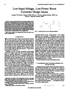
Fig. 3. I2CSSC measurement setup
Fig. 4. I2CSSC Measurement results
byte 0xDD from register address 0x92 of the I2CSSC slave AFE chip. Similarly, the master writes a byte value 0xA6 to the slave register address 0xB3 in Fig. 4(b). The I2CSSC serial communication is also measured at various interface voltage levels of the Master module.
Fig. 2. The FSM controller flow chart C
TABLE 1. THE FSMC CONDITIONS SUMMARY DESCRIPTION DESCRIPTION C
C0 C1 C2 C3 C4
sdaInNe & sclInD1 sclInNe & !sdaInD1 7 bit received sclInNe & RW & DAV sclInNe & !RW & DAV
C5 C6 C7 C8
sclInNe & !DAV 8 bit received sdaInNe & sclInD2 sdaInPe & sclInD2
IV. CONCLUSION This paper explores an ultra low power, FSM based I2C synchronous slave controller which can be interfaced with any IO voltage levels. The direction control signal free bidirectional level shifter circuit isolates slave device and protects it from high voltage level spikes from master side. It requires 157 μW power, draws 87 μA current from 1.8 V supply and occupies 5712 μm² area with 650 gate count. The measurement results proves the functional accuracy and robustness of the proposed design with all I2C operating modes.
III. MEASUREMENT RESULTS The proposed I2CSSC design is integrated in pressure sensor AFE for its register configurations and calibration and it is fabricated with 180 nm CMOS process. The design is translated into hardware with VHDL® language and it needs only 650 gates for its implementation. For synthesis and place and route (P&R) of the presented design, Synopses® Design Compiler® and IC Compiler® tools are utilized and an area of 5712 μm² is reported. In Cadence®, it is integrated with AFE digital block and IVLC. The design needs only 157 μW power while it draws only 87 μA current from 1.8V supply. The measurement setup for testing and verification is captured in Fig. 3. The slave I2CSSC AFE chip is connected to an I2C Master module, which is plugged into PC. A custom GUI is designed for AFE calibration and I2CSSC exhaustive measurement. The SDA and SCL pins are also probed on oscilloscope for visual analysis. The chip internal digital core is operating on 1.8 V which is measured with digital Multimeter. The measurement results for I2CSSC are shown in Fig. 4. In Fig. 4(a), the master device reads a data byte
978-1-5386-2285-8/17/$31.00 ©2017 IEEE
ACKNOWLEDGMENT This material is based upon work supported by the Ministry of Trade, Industry & Energy (MOTIE, Korea) under Industrial Technology Innovation Program. No.10060204, Development of the MEMS technology-based 20bar, 50bar grade air-conditioner pressure sensor element and module with AC 1,800V withstanding voltage characteristic. REFERENCES [1] [2] [3]
263
Zheng-wei HU “I2C Protocol Design for Reusability”, International Symposium on Information Processing, pp. 83-86, Nov. 2010. NXP, “I2C-bus specification and user manual”, ver. 6, Apr. 2014. NXP, ”Level shifting techniques in I2C-bus design”, ver. 1, Jun. 2007.
ISOCC 2017