Arne Øslebø
A diagrammatic notation for modeling access control in tree-based data structures
Thesis for the degree doktor ingeniør Trondheim, May 2008 Norwegian University of Science and Technology Faculty of Information Technology, Mathematics and Electrical Engineering Department of Telematics
NTNU Norwegian University of Science and Technology Thesis for the degree doktor ingeniør Faculty of Information Technology, Mathematics and Electrical Engineering Department of Telematics © Arne Øslebø ISBN 978-82-471-8902-3 (printed version) ISBN 978-82-471-8916-0 (electronic version) ISSN 1503-8181 Doctoral theses at NTNU, 2008:142 Printed by NTNU-trykk
Abstract In modern multi-user computer and network systems, access control is an important aspect of the overall security of a given system. The problem is that as the number of users and systems that are being controlled increases, it can quickly become difficult to keep track of exactly who has access to what. Another problem is that with todays heterogeneous systems, systems of the same type but from different vendors often have different methods for configuring access control. Many systems like SNMP entities, HTTP servers, LDAP, XML based information etc. have one thing in common, they all store their information in a tree based structure. Based on this fact this thesis describe two graphical modeling languages that can be used for specifying the access control setup in most systems that store information in a tree based structure. The Tree-based Access control Modeling Language (TACOMA) is the simplest language that is defined. It is easy to learn and use as it has only 7 symbols and two relations. With this language it is possible to define the exact access control rules for users using a graphical notation. The simplicity of the language do however come at a cost: it is best suited for small or medium sized tasks where the number of users and objects being controlled are limited. To solve the scalability problem a second language is also presented. The Policy Tree-based Access control Modeling Language (PTACOMA) is a policy based version of TACOMA that doubles the number of symbols and relations. While it is harder to learn it scales better to larger tasks. It also allows for distributed specification of access rules where administrators of different domains can be responsible for specifying their own access control rules. Domains can be organized in a hierarchical manner so that administrators on a higher level can create policies that have higher priority and therefor limits what administrators at lower levels can do. The thesis describes the two languages in detail and provides a comparison between them to show the strong and weak points of each language. There is also a detailed case study that shows how the two languages can be used for specifying access control in SNMPv3.
iii
iv
Preface This is my thesis for the degree of doktor ingeniør at the department of Telematics, Norwegian University of Science and Technology (NTNU). The work started in 1997 and is now finally finished. The first four years were done as a research fellow at NTNU and was supported by a joint grant from the Norwegian Research Council, Alcatel, Ericsson, Siemens and Telenor. Since 2001 the work was done in parallel with my work at the Research and Development group in UNINETT. While the work at UNINETT has not been directly related to the work presented in this thesis, I have been able to combine some of the work and use results from UNINETT in a large case study. My supervisor for this research has been Prof. Steinar Andresen and I would like to thank him for his patience and support in finishing this work. I would also like to thank Olav Kvittem at UNINETT for his support and for providing me valuable feedback on earlier versions of the thesis. I would also like to thank my wife and daughters, Noriko, Lisa and Nina, for their patience while I worked on writing the thesis. Without their support I would not have been able to complete it.
v
vi
Contents 1
2
3
4
Introduction 1.1 Background and motivation . . . . . . . . . . . . . . . . . . . . . . 1.1.1 Diagrams . . . . . . . . . . . . . . . . . . . . . . . . . . . 1.1.2 MIB View Modeling Language . . . . . . . . . . . . . . . 1.1.3 A diagrammatic notation for modeling tree-based access control . . . . . . . . . . . . . . . . . . . . . . . . . . . . . . 1.2 Outline of the thesis . . . . . . . . . . . . . . . . . . . . . . . . . . Access Control 2.1 Introduction . . . . . . . . . . . . . . . . . . 2.2 Mandatory Access Control . . . . . . . . . . 2.2.1 Lattice Model . . . . . . . . . . . . . 2.3 Discretionary Access Control . . . . . . . . . 2.3.1 Access Matrix Model . . . . . . . . . 2.4 Role Based Access Control . . . . . . . . . . 2.4.1 Core RBAC . . . . . . . . . . . . . . 2.4.2 Hierarchical RBAC . . . . . . . . . . 2.4.3 Statics Separation of Duty relations . 2.4.4 Dynamic Separation of Duty relations 2.5 Extensible Access Control Markup Language Tree structures 3.1 Tree structure fundamentals . . . 3.1.1 Graphs . . . . . . . . . 3.1.2 Trees . . . . . . . . . . 3.2 Access control in tree structures
. . . .
. . . .
. . . .
. . . .
. . . .
. . . .
Tree-based Access Control Modeling Language 4.1 TACOMA overview . . . . . . . . . . . . . 4.1.1 Editors . . . . . . . . . . . . . . . 4.1.2 TACOMA Parser . . . . . . . . . . 4.1.3 TACOMA ACL optimizer . . . . . 4.1.4 Tree Generator . . . . . . . . . . . 4.1.5 ACL Configurator . . . . . . . . . vii
. . . .
. . . . . .
. . . . . . . . . . .
. . . .
. . . . . .
. . . . . . . . . . .
. . . .
. . . . . .
. . . . . . . . . . .
. . . .
. . . . . .
. . . . . . . . . . .
. . . .
. . . . . .
. . . . . . . . . . .
. . . .
. . . . . .
. . . . . . . . . . .
. . . .
. . . . . .
. . . . . . . . . . .
. . . .
. . . . . .
. . . . . . . . . . .
. . . .
. . . . . .
. . . . . . . . . . .
. . . .
. . . . . .
. . . . . . . . . . .
. . . .
. . . . . .
. . . . . . . . . . .
. . . .
. . . . . .
1 1 1 2 4 4
. . . . . . . . . . .
7 7 8 8 9 9 9 10 11 11 11 11
. . . .
13 13 13 14 16
. . . . . .
19 19 19 22 22 22 22
CONTENTS
viii 4.2
. . . . . . . . . . . . . .
. . . . . . . . . . . . . .
. . . . . . . . . . . . . .
. . . . . . . . . . . . . .
. . . . . . . . . . . . . .
. . . . . . . . . . . . . .
. . . . . . . . . . . . . .
. . . . . . . . . . . . . .
. . . . . . . . . . . . . .
. . . . . . . . . . . . . .
23 23 23 24 39 41 42 43 43 43 43 45 45 46
Policy Tree-based Access control Modeling Language 5.1 Introduction to domains and policies . . . . . . . . 5.1.1 Policy based management . . . . . . . . . 5.1.2 Policy attributes . . . . . . . . . . . . . . . 5.1.3 Policy servers . . . . . . . . . . . . . . . . 5.2 PTACOMA overview . . . . . . . . . . . . . . . . 5.2.1 Policy-based paradigm . . . . . . . . . . . 5.3 Notation . . . . . . . . . . . . . . . . . . . . . . . 5.3.1 Relations . . . . . . . . . . . . . . . . . . 5.3.2 Symbols . . . . . . . . . . . . . . . . . . 5.4 PTACOMA metamodel . . . . . . . . . . . . . . . 5.4.1 Main diagram . . . . . . . . . . . . . . . . 5.4.2 Role definition . . . . . . . . . . . . . . . 5.4.3 Type definition . . . . . . . . . . . . . . . 5.4.4 Policies . . . . . . . . . . . . . . . . . . . 5.4.5 Separation of duty policies . . . . . . . . . 5.4.6 Policy view definitions . . . . . . . . . . . 5.5 Domain hierarchy . . . . . . . . . . . . . . . . . . 5.6 Policy conflicts . . . . . . . . . . . . . . . . . . . 5.7 Distributed management . . . . . . . . . . . . . . 5.8 PTACOMA XML format . . . . . . . . . . . . . .
. . . . . . . . . . . . . . . . . . . .
. . . . . . . . . . . . . . . . . . . .
. . . . . . . . . . . . . . . . . . . .
. . . . . . . . . . . . . . . . . . . .
. . . . . . . . . . . . . . . . . . . .
. . . . . . . . . . . . . . . . . . . .
. . . . . . . . . . . . . . . . . . . .
. . . . . . . . . . . . . . . . . . . .
. . . . . . . . . . . . . . . . . . . .
51 51 51 52 53 53 54 54 56 57 63 64 64 66 69 69 69 71 71 73 74
. . . . . .
91 91 91 92 92 92 97
4.3 4.4 4.5 4.6 4.7 4.8
4.9 5
6
Notation . . . . . . . . . . . . . . . . . . . . . . 4.2.1 Diagrams . . . . . . . . . . . . . . . . . 4.2.2 Relations . . . . . . . . . . . . . . . . . 4.2.3 Symbols . . . . . . . . . . . . . . . . . EOID functions . . . . . . . . . . . . . . . . . . Hierarchy . . . . . . . . . . . . . . . . . . . . . User administration . . . . . . . . . . . . . . . . RBAC support . . . . . . . . . . . . . . . . . . . XACML support . . . . . . . . . . . . . . . . . Formal specification . . . . . . . . . . . . . . . . 4.8.1 Meta model . . . . . . . . . . . . . . . . 4.8.2 XML Schema . . . . . . . . . . . . . . . 4.8.3 Shortcomings of the formal specification TACOMA XML format . . . . . . . . . . . . . .
TACOMA and PTACOMA comparison 6.1 Complexity . . . . . . . . . . . . . . . . 6.2 Scalability . . . . . . . . . . . . . . . . . 6.3 Maintainability . . . . . . . . . . . . . . 6.4 Distributed specification of access control 6.5 Example . . . . . . . . . . . . . . . . . . 6.6 Summary . . . . . . . . . . . . . . . . .
. . . . . .
. . . . . .
. . . . . .
. . . . . .
. . . . . .
. . . . . .
. . . . . .
. . . . . .
. . . . . .
. . . . . .
. . . . . .
. . . . . .
. . . . . .
CONTENTS
ix
7
Case study: Using PTACOMA to Model Access Control in a Large Scale Deployment of Passive Monitoring Probes 99 7.1 Monitoring API . . . . . . . . . . . . . . . . . . . . . . . . . . . . 99 7.1.1 Distributed MAPI . . . . . . . . . . . . . . . . . . . . . . . 101 7.1.2 MAPI security mechanisms . . . . . . . . . . . . . . . . . 101 7.1.3 SNMP access . . . . . . . . . . . . . . . . . . . . . . . . . 101 7.2 Management information . . . . . . . . . . . . . . . . . . . . . . . 103 7.2.1 Interface . . . . . . . . . . . . . . . . . . . . . . . . . . . 103 7.2.2 Organization . . . . . . . . . . . . . . . . . . . . . . . . . 104 7.2.3 User . . . . . . . . . . . . . . . . . . . . . . . . . . . . . . 104 7.2.4 Flow . . . . . . . . . . . . . . . . . . . . . . . . . . . . . 104 7.2.5 Function . . . . . . . . . . . . . . . . . . . . . . . . . . . 105 7.2.6 Argument . . . . . . . . . . . . . . . . . . . . . . . . . . . 105 7.3 Using the MAPI MIB . . . . . . . . . . . . . . . . . . . . . . . . . 106 7.4 Access control requirements . . . . . . . . . . . . . . . . . . . . . 106 7.5 SNMPv3 USM and VACM configuration . . . . . . . . . . . . . . 107 7.5.1 UNINETT administrator . . . . . . . . . . . . . . . . . . . 107 7.5.2 Guest users . . . . . . . . . . . . . . . . . . . . . . . . . . 107 7.5.3 Customer administrators . . . . . . . . . . . . . . . . . . . 108 7.5.4 Full configuration . . . . . . . . . . . . . . . . . . . . . . . 108 7.6 PTACOMA diagrams . . . . . . . . . . . . . . . . . . . . . . . . . 108 7.6.1 UNINETT administrators . . . . . . . . . . . . . . . . . . 108 7.6.2 Guest users . . . . . . . . . . . . . . . . . . . . . . . . . . 109 7.6.3 Customer administrators . . . . . . . . . . . . . . . . . . . 109 7.7 Summary and conclusions . . . . . . . . . . . . . . . . . . . . . . 111
8
Conclusions and further work 113 8.1 Conclusions . . . . . . . . . . . . . . . . . . . . . . . . . . . . . . 113 8.2 Related work . . . . . . . . . . . . . . . . . . . . . . . . . . . . . 114 8.3 Further work . . . . . . . . . . . . . . . . . . . . . . . . . . . . . 114
A Lis of Acronyms B Simple Network Management Protocol B.1 History . . . . . . . . . . . . . . . . . . . . B.2 Framework . . . . . . . . . . . . . . . . . . B.2.1 Management Information Base . . . . B.2.2 Structure of Management Information B.3 SNMPv3 reference model . . . . . . . . . . . B.4 User-based Security Model . . . . . . . . . . B.4.1 usmUserTable . . . . . . . . . . . . B.4.2 Adding users . . . . . . . . . . . . . B.4.3 Deleting users . . . . . . . . . . . . . B.4.4 Changing keys . . . . . . . . . . . .
117
. . . . . . . . . .
. . . . . . . . . .
. . . . . . . . . .
. . . . . . . . . .
. . . . . . . . . .
. . . . . . . . . .
. . . . . . . . . .
. . . . . . . . . .
. . . . . . . . . .
. . . . . . . . . .
. . . . . . . . . .
. . . . . . . . . .
119 119 120 120 120 121 122 122 124 125 125
CONTENTS
x B.5 View-based Access Control Model . B.5.1 vacmSecurityToGroupTable B.5.2 vacmAccessTable . . . . . . B.5.3 vacmViewTreeFamilyTable B.5.4 Creating MIB views . . . .
. . . . .
. . . . .
. . . . .
. . . . .
. . . . .
. . . . .
. . . . .
. . . . .
. . . . .
. . . . .
. . . . .
. . . . .
. . . . .
. . . . .
. . . . .
. . . . .
. . . . .
125 126 126 128 128
C Prototype implementation of TACOMA and PTACOMA for configuring SNMPv3 access control 131 C.1 Introduction . . . . . . . . . . . . . . . . . . . . . . . . . . . . . . 131 C.1.1 DOM and SAX . . . . . . . . . . . . . . . . . . . . . . . . 132 C.2 TACOMA Parser . . . . . . . . . . . . . . . . . . . . . . . . . . . 132 C.2.1 getAccessRules . . . . . . . . . . . . . . . . . . . . . . . . 133 C.3 Configuring SNMP access control . . . . . . . . . . . . . . . . . . 134 C.4 Limitations . . . . . . . . . . . . . . . . . . . . . . . . . . . . . . 134 C.5 PTACOMA implementation . . . . . . . . . . . . . . . . . . . . . 134 C.6 Conclusions . . . . . . . . . . . . . . . . . . . . . . . . . . . . . . 137 D TACOMA XML Schema
139
E PTACOMA XML Schema
145
F MAPI MIB
169
Bibliography
179
List of Figures 2.1 2.2 2.3
Access control . . . . . . . . . . . . . . . . . . . . . . . . . . . . . Role hierarchy . . . . . . . . . . . . . . . . . . . . . . . . . . . . . XACML core framework . . . . . . . . . . . . . . . . . . . . . . .
7 11 12
3.1 3.2 3.3 3.4 3.5
Directed and undirected graphs Free tree . . . . . . . . . . . . Forest . . . . . . . . . . . . . Rooted tree . . . . . . . . . . Access control . . . . . . . . .
. . . . .
. . . . .
. . . . .
. . . . .
. . . . .
. . . . .
. . . . .
. . . . .
. . . . .
. . . . .
. . . . .
. . . . .
. . . . .
. . . . .
. . . . .
13 15 15 15 17
4.1 4.2 4.3 4.4 4.5 4.6 4.7 4.8 4.9 4.10 4.11 4.12 4.13 4.14 4.15 4.16 4.17 4.18 4.19 4.20 4.21 4.22
TACOMA framework . . . . . . . . . . . TACOMA diagram . . . . . . . . . . . . Tree structure . . . . . . . . . . . . . . . TACOMA symbols and relations . . . . . TACOMA user . . . . . . . . . . . . . . Illegal TACOMA user symbol example . Legal TACOMA user symbol example . . TACOMA entity . . . . . . . . . . . . . Exclude TACOMA entity . . . . . . . . . Global TACOMA entity . . . . . . . . . TACOMA children symbol . . . . . . . . TACOMA subtree symbol . . . . . . . . Table tree structure . . . . . . . . . . . . TACOMA table row symbol . . . . . . . TACOMA group symbol . . . . . . . . . TACOMA group contents . . . . . . . . . TACOMA group expanded . . . . . . . . TACOMA hierarchy conflicts . . . . . . . TACOMA Meta Model . . . . . . . . . . TACOMA dependency loop . . . . . . . TACOMA diagram without entity symbol TACOMA XML structure . . . . . . . . .
. . . . . . . . . . . . . . . . . . . . . .
. . . . . . . . . . . . . . . . . . . . . .
. . . . . . . . . . . . . . . . . . . . . .
. . . . . . . . . . . . . . . . . . . . . .
. . . . . . . . . . . . . . . . . . . . . .
. . . . . . . . . . . . . . . . . . . . . .
. . . . . . . . . . . . . . . . . . . . . .
. . . . . . . . . . . . . . . . . . . . . .
. . . . . . . . . . . . . . . . . . . . . .
. . . . . . . . . . . . . . . . . . . . . .
. . . . . . . . . . . . . . . . . . . . . .
. . . . . . . . . . . . . . . . . . . . . .
. . . . . . . . . . . . . . . . . . . . . .
. . . . . . . . . . . . . . . . . . . . . .
20 21 21 23 24 25 26 28 29 30 33 34 35 36 38 39 40 42 44 45 46 49
5.1 5.2
Policy server . . . . . . . . . . . . . . . . . . . . . . . . . . . . . PTACOMA components . . . . . . . . . . . . . . . . . . . . . . .
53 55
. . . . .
xi
. . . . .
. . . . .
. . . . .
. . . . .
LIST OF FIGURES
xii 5.3 5.4 5.5 5.6 5.7 5.8 5.9 5.10 5.11 5.12 5.13 5.14 5.15 5.16 5.17 5.18 5.19 5.20 5.21 5.22 5.23 5.24 5.25 5.26 5.27 5.28 5.29 5.30
PTACOMA diagram . . . . . . . . . . . . . . . . . . . PTACOMA symbols . . . . . . . . . . . . . . . . . . . PTACOMA subject relation . . . . . . . . . . . . . . . . PTACOMA role example . . . . . . . . . . . . . . . . . PTACOMA role example - domain contents . . . . . . . PTACOMA domain arithmetic example - group contents PTACOMA domain arithmetic example . . . . . . . . . PTACOMA alternative domain arithmetic syntax . . . . PTACOMA role definitions . . . . . . . . . . . . . . . . PTACOMA type example . . . . . . . . . . . . . . . . . PTACOMA type example - domain contents . . . . . . . PTACOMA separation of duty policy examples . . . . . PTACOMA policy view example . . . . . . . . . . . . . PTACOMA policy view example - domain contents . . . PTACOMA XML structure . . . . . . . . . . . . . . . . Main diagram metamodel . . . . . . . . . . . . . . . . . Role definition metamodel . . . . . . . . . . . . . . . . Users and domains metamodel . . . . . . . . . . . . . . Domain modeling metamodel . . . . . . . . . . . . . . . Type definition metamodel . . . . . . . . . . . . . . . . Entities and domains metamodel . . . . . . . . . . . . . Policy metamodel . . . . . . . . . . . . . . . . . . . . . Policy subject metamodel . . . . . . . . . . . . . . . . . Constraint metamodel . . . . . . . . . . . . . . . . . . . Policy target metamodel . . . . . . . . . . . . . . . . . PTACOMA separation of duty policies metamodel . . . Policy view definitions metamodel . . . . . . . . . . . . PolicyView group of entities metamodel . . . . . . . . .
. . . . . . . . . . . . . . . . . . . . . . . . . . . .
. . . . . . . . . . . . . . . . . . . . . . . . . . . .
. . . . . . . . . . . . . . . . . . . . . . . . . . . .
. . . . . . . . . . . . . . . . . . . . . . . . . . . .
. . . . . . . . . . . . . . . . . . . . . . . . . . . .
. . . . . . . . . . . . . . . . . . . . . . . . . . . .
56 56 57 65 65 66 67 67 68 70 70 71 72 72 77 78 79 80 81 82 83 84 85 86 87 88 89 90
6.1 6.2 6.3 6.4 6.5 6.6 6.7 6.8 6.9
Initial department A TACOMA diagram . . Initial department B TACOMA diagram . . Modified department A TACOMA diagram TACOMA diagram of GroupA . . . . . . . Modified department B TACOMA diagram Initial department A PTACOMA diagram . Initial department B PTACOMA diagram. . Modified department A PTACOMA diagram Blocking users from department B . . . . .
. . . . . . . . .
. . . . . . . . .
. . . . . . . . .
. . . . . . . . .
. . . . . . . . .
. . . . . . . . .
93 93 94 94 95 95 96 96 97
7.1 7.2 7.3 7.4 7.5
PTACOMA diagram for UNINETT administrators . . . . . . . . PTACOMA diagram for guest users . . . . . . . . . . . . . . . . MAPI access group contents . . . . . . . . . . . . . . . . . . . . PTACOMA diagram for local access for customer administrators. PTACOMA diagram for remote access for customer administrators
. . . . .
109 110 110 111 112
. . . . . . . . .
. . . . . . . . .
. . . . . . . . .
. . . . . . . . .
. . . . . . . . .
. . . . . . . . .
. . . . . . . . .
LIST OF FIGURES
xiii
8.1
XACML constraints in PTACOMA . . . . . . . . . . . . . . . . . . 115
B.1 B.2 B.3 B.4 B.5
SNMP framework . . . . . . . SNMPv3 reference model . . . USM MIB structure . . . . . . VACM MIB structure . . . . . VACM access control process
. . . . .
. . . . .
. . . . .
. . . . .
. . . . .
. . . . .
. . . . .
. . . . .
. . . . .
. . . . .
. . . . .
. . . . .
. . . . .
. . . . .
. . . . .
. . . . .
. . . . .
. . . . .
. . . . .
. . . . .
120 121 123 127 128
C.1 C.2 C.3 C.4
TACOMA Parser design Domain D1 . . . . . . . Domain D2 . . . . . . . ifTable policy . . . . . .
. . . .
. . . .
. . . .
. . . .
. . . .
. . . .
. . . .
. . . .
. . . .
. . . .
. . . .
. . . .
. . . .
. . . .
. . . .
. . . .
. . . .
. . . .
. . . .
. . . .
133 135 135 136
. . . .
. . . .
. . . .
xiv
LIST OF FIGURES
List of Tables 2.1
Access matrix . . . . . . . . . . . . . . . . . . . . . . . . . . . . .
9
4.1
Table example . . . . . . . . . . . . . . . . . . . . . . . . . . . . .
35
6.1
TACOMA and PTACOMA weak and strong points . . . . . . . . .
97
7.1 7.2
MAPI MIB access control for customer administrators . . . . . . . 107 MAPI MIB access control for guest users . . . . . . . . . . . . . . 107
B.1 Object identifiers for mibA . . . . . . . . . . . . . . . . . . . . . . 129 B.2 vacmViewTreeFamilyTable entries . . . . . . . . . . . . . . . . . . 129
xv
xvi
LIST OF TABLES
Chapter 1 Introduction This chapter describes the background and motivation behind the thesis and provides an overview of how the rest of the thesis is organized.
1.1 Background and motivation “A picture is worth a thousand words”. This is a maxim well known to most people, although it is often mistakenly quoted as being a Chinese proverb belonging to Confucius. Its origin is actually two articles published in the trade journal “Printer’s Ink” in 1921 and 1927 by Frederick Barnard[1, 2]. The first article was titled “One Look Is Worth a Thousand Words” and talked in general about the benefits of advertising with pictures on street cars. In this article the proverb was attributed to a “famous Japanese philosopher”. In 1927 he revised the saying to “One picture is worth ten thousand words” and this time he claimed it was a “Chinese proverb”. By calling it a Chinese proverb Frederick Bernard thought his words would be more believable. Today the proverb is known all over the world and few question its validity. In computer science and telecommunication pictures, diagrams and graphical notations have been used for a long time to help programmers and system operators to understand the complexities of modern computer and communication systems.
1.1.1 Diagrams The most common visualization method used in computer science and telecommunication is diagrams. They are used as a way to understand the complex architecture of modern systems. A diagram is a method for conveying a message by means of drawing lines. The Merriam-Webster dictionary[3] defines a diagram as: “a graphic design that explains rather than represents; especially : a drawing that shows arrangement and relations (as of parts)”. The earliest forms of diagrams are maps. Maps are considered diagrams because they relate physical distance between locations in the world and physical distance 1
2
CHAPTER 1. INTRODUCTION
of these locations on paper. At the same time they abstract out details, for example roads are represented by straight lines, coastlines are abbreviated etc. It is this abstraction of details that make diagrams very useful for dealing with complex computer and communication systems. In computer science and telecommunication there are many examples of highly successful graphical notations. One well known notation is Entity-Relationship diagrams. These diagrams are used for high level modeling of complex database systems and help designers create accurate and useful conceptual models. The E-R diagram was created by Professor Peter Chen[4] to serve as a tool for communication between designers and users. Chen recognized that users and developers often have difficulties communicating and that a visual diagrammatic notation could help bridge this gap. An E-R diagram presents a visual overview of the data and relationships between data in a database in a way that is relatively easy to understand even for normal users. Another example of a diagrammatic language is the Specification and Description Language (SDL)[5]. The development of this language started in 1972 and it was designed as a language for specifying and designing telecommunication systems. Today the language can be used to develop any real time concurrent system. The purpose of SDL is to help developers understand and model the complex behavior of real time concurrent systems and protocols. For development of large and complex object oriented software systems, the Unified Modeling Language (UML)[6] is commonly used. UML is a collection of several diagram types that makes it possible for developers to model both the static and dynamic properties of large and complex software projects. These are just a few examples of the many graphical notations that successfully have made complex matters easier to handle.
1.1.2 MIB View Modeling Language Based on the fact that visual representation using diagrams helps people to better understand complex systems, the work described in this thesis started out as research into finding an easy method for specifying access control configurations in the Simple Network Management Protocol (SNMP). SNMP was released as a draft standard in 1988 and became a full standard in 1990[7, 8, 9]. Since its release, SNMP has been the most commonly used protocol for monitoring network equipment in TCP/IP networks like the Internet and big intranets. Today, not only network devices like routers and switches support SNMP, but also most other devices that are connected to a network like printers and servers have built in support for it. One weakness with the first and second version of SNMP is that they both share a very weak security model where the only authentication is a password sent in clear text over the network. This lack of security is one of the reasons why SNMP is most commonly used for monitoring and only rarely used for configuring devices. When the work on this thesis started, the draft version of SNMPv3[10, 11, 12, 13, 14, 15, 16, 17, 18] had just been released. SNMPv3 supports proper security mech-
1.1. BACKGROUND AND MOTIVATION
3
anisms like strong authentication and access control. Many organizations and companies had complained about the weak security in SNMP and at that time many expected that SNMPv3 would increase the usage of SNMP for configuration as it could now be done in a secure way. In one of the first published books about SNMPv3[19] the author wrote in the preface: “I have this image in my mind of SNMPv3 as a series of dark clouds that are rolling in over the horizon. Like it or not the storm is coming and you’d better be prepared for it” So far this storm has not come, one reason being that operators do not want yet another system of user authentication to keep track of. The IETF has now started a working group called Integrated Security Model for SNMP (ISMS)[20], which works on extending SNMPv3 so that it can use external authentication systems like TACACS1 or RADIUS2 . The access control mechanism defined in SNMPv3 is the View-based Access Control Model (VACM). One of the goals when developing this model was that it should add as little overhead as possible when processing SNMP packets and an implementation should have a small footprint. The reason for these design goals was that SNMP is often implemented on network equipment with limited resources. One cost of the low overhead and small implementation footprint of VACM, is that it does not scale well for a large number of different users and fine grained access control. The access control mechanisms in VACM are controlled through a MIB called the VACM MIB. The VACM MIB contains four tables that together decides if a user is allowed access to a managed object or not and what type of access he is granted. When these tables grow large, it can quickly become difficult to keep track of exactly who have access to what. There are commercial tools available that implements a graphical interface to the VACM tables. This is however not enough since the managers controlling the access rights still have to manipulate the tables directly without any abstractions. This was the motivation behind this thesis. It started out as a work on defining a graphical modeling language that could be used for configuring the access control and security parameters in SNMPv3. This research first resulted in the MIB View Modeling Language (MVML)[21]. MVML is a simple graphical notation with few symbols and relations specially designed for specifying MIB views for VACM. This language was found to be very easy to learn and use for small and medium sized networks. To handle large networks with a high number of users and managed objects, the Policy-based MIB View Modeling Language (PMVML) was created. PMVML uses a policy based paradigm for specifying access control. The cost for being able to scale to large networks is an increase in complexity. PMVML doubled the number of available symbols and relations. 1
Terminal Access Controller Access Control System Authentication Dial-In User Service
2 Remote
4
CHAPTER 1. INTRODUCTION
1.1.3 A diagrammatic notation for modeling tree-based access control As the work on implementing a prototype for MVML and PMVML progressed, it became apparent that the methods used could easily be made more generic and be applied to almost any application that store information in a tree-based structure. Some examples are SNMP, LDAP or even web pages on a HTTP server that stores the files in a tree-based file system. The work presented in this thesis is therefore two general purpose graphical modeling languages for specifying access control for applications and systems that stores information in a tree based structure. The two languages presented are: Tree-based Access control Modeling Language (TACOMA) a simple notation with few symbols and relations. It was developed with ease of use as the primary goal. It is however best suited for small and medium sized tasks with a limited number of users and objects. Policy Tree-based Access control Modeling Language (PTACOMA)[22] a more advanced notation which builds on TACOMA and doubles the number of symbols and relations. It can be used for large tasks with a high number of users and objects at the cost of being more difficult to learn and use. It is based on policies and together with a proper editor it allows for distributed specification of access control that can span multiple administrative domains. Configuring access control in applications and systems can often be challenging. First of all each type of application or system usually have very different methods for doing the configuration and each method must be learned properly so that access to protected resources are not granted by mistake. Even systems of the same type but from different vendors can often have different methods for configuring the access control. Instead of having to learn and master all these different methods for configuring access control, the graphical modeling languages described in this thesis can be used. Depending on the number of users and resources being controlled, administrators only have to learn one or two graphical modeling languages for configuring all applications and devices that stores information in tree based structures.
1.2 Outline of the thesis The thesis consists of 8 chapters where the main work is described in chapter 4 through 7. Chapter 2 gives a short introduction to various access control models. Chapter 3 introduces the mathematical properties of trees and discusses access control in tree based structures.
1.2. OUTLINE OF THE THESIS
5
Chapter 4 presents the Tree-based Access Control Modeling Language. The syntax of the modeling language is described in detail and all symbols defined in the language are described. This chapter also describes an XML format that can be used for storing TACOMA diagrams and which also act as a formal definition of the structure of the language. Chapter 5 describes the policy based version of TACOMA called PTACOMA. It starts by giving a short introduction to domains and policies and then follows the same outline as chapter 4 where it provides a detailed description of all available symbols. An XML format is also described and some simple examples on how the language can be used are given. Chapter 6 compares the two languages defined in the thesis and discusses the strengths and weaknesses of each language. The chapter also provides a rationale for why both languages are useful. Chapter 7 is a case study which shows how PTACOMA can be applied for specifying access control in SNMPv3 for a real world use case. Chapter 8 summarizes the work presented in the thesis, provides some conclusions and discusses further work. Appendix B is an overview of SNMP with focus on the security mechanisms of SNMPv3. Appendix C describes a prototype implementation of TACOMA and PTACOMA for configuring access control in SNMP entities.
6
CHAPTER 1. INTRODUCTION
Chapter 2 Access Control This chapter provides a short introduction to access control and gives an overview of various existing access control models.
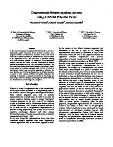
2.1 Introduction The task of access control in a system is to limit what authenticated users are allowed to access in the system. Figure 2.1 shows a high level abstraction of how access control works. A user, usually called subject, who wants to access a resource, usually called object, in the system is first authenticated by the authentication system. The task of the authentication system is to verify the identity of subjects trying to access the system. Subjects do not have to be real users, but can also be applications running on behalf of a user. If the subject is properly identified, then the request is passed on to the access control system. The access control system checks with an authorization database to see if the user is allowed to access the object. There can be different types of access, like read, write, create etc., and each subject can have limited or no access to objects based on the type of access. To control which subject has access to which objects, a security administrator can update the authorization database.
Figure 2.1: Access control 7
8
CHAPTER 2. ACCESS CONTROL
The authorization database is rarely implemented as a centralized database, but instead it is often distributed where for example each object has a list of attributes deciding who can access it. It is also important to realize that in many systems, subjects can themselves be objects and be controlled by the access control system. Research into access control models has been going on for many years. The U.S. Department of Defense (DoD) was among the first to formalize access control models. This work was part of the Trusted Computer System Evaluation Criteria (TCSEC)[23]. In this document two different access control models are defined: Discretionary Access Control(DAC) and Mandatory Access Control (MAC). It has later been shown that these two models do not always fulfill the needs of organizations outside the DoD and a lot of research have gone into defining a new access control model called Role-Based Access Control (RBAC)[24, 25, 26, 27, 28]. In 2004 RBAC was standardized by the InterNational Committee for Information Technology Standards (INCITS).
2.2 Mandatory Access Control Mandatory Access Control (MAC) was first specified by TCSEC and is heavily based on military requirements. MAC is a model that limits access to objects based on the sensitivity of the information contained in the object. The level of sensitivity is represented by a label. The sensitivity levels are hierarchical in nature and can typically be top secret, secret, confidential or unclassified. Subjects are assigned a security clearance and access to objects are granted or denied depending on the relation between clearance of the subject and the security label of the object.
2.2.1 Lattice Model A formal model of the MAC model using lattices was developed by Denning[29]. In this model there is a set of subjects S , objects O and security levels L . All subjects and objects are then assigned a specific security level. To decide if a subject s ∈ S can access an object o ∈ O the model looks at the relationship between the security level, clearance, of the subject and the security level, classification, of the object. Access is permitted if the clearance dominates the classification, otherwise it is denied. The work by Denning defines a relation ≥ which can be used to compare two security levels to decide if access is granted or denied. Assume that objects can have different sensitivity levels like top secret (TS), secret (S), confidential (C) or unclassified (U) which has a natural ordering so that T S > S > C > U . The collection of object sensitivity is then R = {T S, S,C,U }. For any user that needs to access objects there will be a collection of necessary objects called compartments. Let this collection of compartments be T . We then have L = R × T and a security level l ∈ L is a pair (lR , lT ) where lR ∈ R and lT ∈ T . The relation ≥ can then be defined as:
2.3. DISCRETIONARY ACCESS CONTROL
s1 s2 s3
o1 read,write read execute
o2 read
o3 read
read
9 o4 read, write read read, execute
Table 2.1: Access matrix ′ ) and (l ⊇ l ′ ) for l, l ′ ∈ L . (l ≥ l ′ ) ⇔ (lR ≥ lR T T With this relation a subject s ∈ S with clearance ls ∈ L is given access to an object O with classification lo ∈ L if and only if ls ≥ lo .
2.3 Discretionary Access Control Discretionary Access Control (DAC) is the second access control model that was specified in TCSEC. In DAC the owner of an object controls the access control permissions of it and it is up to the owner’s discretion to assign access permission to objects. DAC is a model often found in commercial systems, one example being UNIX file systems.
2.3.1 Access Matrix Model Most systems that supports DAC uses an access matrix model which was first introduced by Lampson[30]. This model uses a matrix where the rows are indexed by the subjects S and the columns by the objects O. All access permissions held by a user s ∈ S over an object o ∈ O is specified in the matrix entry (s, o). Table 2.1 shows an example of an access matrix. In this table we can for example see that the entry (s2 , o4 ) gives user s2 read access to object o4 . In real world systems the access matrix will contain a lot of empty entries and can be very large. For this reason DAC is rarely implemented as a real matrix. The table is usually stored either by column or by row. Storing by columns means that each object has an Access Control List(ACL) associated with it and this list contains the access rights of each subject that are allowed access to the object. For example object o2 would have an ACL like this: (s1 , read), (s4, read). Storing by row means that each subject has a list of capabilities that shows which objects the subject can access and the type of access that is allowed. Subject s3 has the following capabilities: (o1 , execute), (o2, read), (o4, read execute).
2.4 Role Based Access Control While many commercial systems have implemented DAC, many systems have also implemented some sort of role based access control for many years[31]. The basic
CHAPTER 2. ACCESS CONTROL
10
principal behind Role-Based Access Control(RBAC)[32] is that instead of giving access rights directly to subjects, they are given to roles and then subjects are assigned one or more roles to allow accessing objects. RBAC is an advanced concept and requirements varies a lot among different systems. Because of this the RBAC standard is divided into four parts where only one of them is mandatory to support. The rest are optional and can be added if needed. The four parts are: Core RBAC the essential aspects of RBAC that all systems must support. Hierarchical RBAC adds support for hierarchical roles. SSD
Static Separation of Duty relations.
DSD
Dynamic Separation of Duty relations.
2.4.1 Core RBAC The Core RBAC model specifies element sets and relations that are mandatory for all systems that supports RBAC. The five basic data elements are: USERS
a set of users that are allowed access to the system
ROLES
a set of roles that can be assigned to users
OBS
a set of objects that can be accessed by roles
OPS
a set of operations that can be performed on objects
PRMS
a set of permissions that allows specific operations to be applied to specific objects
In addition to these five basic data elements, there is also a set called SESSIONS. A session is a mapping between a user and one or more roles that are assigned to the user. This means that a user can have different roles depending on the current session. One important aspect of RBAC is that permissions to access objects are always given to roles and never directly to a user. If one single user needs more access, a new role should be created and given access and the user should be assigned this new role. A use can have multiple roles.
2.5. EXTENSIBLE ACCESS CONTROL MARKUP LANGUAGE
11
Figure 2.2: Role hierarchy
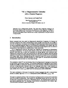
2.4.2 Hierarchical RBAC Hierarchical RBAC makes it possible to create a hierarchy of roles where one role can inherit access rules from other roles. Figure 2.2 shows an example of this. In this figure we can see that role R1 inherits R0 and role R3 inherits both R1 and R2 . The fact that a role rx inherits role ry means that all privileges of ry is also privileges of rx [33]. While hierarchical RBAC is optional, it is a feature that is commonly used by products offering role based access control.
2.4.3 Statics Separation of Duty relations Separation of duty is an important feature in many systems. The idea is that for critical tasks it should not be possible for one single person to have access to do everything and that the task has to be separated between two or more people. With static separation of duty (SSD) there are rules that dictates which roles a user might be assigned. As an example a rule might dictate that a user that has been assigned role r0 can not also be assigned role r1 .
2.4.4 Dynamic Separation of Duty relations With dynamic separation of duty (DSD) the rules dictating which roles a user can have, can be dynamic and change according to which session the user uses. For example if a user is assigned role r0 , a DSD rule can say that the user can only take on role r1 if he deactivates role r0 .
2.5 Extensible Access Control Markup Language The Extensible Access Control Markup Language (XACML)[34, 35] is an XML based language standardized by Organization for the Advancement of Structured Information Standards (OASIS) for specifying access control requirements. It is a
12
CHAPTER 2. ACCESS CONTROL
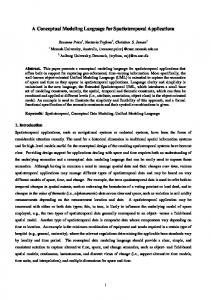
Figure 2.3: XACML core framework general purpose language designed for supporting the needs of most authorization systems. The standard documents describing XACML defines both the syntax for the policy language as well as a request and response format for querying policy systems. The core framework for XACML is shown in figure 2.3. This figure shows the 6 usual steps in XACML for deciding if an action is permitted or not: 1. Access request: the access requester, for example an application, sends an access request to the policy enforcement point. 2. XACML request: the policy enforcement point (PEP) sends an XACML request message to the policy decision point (PDP). The format of this message is specified by XACML. 3. Fetch policy: the PDP will look at the XACML Request, identify the targeted resources of the request and fetch all policies that governs these resources. 4. Fetch optional attributes: a policy specified in XACML can include attributes and conditions that these attributes have to fulfill for the policy to be valid. This can for example be used for creating a policy saying that a user only has access as long as the load on the system is low. 5. XACML response: response back to the PEP can be: permit, deny, not applicable or indeterminate. 6. Access resource: if PEP receives back a permit response, access to the resource is carried out.
Chapter 3 Tree structures This chapter provides an overview of the mathematical properties of trees. To be able to understand these properties better, the chapter starts by giving a general overview of graphs. The chapter ends by describing access control mechanisms in tree-based structures.
3.1 Tree structure fundamentals Storing information in a tree structure is a method much used in computer science. Trees are a special form of graphs so to understand the mathematical properties of trees, one must first understand the basics of graphs.
3.1.1 Graphs There are two main types of graphs, directed and undirected. Figure 3.1 shows an example of these two types of graphs where graph (a) is directed and (b) is undirected. This figure is used to define the various aspects and terminology for graphs. The overview of graphs in this section is not complete and only enough basic properties are given to be able to understand the description of trees given later in the chapter.
1
2
3
(a) 1
2
3
(b) Figure 3.1: Directed and undirected graphs 13
CHAPTER 3. TREE STRUCTURES
14
The circles in figure 3.1 are called vertices and the lines between them are edges. In a directional graph, the edges are drawn using an arrow while undirectional graphs use a simple line. The common mathematical notation of a graph G is G = (V, E) where V is a finite set of vertices and E is a binary relation on V specifying edges. With this notation the graph (a) in the figure can be written as: G = ({1, 2, 3}, {(1, 2), (2, 2), (3, 2)}. The only difference between a directed and an undirected graph, is that in an undirected graph the edge set E consists of unordered pairs of vertices. A single edge of a graph is a set {u, v} where u, v ∈ V . For undirected graphs u 6= v also applies. The set {u, v} is commonly written using the notation (u, v). A path in a graph G = (V, E) from a vertex u to a vertex u′ is a sequence of vertices,< v0 , v1 , ...., vk >, where u = v0 , u′ = vk and (vi−1, vi ) ∈ E for i = 1, 2, ...k. The number of edges in the path is considered the length of the path. If all vertices in a path are distinct, the path is called simple. In a simple graph, the path < v0 , v1 , ..., vk > forms a cycle if v0 = vk and the path contains at least one edge. An acyclic graph is a graph that contains no cycles. An undirected graph is connected if every pair of vertices is connected by a path.
3.1.2 Trees There are different types of trees. A free tree as shown in figure 3.2 is a connected, acyclic, undirected graph. If an undirected graph is acyclic but disconnected, it is a forest as shown in figure 3.3. If G = (V, E) is an undirected graph, the following properties for a free tree is true[36]: 1. G is a free tree 2. Any two vertices in G are connected by a unique simple path. 3. G is connected, but if any edge is removed from E, the resulting graph is disconnected. 4. G is connected, and |E| = |V | − 1 5. G is acyclic, and |E| = |V | − 1 6. G is acyclic, but if any edge is added to E, the resulting graph contains a cycle. Figure 3.4 shows a rooted tree. In a rooted tree one of the vertices is distinguished from the others and is called the root of the tree. A vertex in a rooted tree is often referred to as a node. In figure 3.4 node 1 is the root of the tree. In a rooted tree T with root r, any node y on the direct path from r to x is an ancestor of x. If y is an ancestor of x, then x is a descendant of y. In figure 3.4 node 9 is a descendant of node 2 and node 4 is an ancestor of both node 7 and 8.
3.1. TREE STRUCTURE FUNDAMENTALS
15
Figure 3.2: Free tree
Figure 3.3: Forest
1
2
5
depth 0
4
3
6
7
depth 1
8
9
depth 2
depth 3
Figure 3.4: Rooted tree
16
CHAPTER 3. TREE STRUCTURES
By definition all nodes are both an ancestor and a descendant of itself. If x 6= y and y is an ancestor of x, then y is a proper ancestor of x and x is a proper descendant of y. A subtree rooted at a node x is the tree rooted at x containing the descendants of x. In figure 3.4 the subtree rooted at node 2 will include node 2, 5, 6 and 9. On the path from root r of a tree T , to a node x, the last edge on the path is (y, x). Here y is the parent of x and x is a child of y. When two or more nodes have the same parent, they are siblings. The only node in T that does not have any parent is the root node r. A node with no descendants is called a leaf. The degree of a node x in a rooted tree T is the number of descendants that node x have. The length of the path from the root r to a node x is called the depth of x in T . In figure 3.4 node 6 have a depth of 2.
3.2 Access control in tree structures Many applications that store information in tree based structures need access control to be able to restrict access to certain nodes or subtrees in the main tree structure. This thesis will use a notation for specifying access control where access rules are used to either include or exclude nodes or subtrees from the main tree. The collection of access rules, R, that specifies which nodes a user has access to in a tree can be written as R = (T, A) where T = (V, E) is the tree and A is a set of tuples of the type {N, I, S}, where N is a node N ∈ V , I ∈ {i, e} specifies if a node is included or excluded and S ∈ {s, c, n} specifies if access is granted to the entire subtree rooted at N, the children of N or just the node N. With this notation it is always assumed that all descendants of a node N is included when S ∈ {s, c}. If only proper descendants are wanted, then two rules will have to be specified. One that includes all descendants and one that removes the parent node so that only proper descendants are left. Figure 3.5 shows a tree T where user U has access to node 2, 4, 5 and 6. This can be written as RU = (T, A) where T = ({1, 2, 3, 4, 5, 6, 7, 8, 9}, {(1, 2), (1, 3), (1, 4), (2, 5), (2, 6), (5, 9), (4, 7), (4, 8)}) and A = {(2, i, c), (4, i, n)}. Given a function f (R) that returns all nodes that R provides access to, R′ = (T ′ , A′ ) is equal to R = (T, A) if and only if f (R′ ) = f (R). For figure 3.5 it is also ′ = (T, A′ ) where A′ = {(2, i, s), (9, e, n), (4, i, n)}. In this example possible to write RU R′ = R because f (R′ ) = f (R) = {2, 4, 5, 6} It is often advisable to optimize the number of entries in the set A. The set A′ is an optimization of A if f (A) = f (A′ ) and |A′ | < |A|. A′ is fully optimized if there do not exist an A′′ where f (A′′ ) = f (A′ ) and |A′′ | < |A′ |. For many uses of the modeling languages described in this thesis, the set T will change dynamically and not be fully known when specifying access control. The reminder of the thesis will therefor mostly concentrate on the content of A when talking about access rules for a specific user U . In addition to this, access control rules will
3.2. ACCESS CONTROL IN TREE STRUCTURES
17
1
2
5
4
3
6
7
8
9
Figure 3.5: Access control be tied to specific entities. If talking about the access rules for a specific user U on a specific entity E the notation UE = A will be used. The complete collection of access rules for a user, U , is then the set containing the rules for all the entities, U = {UE1 ,UE2 , .....,UEn}. Extended object identifiers In the notation above the various nodes in the tree structures have been addressed by its number. In real world situations, nodes in tree structures can have similar names and will have to be addressed by a name that traverses the tree from the root node so that each node can be uniquely identified. To accomplish this, this thesis introduces the concept of extended object identifiers (EOIDs). EOIDs are a superset of normal object identifiers (OIDs). Normal OIDs are an ASN.1 data type that can be used as reference to data objects and are ordered lists of non-negative numbers. In Internet RFCs[37, 38] OIDs are usually written using a character string where the numbers are separated by a dot. For example the OID “1.2.5.9” points to node 9 in figure 3.5. Extended OIDs introduced in this thesis are a superset of normal OIDs as they are not limited to only simple non-negative numbers. An EOID is simply defined as a string that uniquely identifies one or more nodes in a tree structure. The exact syntax for an EOID will depend on the application or system that is being referenced. For example in an SNMP environment an EOID that points to the system name could be all of the following: • .1.3.6.1.2.1.1.5.0 • .iso.org.dod.internet.mgmt.mib-2.system.sysName.0 • SNMPv2-MIB::sysName.0 • sysName.0
18
CHAPTER 3. TREE STRUCTURES
The last entry only defines a unique OID if there exists no other nodes with the name SysName. An EOID can also contain wild cards for pointing to multiple nodes. For example the EOID “1.4.*” will point to both node 7 and 8 in figure 3.4. In an XML environment an EOID could follow the XPATH syntax to represent one or more nodes.
Chapter 4 Tree-based Access Control Modeling Language
This chapter provides a detailed description of the Tree-based Access control Modeling Language (TACOMA). It starts by describing the main components needed to use TACOMA for access control configuration, describes in detail the symbols and relations used in TACOMA and gives some examples on how the language can be used. The chapter ends by giving an overview of an XML schema that helps to formaly define the TACOMA language.
4.1 TACOMA overview The Tree-based Access Control Modeling Language is a general purpose graphical notation that can be used for specifying and configuring access control in systems that store information in a tree based structure. Figure 4.1 shows the TACOMA framework and the various components that are needed for using TACOMA to configure the access control in a system. Two goals when designing TACOMA were to make it simple to use and easy to implement support for new applications. So in this figure only the four boxes with gray background have to be specifically designed for the application that TACOMA is being used to specify access control rules for. All other boxes are generic code or formats that are common for all use of TACOMA. Of the four boxes that have to be implemented specifically for an application, the “Tree generator” is only needed if the number of access control entries is being optimized and the “Application Attribute XML” schema is only needed if application specific attributes are being verified using an XML schema.
4.1.1 Editors An editor is used to draw TACOMA diagrams. An example of a TACOMA diagram is shown in figure 4.2. This is a relatively simple diagram where one user, U 1, is 19
CHAPTER 4. TACOMA
20
Figure 4.1: TACOMA framework
4.1. TACOMA OVERVIEW
21
given access to the children of node 1.2 and the node 1.4 in entity E1. This gives the following set of access control rules: U 1E1 = {(1.2, c, i), (1.4, n, i)}. If this diagram is applied to the tree T shown in figure 4.3, the user U 1 would be granted access to nodes 2,4,5 and 6 or using the notation introduced in the previous chapter we have f (T,U 1E1) = {2, 4, 5, 6}.
U1
E1
1.2
1.4
Figure 4.2: TACOMA diagram
1
2
5
4
3
6
7
8
9
Figure 4.3: Tree structure The editor used for drawing TACOMA diagrams can be specially designed for this task in which case it will support storing the diagrams directly in the TACOMA XML format. It is however also possible to use a standard UML editor which stores diagrams in the XMI[39] format. An XSLT schema can then be used to translate XMI files to TACOMA XML files. The advantage of being able to use a standard UML editor is that there already exist good editors on the market, both commercial and open source. Many UML
22
CHAPTER 4. TACOMA
editors also have good support for team work where multiple people can work on the same diagrams. This is an advantage for large systems where different administrators can be responsible for different parts of a TACOMA diagram.
4.1.2 TACOMA Parser The TACOMA parser takes a TACOMA XML file as input, verifies the XML file against the TACOMA XML schema and generates a list of access rules for each user and entity in the diagram. These access control rules are then forwarded to the TACOMA ACL optimizer. The parser can also use an application specific XML schema to further validate the TACOMA diagram. Since TACOMA has been designed as a generic language usable for specifying access control for a wide range of applications and systems, most attributes in the language are generic. An application specific XML schema can put further restrictions on the values of attributes.
4.1.3 TACOMA ACL optimizer The list of access rules generated by the TACOMA Parser will often not be optimized when it comes to having the minimum number of access rules. The goal of the TACOMA ACL optimizer is to take the list of access control rules and for each user and entity find the fully optimized UE . To do this the optimizer needs the full description of the tree T that the access control rules are applied to. It is not always possible to get full specification of the tree T since T often changes dynamically and therefor the TACOMA ACL optimizer will not always be able to fully optimize UE . In many cases it will however be possible to do some optimization even with a dynamic tree T .
4.1.4 Tree Generator The Tree Generator provides the description of the tree T that the TACOMA ACL optimizer needs. This generator must be specifically implemented for the application that TACOMA is used to specify access control rules for. For example if TACOMA is used for SNMP then this tree generator would be a small application that can parse SNMP SMI documents and generate the tree structure based on them.
4.1.5 ACL Configurator The ACL Configurator also needs to be implemented specifically for the application that TACOMA is used to model access control rules for. The ACL Configurator receives the list of access control rules and uses them to do the appropriate configuration needed to implement the access control according to the TACOMA diagram.
4.2. NOTATION
23
4.2 Notation The Tree-based Access Control Modeling Language is a relatively simple graphical notation with only two relations and eight symbols. Figure 4.4 shows all the symbols and relations defined in TACOMA.
User
Children
Entity
Node
Group
Subtree
TableCol
TableRow
Include
Exclude
Figure 4.4: TACOMA symbols and relations
4.2.1 Diagrams In TACOMA two different types of diagrams are used. One is the top level diagrams that collect all symbols that define the access rights to users for a specific type of access like read-only, read-write etc. A top level diagram might contain one or more group symbols and each group symbol also have a group diagram attached to them where the content of the group is defined1 . If the access rules for a user are different for different access types, there will be multiple main diagrams with one diagram for each access type. If the access rules are the same for multiple access types, only one main diagram is needed.
4.2.2 Relations There are only two relations defined in TACOMA, include and exclude. The include relation is used to include nodes in the access rights while the exclude relation is used for excluding them. 1 See
the description of the group symbol for more details.
CHAPTER 4. TACOMA
24
4.2.3 Symbols The description of each available symbol in TACOMA is divided into two sections. The first section provides a general introduction to the semantics of the symbol and gives an example on how to use it. The second section describes the attributes of the symbol. Some attributes are common for all symbols and the description of these attributes are repeated for each symbol so that the description of all symbols is complete without having to reference a description of another symbol. The description of attributes is also divided into two parts. First there is a general description of what the attribute is used for and then there is a formal definition of the syntax of the value(s) the attribute can be assigned. This formal definition is written using the syntax of XML Schema[40]. Many attributes are optional and the names of these are written using an italic font. User The user symbol represents one or more users that are allowed access to an entity. If the user symbol represents multiple users then all the users will have the same access rights. A user can not belong to more than one user symbol in the same main diagram. It is possible for a user symbol to include or exclude user rights of other users. Figure 4.5 shows one example of this. In this figure user U 1 will have the following access rights: U 1 = U 2 +U 3 −U 4. Assume that each user has access to some nodes in the tree structure shown in figure 4.3 so that f (U 2) = {5, 9}, f (U 3) = {6} and f (U 4) = {9}. User U 1 would then have access to f (U 1) = {5, 6}.
U1
U2
U3
U4
Figure 4.5: TACOMA user Only a single instance of the same user symbol can have any children. All other user symbols that references the same user symbol instance are not allowed any children. Figure 4.6 shows a TACOMA diagram that is not legal because user symbol U1 has two instances that both have children. To be a legal TACOMA diagram it
4.2. NOTATION
25
would have to be changed as shown in figure 4.7 where only one single instance has children and the second instance simply refers to it.
U1
U2
E1 U1
1.2.6 E1
1.4.7
Figure 4.6: Illegal TACOMA user symbol example This restriction is enforced so that there will only be one single place where the access rules of a user is specified. Attributes id
Unique ID of symbol. The scope of the ID is all diagrams in a TACOMA document.
name
name of user. No formal meaning.
securityName, password, certificate these attributes are used to specify the access control specific username of a user and password or certificate. This username is the name a user must use to authenticate himself to an entity when he want to access it.
CHAPTER 4. TACOMA
26
U1
U2
E1 U1
1.2.6
1.4.7
Figure 4.7: Legal TACOMA user symbol example Passwords will normally only be used to set a default password when creating new users through TACOMA. When using a certificate, the certificate will, depending on the implementation, either contain the certificate itself or a pointer to where the ACL Configurator can get hold of it. all
if this attribute is set, then the user symbol represents all users defined in the TACOMA diagram.
4.2. NOTATION
27
attr
extra application specific attribute(s). An attribute has a name and a value and is a method for including application specific attributes to the symbol.
Entity The entity symbol specifies which entity or entities a user has access to. An entity identifies where the access control rules should be configured. It can be a PC, a router or any other type of equipment where the access control needs to be configured. The entity symbol can also represent software. For example if a server is running two HTTP servers, the entity symbol must uniquely identify which server that should be configured. If there are multiple entity symbols in a TACOMA subtree, the top entity symbol will act as a filter including or excluding only access control rights for that specific entity. An example of this is shown in figure 4.8. In this diagram user U 2 is given access to node 1 for both entity E1 and E2. User U 1 then includes the access right from user U 2 through an entity symbol E1. This means that user U 1 will only include the access rights belonging to entity E1 from user U 2. The following access control rules apply to this diagram: U 2E1 = {(1, i, n)}, U 2E2 {(1, i, n)}) and U 1E1 = {(1, i, n)}. It is also possible to explicitly remove an entity from the access rules as shown in figure 4.9. In this figure we can see that user U 1 includes the access rights from user U 2 and then excludes entity E2. This means that user U 1 inherits all the access rules from user U 2 but then removes all rules related to entity E2. This will result in the exact same access control rules as the previous figure 4.8. Figure 4.10 shows another important aspect of the entity symbol. In this figure user U 1 includes the access rights of user U 2 and adds the node 1.3. There is no entity symbol before the node 1.3, so this means that the node will be added to all entities already included in the access rights at deeper levels of the TACOMA diagram. We then get U 1E1 = {(1, i, n), (1.3, i, n)} and U 1E2 = {(1, i, n), (1.3, i, n)}.
CHAPTER 4. TACOMA
28
U1
E1
U2
E1
E2
1
Figure 4.8: TACOMA entity
4.2. NOTATION
29
U1
E2
U2
E1
E2
1
Figure 4.9: Exclude TACOMA entity
CHAPTER 4. TACOMA
30
U1
U2
E1
1.3
E2
1
Figure 4.10: Global TACOMA entity
4.2. NOTATION
31
Attributes id
Unique ID of symbol. The scope of the ID is all diagrams in a TACOMA document..
name
name of entity. No formal meaning.
addr
Name or IP address of entity. If the application needs more than the address to uniquely identify the entity, additional application specific attributes should be used.
attr
extra application specific attribute(s). An attribute has a name and a value and is a method for including application specific attributes to the symbol.
Node The node symbol is used to include or exclude a single node in the access rights. To identify the exact node within the tree structure an extended object identifier (EOID) is used. The use of a node symbol has already been shown in figure 4.8. Attributes id
Unique ID of symbol. The scope of the ID is all diagrams in a TACOMA document.
name
name of node symbol. No formal meaning.
CHAPTER 4. TACOMA
32 eoid
EOID of the node. The exact syntax of en EOID depends on the system TACOMA is being used for configuring access control for. The EOID is therefor defined as a string.
attr
extra application specific attribute(s). An attribute has a name and a value and is a method for including application specific attributes to the symbol.
Children The children symbol includes or excludes the children of a node in the access rights. An EOID is used to identify the parent node. Figure 4.11 shows a TACOMA diagram using a children symbol. This figure simply includes the children of node 1.2 in entity E1 which gives the following access rule: U 1E1 = {1.2, i, c} . Applying this access rule to the tree structure T shown in figure 4.3 gives access to the following nodes: f (T,U 1E1) = {2, 5, 6}. Attributes id
Unique ID of symbol. The scope of the ID is all diagrams in a TACOMA document.
name
name of children symbol. No formal meaning.
eoid
EOID of the parent node of the children. The exact syntax of en EOID depends on the system TACOMA is being used for configuring access control for. The EOID is therefor defined as a string.
4.2. NOTATION
33
U1
E1
1.2
Figure 4.11: TACOMA children symbol attr
extra application specific attribute(s). An attribute has a name and a value and is a method for including application specific attributes to the symbol.
Subtree The subtree symbol includes or excludes a subtree in the access rights. An EOID is used to identify the root node of the subtree. Just as with the children symbol, if only proper descendants should be included the root node of the subtree should explicitly be excluded. Figure 4.12 shows an example on how to use the subtree symbol. This figure provides the user U 1 access to the subtree with root node 1.2 in entity E1, U 1E1 =
CHAPTER 4. TACOMA
34
{1.2, i, s}. Applying this access rule to the tree structure T shown in figure 4.3 gives access to the following nodes: f (T,U 2E1) = {2, 5, 6, 9}.
U1
E1
1.2
Figure 4.12: TACOMA subtree symbol
Attributes id
Unique ID of symbol. The scope of the ID is all diagrams in the TACOMA document.
name
name of children symbol. No formal meaning.
eoid
EOID of the parent node of the children. The exact syntax of en EOID depends on the system TACOMA is being used for configuring access control for. The EOID is therefor defined as a string.
attr
extra application specific attribute(s). An attribute has a name and a value and is a method for including application specific attributes to the symbol.
4.2. NOTATION
35
Table row The table row symbol represents a row in a virtual table. Using tables is a common method for organizing data but the exact method for representing a table in a tree structure can vary depending on the system that is being configured. In SNMP, tables are a very common. The EOID for a cell in a generic table is written as T.C.I where T is the EOID for the table, C is the column and I is the index of the row. To give access to a specific row in a table, T and I will be constant and C will be a wildcard so that all columns of the table is included. Figure 4.13 shows how table 4.1 can be represented in a tree structure in SNMP. In this figure node T is the base node for the table, nodes C1, C2 and C3 are the columns of the table and nodes I1, I2 and I3 are the index values representing the rows. All nodes with the same index belongs to the same row. This is illustrated in the figure by nodes with gray background which all belong to the same row. B C1 I1 I2 I3
C2 C3
Table 4.1: Table example
T
C1
I1
I2
C2
I3
I1
I2
C3
I3
I1
Figure 4.13: Table tree structure
I2
I3
CHAPTER 4. TACOMA
36
Figure 4.14 shows an example of how to use the table row symbol. This figure simply includes one row in table T from entity E1. Assuming that the table row symbol has an attribute index = I2, the diagram gives the following access rules: U 1E1 = {T. ∗ .I2, i, n}. Applied to table T in figure 4.13 this rule would provide access to f (T,U 1E1) = {T.C1.I2, T.C2.I2, T.C3.I2}.
U1
E1
T
Figure 4.14: TACOMA table row symbol
Attributes id
Unique ID of symbol. The scope of the ID is all diagrams in the TACOMA document.
name
name of table symbol. No formal meaning.
eoid
EOID of the table. The exact syntax of en EOID depends on the system TACOMA is being used for configuring access control for. The EOID is therefor defined as a string.
4.2. NOTATION index
37
index of the row in the table. Uses the same syntax as an EOID.
attr
extra application specific attribute(s). An attribute has a name and a value and is a method for including application specific attributes to the symbol.
Table column This symbol is almost identical to Table row except that it represents a table column instead of a row. For some applications like SNMP, this symbol is redundant since table columns can be addressed using a simple subtree symbol. Other applications or systems might represent a table in a different manner in the tree structure and this symbol might be needed to be able to represent a table column. Attributes id
Unique ID of symbol. The scope of the ID is all diagrams in the TACOMA document.
name
name of table symbol. No formal meaning.
eoid
EOID of the table. The exact syntax of en EOID depends on the system TACOMA is being used for configuring access control for. The EOID is therefor defined as a string.
index
index of the column in the table. Uses the same syntax as an EOID.
CHAPTER 4. TACOMA
38 attr
extra application specific attribute(s). An attribute has a name and a value and is a method for including application specific attributes to the symbol.
Group The group symbol is used for grouping together related symbols to make diagrams easier to read and to be able to reuse parts of a TACOMA diagram. A group symbol can have its own diagram attached to it where the content of the group is drawn. Figure 4.15 shows an example on how the group symbol can be used. In this figure user U 1 is given access to everything that is defined inside the group G. User U 2 is given access to everything in group G except node 1.4. The contents of group G is shown in figure 4.16. With this figure we get the following access rights: U 1E1 = {(1.2, i, c), (1.4, i, n)}, U 1E2 = {(1, i, n)}, U 2E1 = {(1.2, i, c)}and U 2E2 = {(1, i, n)}. Figure 4.17 shows how the diagram in figure 4.15 would look if the contents of group G was drawn directly without the use of a group symbol.
U1
U2
G
G
Figure 4.15: TACOMA group symbol
1.4
4.3. EOID FUNCTIONS
39
E1
1.2
E2
1.4
1
Figure 4.16: TACOMA group contents Attributes id
Unique ID of symbol. The scope of the ID is all diagrams in the TACOMA document.
name
name of group. No formal meaning.
attr
extra application specific attribute(s). An attribute has a name and a value and is a method for including application specific attributes to the symbol.
4.3 EOID functions To be able to create more generic access control rules it is possible to use various type of functions inside an EOID. The table row symbol is a very good example on how
40
CHAPTER 4. TACOMA
Figure 4.17: TACOMA group expanded
1 1.4 1.2 1 1.4 1.2
1.4 E2 E1 E2 E1
U2 U1
4.4. HIERARCHY
41
this can useful. In this symbol it is possible to use some predefined functions when specifying the index attribute of the table row symbol. The predefined functions will then return all or part of the EOID used as index for the row. The exact functions available will depend om the implementation of TACOMA and which type of application access control is being configured for. Three functions that can commonly be used are: userID()
many systems have a unique integer, user ID, that identifies users for the system. This function returns the user ID of users.
userSecurityName() returns the security name of a user. attr(attrName) returns the user attributes with the name attrName. As an example on how the above functions can be used, assume that user U 1 in figure 4.14 has a user id of 1000. The table row symbol has the following EOID as an index value: 1.2.userID().3. The full EOID that will be used for user U 1 in the access rights will then be 1.2.1000.3. If the function used in the index returns multiple values, one row for each value will be included. This can for example be when a user has more than one instance of an attribute used by the attr(attrName) function. The userSecurityName() and attr() functions are examples of functions that can be processed by the TACOMA parser while the userID() function must be processed by the application specific ACL Configurator.
4.4 Hierarchy The example diagrams that have already been shown clearly demonstrates the hierarchical nature of TACOMA. TACOMA itself follows a tree-based structure to specify access control. In this hierarchy it is easy to encounter situations where access control rules at different layers in the hierarchy are in conflicts. Rules at one level may provide access to some resources while rules at another level can deny access to the same resources. The general rule in TACOMA is that access control rules should be calculated using a bottom-up approach where the access rules for each user symbol is calculated by recursively going deeper in the tree to find the end nodes and then calculate the access rules in a bottom-up fashion. Rules at higher levels supersedes rules at lower levels and if there are any discrepancies at the same level, rules excluding access rights have priority over include rules. Figure 4.18 shows an example of some conflicts. To decide the access rules for user U 1 and U 2 in this diagram we start at the end nodes and on each level include rules are applied first and then exclude since they have higher priority. User U 2 first includes the entity symbol E1 which again includes the subtree symbol 1.2. This provides the access rule U 2E1 = {1.2, i, s}. User U 2 then excludes the subtree 1.2.5 from
CHAPTER 4. TACOMA
42
U1
U2
1.2.5
1.2
E1 1.2.5
1.2
Figure 4.18: TACOMA hierarchy conflicts all entities already included in the access rights, U 2E1 = ({1.2, i, s}, {1.2.5, e, s}). If these two rules are applied to the tree structure T in figure 4.3, then user U 2 has access to the following nodes: f (T,U 2) = {2, 5, 6, 9} − {5, 9} = {2, 6}. User U 1 starts by including all the access rights from U 2, then includes node 1.2.5 and excludes the children of node 1.2: U 1E1 = ({1.2, i, s}, {1.2.5, e, s}, {1.2.5, i, n}, {1.2, e, c}). Since exclude have higher priority than include, user U 1 do not have access to any nodes since: f (T,U 1) = {2, 6} + {5} − {2, 5, 6} = {}.
4.5 User administration It is possible to also let TACOMA create and delete users in a system. If this is done, then all creating and deleting of user accounts should be done through TACOMA and not through other mechanisms. To create a user it is enough to just add a new user symbol where either a password or certificate is added. The ACL Configurator will detect that the new user does not exist in the system being configured, and will then automatically create a new user. System specific attributes for the user, like full name, email address etc. can be added to the user symbol using one or more attr attributes. If TACOMA is also set up to delete users, then it is enough to just delete all references of a user in the TACOMA diagram. The ACL Configurator should retrieve
4.6. RBAC SUPPORT
43
a full list of users from the system and delete the ones that are not references in the TACOMA diagram.
4.6 RBAC support TACOMA was designed to be as simple as possible to learn and use and the number of symbol was therefor kept to a minimum. Because of this there is no inherent support for role based access control. It is however fully possible to use the concept of roles by taking full advantage of the group symbol in TACOMA. By following a design paradigm for TACOMA diagrams where users are never given direct access to any resources except through group symbols, then the group symbols will act as roles and by assigning the group to a use symbol through an include relation, the user is assigned this role.
4.7 XACML support It is fully possible to create simple XACML policies based on TACOMA diagrams. Instead of letting the “TACOMA ACL Configurator” module configure access control directly in an entity, it can create a set of simple XACML policies. It is however not possible to take advantage of the more advanced features of XACML like checking the values of attributes when policies are evaluated or forming policy hierarchies.
4.8 Formal specification The description so far of TACOMA has been an informal specification of the language to help understand how the language works and how it can be used. A more formal specification that defines how the various symbols can be connected to each other are provided as a metamodel and as an XML schema. These two formal specifications are able to model most aspects of the TACOMA language.
4.8.1 Meta model Figure 4.19 shows the metamodel for the TACOMA language. What this metamodel shows is that you can have two types of diagrams, MainDiagram and GroupDiagram, and both diagrams can contain both symbols and relations. At least one symbol in each diagram is required. Further more the metamodel shows that only group symbols without a diagram and user symbols can have both include and exclude relations originating from them. The entity symbol can only have include relation from it and all symbols can have both include and exclude relations to them. The model also shows that a user symbol that references another user symbol can not have any children.
44
Exclude
Include
1..*
−from −to
Relation 0..*
1..*
Symbol
−from
contains
1..* Diagram
0..1
0..1 SymbolWithRelation
User
SymbolWithoutRelation
GroupWithoutDiagram
GroupWithDiagram
Subtree
TableRow
UserRef 0..*
1 reference
MainDiagram
Node
Entity
GroupDiagram −belong
Children
CHAPTER 4. TACOMA
Figure 4.19: TACOMA Meta Model
0..1
1..*
4.8. FORMAL SPECIFICATION
45
4.8.2 XML Schema As a help to the meta model, there is also an XML schema that formally describes the TACOMA language. This schema puts some further restrictions on the language that the meta model is not capable of modeling. The most important aspect of the XML schema is that it sets requirements for unique IDs of all symbols and requires that reference symbols are actually referencing an existing instance of the symbol. Reading the schema can also help users further understand the structure of TACOMA diagrams. The XML Schema for TACOMA can be found in Appendix D.
4.8.3 Shortcomings of the formal specification While the meta model in combination with the XML schema manages to formally specify most aspects of the TACOMA language, there are some issues that are not possible to formally specify using these methods. One issue is dependency loops. In figure 4.20 we can see that user U 1 includes the access rights of user U 2 at the same time as user U 2 includes the rights of U 1. It can be argued that in a situation like this, both users should simply be assigned the same access rights so that we get U 1E1 = U 2E1 = ({1.2.6, i, n}, {1.4, i, n}). Doing this can however quickly lead to inconsistency, especially when the dependency loops occurs in different diagrams, so it is considered illegal in TACOMA to have dependency loops.
U2
U1
U1
E1
1.2.6
U2
E1
1.4
Figure 4.20: TACOMA dependency loop Another less sever problem with the formal specification of TACOMA, is that both the meta model and the XML schema permits diagrams that do not make any
CHAPTER 4. TACOMA
46
sense as demonstrated in figure 4.21. In this diagram we can see user U 1 assigned access to node 1.2 but since there is no entity symbol the diagram does not actually provide access to any resources.
U1
1.4
Figure 4.21: TACOMA diagram without entity symbol
4.9 TACOMA XML format The following XML document shows how figure 4.15 and 4.16 would be written when adhering to the TACOMA XML Schema defined in appendix D. . * \ U1 u1 U2 u2 G
4.9. TACOMA XML FORMAT E 10.0.0.1 E 10.0.0.2 C1.2 1.2 N1.4 1.4 N1 1 read Read Access U1 G U2 G U2 N1.4
47
48
CHAPTER 4. TACOMA
E1 C1.2 E1 N1.4 E2 N1
Figure 4.22 shows the overall structure of the XML document. The root element of the document is “TACOMA” which contains some attributes that define the XML Schema that should be used for validating the document. The first tag is called allSymbols and contains the definition of all symbols found in all diagrams in the TACOMA XML file. So under this tag we can find the users U 1 and U 2, the group symbol G, the entities E1 and E2, the children symbol 1.2 and the two nodes 1.4 and 1. Next follows the two diagrams, the main diagram and the group diagram. Both diagram has the same structure with first one tag called symbols which contains one reference for each symbol in the diagram to symbols defined under allSymbols. Next follows the tag relations which contain one entry for each include and exclude relation that are part of the diagram. If there had been other access types with different access rights, there would have been multiple “mainDiagram” elements.
4.9. TACOMA XML FORMAT
Figure 4.22: TACOMA XML structure
49
50
CHAPTER 4. TACOMA
Chapter 5 Policy Tree-based Access control Modeling Language
This chapter provides a detailed description of the Policy Tree-based Access control Modeling Language (PTACOMA). It starts by providing a general introduction to the concepts of domains and policies. It then describes the main components that are needed to use PTACOMA and how they differ from the ones used in TACOMA. All symbols and relations used in PTACOMA are described in detail and several examples on how the language can be used are provided together with a detailed description of the PTACOMA metamodel.
5.1 Introduction to domains and policies This is just a general introduction that describes the fundamental principals behind domains and policies. For more detailed information about this subject see references [41, 42, 43, 44].
5.1.1 Policy based management In large networks there can be thousands of entities and users that have to be managed in various ways. Manually configuring these large numbers of entities and users is not feasible. One common method to handle this is to use policy based management. In [41] a policy is defined as a rule that governs the choice in behavior of a system. Policies are usually divided into two main categories, obligation policies and authorization policies. Obligation policies are used to define management actions that must or must not be performed, such as when to do backup, what to do when creating new users or installing new equipment etc. Authorization policies defines which operations users are allowed or not allowed to perform on managed entities and they can control which information should be 51
CHAPTER 5. PTACOMA
52
available to users. This means that authorization policies are used for specifying the access control setup in entities. A third category of policies is also sometimes used[42], namely security policies. Security policies are special types of obligation policies used for defining what to do when certain security incidents occurs, for example what should be done when a user tries more than three times to type in correct password, what happens when a DOS attack is discovered, etc. Policies can be abstract high level policies defined by business goals or various agreements like service level agreements or they can be low level policies describing certain low level entities. Usually policies start out as high level and then they are refined into low level that can be mapped to specific technologies. This refinement is not easy since one main goal of policy based management is automatic configuration of entities based on the policies. To help with this a lot of work have been done to define languages that can be used for specifying policies in a formal way. A good overview of some of these languages is given in [42].
5.1.2 Policy attributes Regardless of which level a policy is on, high or low level, it is commonly agreed that they all have some basic attributes in common: Modality
specifies the type of policy. In [41] the following modes are defined: positive authorization, negative authorization, positive obligation and negative obligation. Positive and negative authorization policies will permit or deny access to resources while positive and negative obligation policies will require or deter some kind of action.
Subjects
specifies which users or subjects that this policy applies to. This means the users that are authorized or obligated to do what the policy specifies.
Targets
specifies the managed resources at which the policy is directed. For authorization policies the targets specifies which resources that should be granted or denied access to.
Action
this is also sometimes called the policy goal. It specifies which type of action that is controlled by the policy. The action can for example be read a file, write to a file etc. It can often be difficult to map high level policies to specific actions.
Constraints this attribute places additional restriction on the applicability of the policy. Some typical constraints can be to limit the validity of policies to specific times of the day, to allow access only as long as the resource is not too heavily loaded etc. To avoid having to specify policies for each managed entity or each user, subjects and targets are usually expressed using domains, roles and types. A domain is a grouping
5.2. PTACOMA OVERVIEW
53
Policies
Administrator
Configuration data
Policy server
Managed Entities Using
Users
Figure 5.1: Policy server of resources for management purposes. This grouping can be based on functionality, physical location etc. Roles are used for users or subjects and represents the responsibilities that a user have. Type is used for managed entities and describes the capabilities of an entity. Both users and entities can have several roles or types.
5.1.3 Policy servers As already stated, one of the ideas behind policy based management is to avoid having to configure all managed entities manually. To manage this, various types of policy servers are often used. A policy server is configured by the manager with the correct policies, and then it is the policy server that configures the managed entities on behalf of the manager. Figure 5.1 shows an example of how this works. When a new managed entity or user is added, the policy server should ideally be able to detect this automatically and then configure the entities as necessary to fulfill the current policies. How this is done in real world networks depends heavily on the applications and services that are being managed. Managed entities can also have built in support for policy servers and query them in real time for access control decisions. One example of this is the combination of the Policy Enforcement Point and the Policy Decision Point in XACML. Policy servers are also well suited for supporting policies with dynamic constraints. For example it is possible to create a policy that says users are only allowed access as long as the load of the system is under a certain level.
5.2 PTACOMA overview The Policy Tree-based Access Control Modeling Language is a version of TACOMA that scales better to higher numbers of managed entities, users and nodes in the tree
54
CHAPTER 5. PTACOMA
structures. Figure 5.2 shows the necessary components for using PTACOMA to configure access control. Several of the components are the same as for TACOMA and only the boxes with gray background are different. An editor is used to to draw PTACOMA diagrams and just as for TACOMA it is possible to use standard UML editors to draw the diagrams. The XML format used to store diagrams is different compared to TACOMA so that it is able to store the extra symbols and relations that are available in the PTACOMA language. The PTACOMA parser takes a PTACOMA XML file and generates a list of access control rules that are sent to the same ACL Optimizer that is used with TACOMA. The ACL Configurator is also the same in both languages. This means that if support for a specific application or system has been implemented for TACOMA, the same implementation can also be used with PTACOMA. PTACOMA also has one new optional module called Policy Configurator. Since PTACOMA is a policy based language it can be used for configuring policy based systems directly. If it is used for this, PTACOMA diagrams should not be converted to access control lists for the ACL Configurator but instead policies should be sent directly to the Policy Configurator.
5.2.1 Policy-based paradigm The main advantage of PTACOMA compared to TACOMA is scalability. To achieve better scalability PTACOMA uses a policy-based paradigm and all policies are low level positive or negative authorization policies. Figure 5.3 shows an example of a PTACOMA diagram. In this figure there is one single policy, P1, that grants access to the children of node 1.2 and node 1.4 in entity E1 for users with the role R1. We can also see that one single user, U 1, is assigned this role. The access rules for this policy is: U 1E1 = {(1.2, i, c), (1.4, i, n)} If this policy is applied to the tree structure that was shown in figure 4.3, policy P1 would provide the following access rights: f (T,U 1E1) = {2, 4, 5, 6} This is the same access rights as the introduction example of TACOMA shown in figure 4.2 and demonstrates the fact that for simple access rules, TACOMA can be more intuitive and easier to use. The real advantage of PTACOMA comes when the number of users, entities and complexity of rules increases. Attributes of the policy P1 specifies what type of access that should be allowed, for example if it is read only, read-write etc. In TACOMA it is necessary to have distinct diagrams for each type of access while in PTACOMA the type of access is specified on a per policy basis.
5.3 Notation The Policy Tree-based Access Control Model Language uses all of the same symbols as in the simpler Tree-structure Access Control Modeling Language and extends this
5.3. NOTATION
55
Figure 5.2: PTACOMA components
CHAPTER 5. PTACOMA
56
P1
U1
R1
R1
E1
1.2
1.4
Figure 5.3: PTACOMA diagram
Children
Policy view
Domain
Role
Entity
Group
Subtree
include
exclude
Node
Table row
Policy
Type
subject
Constraint
User
Table col
logical
Figure 5.4: PTACOMA symbols with several more relations and 6 symbols. Figure 5.4 shows all the symbols defined in PTACOMA.
5.3.1 Relations PTACOMA uses the include and exclude relation in the same way as in TACOMA. In addition to these to relations, PTACOMA also have a subject relation that is used for specifying the subjects of a policy. The include relation can not be used for this as it can lead to confusion about what the subjects and targets are. As an example, consider the policy shown in figure 5.5. In this figure we see a policy that uses two groups, G1 and G2, for its subjects and targets. Assuming that these two groups both contains symbols like roles and entities there has to be a way to tell which group
5.3. NOTATION
57
P1
G1
G2
Figure 5.5: PTACOMA subject relation should be used for subjects and which should be used for targets. So it is not possible to use a simple include relation for both groups and to resolve this, a separate subject relation has been introduced. There are also several relations like or, and, xor etc. that is used for domain modeling. The exact number of these relations depends on the implementation of PTACOMA.
5.3.2 Symbols The symbols user, entity, children, node, subtree, table row and table column have the same attributes as in TACOMA and the usage of the symbols are very similar. The description of these symbols are therefore not repeated here and can instead be found in chapter 4. The exact usage of all symbols are described in detail in the description of the PTACOMA metamodel in section 5.4. Policy The policy symbol specifies a policy and is the main symbol used in PTACOMA to specify access rights. All policy symbols will have other symbols related to them to specify subjects, targets and constraints. The basic usage of the policy symbol was shown in figure 5.3. A policy can specify the maximum, minimum or exact access rights. When a policy specifies the maximum access allowed for a role, then policies at lower level domains or groups are allowed to remove some of the access rights. With a minimum policy, other policies at lower levels can add to the access rights. With exact rules no policies at lower levels are able to make any changes to the access rights. Attributes id
Unique ID of symbol. The scope of the ID is all diagrams in a PTACOMA document.
CHAPTER 5. PTACOMA
58 name
name of entity. No formal meaning.
accessType Type of access, e.g. read-only, read-write etc. policyType Type of policy. Can be maximum access, minimum access or exact access. priority
sets the priority of a policy. This can be used for specifying the order of which policies on the same level is processed.
attr
extra application specific attribute(s). An attribute has a name and a value and is a method for including application specific attributes to the symbol.
5.3. NOTATION
59
Domain The domain symbol represents a collection of other symbols that are part of the same administrative control. This symbol can be considered a more formal collection of other symbols compared to the group symbol. A domain symbol has its own diagram attached to it where the content of the domain is drawn. The domain symbol also acts as a filter where the children symbols of the domain is then limited in scope to only the domain or domains specified by the domain symbol. When using the scope attribute of the domain symbol, it is possible to represent multiple domains by one single domain symbol. This makes it is possible to create more generic high level policies. If users from multiple domains are assigned the same role, it is possible to create policies that provides access to entities only in their own domain, in all domains except their own etc. Attributes id
Unique ID of symbol. The scope of the ID is all diagrams in a PTACOMA document.
name
name of entity. No formal meaning.
scope
specifies the scope of the domain symbol.
attr
extra application specific attribute(s). An attribute has a name and a value and is a method for including application specific attributes to the symbol.
CHAPTER 5. PTACOMA
60
Group The group symbol has two different semantics in PTACOMA. First of all it can represent a collection of one or more other elements. This is used to group together symbols that have something in common or that will be referenced multiple times. This is identical to the use of the group symbol in TACOMA. It can also be used for advanced arithmetic domain modeling where it is possible to express statements like: all users part of domain A but not domain B. Attributes id
Unique ID of symbol. The scope of the ID is all diagrams in a PTACOMA document.
name
name of group. No formal meaning.
attr
extra application specific attribute(s). An attribute has a name and a value and is a method for including application specific attributes to the symbol.
5.3. NOTATION
61
Role The role symbol is used to create generic policies for all users that have this role. The advantage of using the role symbol is that administrators can create general policies based on the responsibilities of users instead of having to specify policies for each user separately. Attributes id
Unique ID of symbol. The scope of the ID is all diagrams in a PTACOMA document.
name
name of role. No formal meaning.
all
if set, this role symbol represents all roles. Can be used to create policies that are valid for all users.
attr
extra application specific attribute(s). An attribute has a name and a value and is a method for including application specific attributes to the symbol.
CHAPTER 5. PTACOMA
62 Type
The type symbol is used for creating generic policies for all entities of the same type. This makes it possible for administrators to create generic policies based on capabilities of entities instead of having to do detail specification for each entity separately. Attributes id
Unique ID of symbol. The scope of the ID is all diagrams in a PTACOMA document.
name
name of type. No formal meaning.
all
if set, this type symbol represents all types. Can be used to create policies that are valid for all types of entities.
attr
extra application specific attribute(s). An attribute has a name and a value and is a method for including application specific attributes to the symbol.
5.4. PTACOMA METAMODEL
63
Policy view The policy view symbol is used for creating generic policies when the implementation of entities varies and it is not known in advance the exact access control rules that are needed to fulfill the policy. For example one administrator can create a high level policy saying that all users should be allowed access to read the system load of all entities. Other administrators can then define the details of which nodes in the tree structure that needs to be accessed to retrieve this information. This way we divide the responsibilities of defining the access policy from the implementation details of which nodes needs to be accessed. Attribute id
Unique ID of symbol. The scope of the ID is all diagrams in a PTACOMA document.
name
name of role. No formal meaning.
attr
extra application specific attribute(s). An attribute has a name and a value and is a method for including application specific attributes to the symbol.
5.4 PTACOMA metamodel The metamodel for TACOMA was relatively simple and all the semantics of the language was captured by one single metamodel diagram. PTACOMA is a lot more advanced and the metamodel now consists of 13 different diagrams that together captures the semantics of the language. All these metamodels can be found at the end of this chapter.
CHAPTER 5. PTACOMA
64
5.4.1 Main diagram Figure 5.18 shows the metamodel that specifies the contents of the main diagram and domain diagrams. What this metamodel says is that a main diagram consists of one or more symbols. These symbols can be a group or domain symbol with diagrams that contains the same symbols as the main diagram. It can also be a set of symbols that: • Specifies separation of duty policies (SDPolicy) • Specifies access control policies (Policy) • Assigns users to roles (Role Definition) • Assigns entities to types (Type Definition) • Specifies the details of policy views (Policy Views) All of these sets of symbols are explained in detail in the following sections. The group symbol in PTACOMA can either have a new diagram associated with it or it can use include and exclude relations directly to other symbols, similar to the group symbol in the TACOMA language.
5.4.2 Role definition A role definition diagram is used for assigning roles to users and the metamodel for this kind of diagram is shown in Figure 5.19. A role definition starts with a set of users or domains and then associates these with one or more roles. It is also possible to collect role symbols in a group and then associate the user symbols with the group. Figure 5.20 shows the metamodel for specifying users and domains. Users can be specified by user symbols and group symbols containing users or other groups. It is also possible to specify a domain symbol which means that all users of that domain is assigned the role. Instead of a single domain, domain modeling where logical expression are used for domain arithmetic can also be used.. Figure 5.6 shows an example of a policy that uses the role symbol. In this figure there is a policy P1 that provides access to the node 1.4 in entity E1 for all users in domain D1 that have the role R1. The contents of the domain D1 is shown in figure 5.7. In this figure there are three users, U 1, U 2 and U 3, that are all assigned some roles. As we can see from this diagram, both user U 1 and U 2 are assigned role R1. Policy P1 would therefor provide the following access rights: U 1E1 = {(1.4, i, n)} and U 2E1 = {(1.4, i, n)} The metamodel for domain modeling is shown in figure 5.21. In a diagram of this type it is possible to have group or domain symbols connect with the usual include and exclude relations as well as logical relations like and, or, xor etc. Figure 5.8 shows an example of this. This diagram is a valid domain modeling diagram that specifies the rule: (D1 and D2) not (D3 or D4)
5.4. PTACOMA METAMODEL
65
P1
D1
E1
R1
1.4
Figure 5.6: PTACOMA role example
U1
R1
U2
U3
R2
Figure 5.7: PTACOMA role example - domain contents
CHAPTER 5. PTACOMA
66
D1&D2
D3|D4
D1
D2
D3
D4
Figure 5.8: PTACOMA domain arithmetic example - group contents Figure 5.9 shows how this domain arithmetic can be used in a policy. In this figure a policy is shown that gives users with the role R1 access to node 1.4 in all entities belonging to the domains defined in group G1. Assuming that the contents of group G1 is the domain arithmetic that was shown in figure 5.9, then the role R1 will be given access to node 1.4 in all entities that are part of the domains that fulfill the rule: (D1 and D2) not (D3 or D4). When modeling simpler rules like and, or and not, it is possible to just use the include end exclude relations as shown in figure 5.10. This figure models the same expression as before: (D1 and D2) not (D3 or D4). The simplest form of a role definition was shown in figure 5.3 where user U 1 was assigned the role R1. Figure 5.11 shows some more examples of role definition diagrams that all adheres to the metamodels shown in this section. In this diagram we can see that user U 2 is assigned the role R1 as well as all roles defined in the group G1. The group symbol related to the user U 2 is a group reference to the definition of the group that can be found on the right side of the diagram. This definition simply includes the relation R2 which means that user U 2 is assigned the roles R1 and R2. There is also one graph where domain D1 is assigned role R1. This means that all users that belongs to domain D1 are assigned the role R1. The last example shows that user U 3 is also assigned role R1 but this is done by first drawing a domain symbol D2 which then includes user U 3. What this means is that user U 3 is assigned role R1 only as long as he is part of domain D2.
5.4.3 Type definition Type definitions are specified in the same way as roles except that instead of user symbols, entities are used, and instead of roles, types are used. The metamodel for type definitions are shown in figure 5.22. Similar to role definitions, a type definitions starts with entity or domain symbols. The metamodel for this is shown in figure 5.23. The metamodel for domain modeling is the same as for role definitions.
5.4. PTACOMA METAMODEL
67
P1
R1
G1
1.4
Figure 5.9: PTACOMA domain arithmetic example
D1
D2
D3
D4
Figure 5.10: PTACOMA alternative domain arithmetic syntax
CHAPTER 5. PTACOMA
68
U2
G1
D1
G1
R1
R2
D2
U3 R1
R1 Figure 5.11: PTACOMA role definitions
5.4. PTACOMA METAMODEL
69
5.4.4 Policies The metamodel for a policy is shown in figure 5.24. As we can see from this metamodel, a policy consists of the policy symbol with one or more subject relations to a set of subject symbols and one or more include or exclude relations to constraints and targets. A policy subject consists of role, group and domain symbols as shown in the metamodel in figure 5.25. If just a domain symbol is used, it means that all users of that domain will be the subject. It is also possible to use domain modeling as described under the role definition metamodel. Constraints are a collection of constraint symbols and groups. The metamodel for this is shown in figure 5.26. The objects of a policy can be specified using symbols like node, children, subtree etc. in a similar way as access control is specified in the TACOMA language. The metamodel for this is shown in figure 5.27. In addition to the symbols used in TACOMA, it is also possible to use domain, type and policy view symbols. When a type symbol is used instead of an entity, it means that the policy should include all entities of this type as objects. This is demonstrated in figure 5.12 where access is granted to users with the role R1 to node 1.4 in all entities of the type T 1 in domain D1. The contents of domain D1 is shown in figure 5.13. In this figure there are two entities and we can see that only entity E2 is of the type T 1. The access rules specified by the policy will then be U 1E2 = {(1.4, i, n)}
5.4.5 Separation of duty policies Separation of duty policies in PTACOMA can be used for creating policies that states things like a user that is assigned role A can not be assigned role B. The first policy in figure 5.14 shows an example of the previously mention policy and the second policy states that all users assigned to role A must also be assigned to role C. The metamodel for this type of policies is shown in figure 5.28. A separation of duty policy is specified using the same policy symbol as normal policies, but only domain and role symbols are used with it to specify the subjects and objects of the policy. Constraints can also be included to specify constraints like time of day the policy should be active etc.
5.4.6 Policy view definitions The metamodel for defining the contents of a policy view is shown in figure 5.29. A definition like this starts with one or more entity or type symbols that can also be grouped together in group symbols. It is also possible to do domain modeling as described earlier. The metamodel for this is shown in figure 5.30. These entity or type symbols are then connected to a policy view symbol using the include relation. This means that the specified entities or types all implement
CHAPTER 5. PTACOMA
70
P1
R1
D1
T1
1.4
Figure 5.12: PTACOMA type example
E1
T3
E2
T2
T1
Figure 5.13: PTACOMA type example - domain contents
5.5. DOMAIN HIERARCHY
71
P1
P2
A
B
A
C
Figure 5.14: PTACOMA separation of duty policy examples this policy view. The policy view symbol has one or more relations that specifies the exact nodes in the tree structure needs to be given access to for fulfilling the policy view. Specifying this is done in the same way as specifying targets for policies. Figure 5.15 shows a simple policy that uses this symbol. In this figure the role R1 is given access to all entities in domain D2 that implements the policy view PV 1. Figure 5.16 shows the contents of the domain D2. There are two entities which both define the policy view PV 1. The resulting access rules from these two diagrams would then be: U 1E1 = {(1.4, i, n)} and U 1E2 = {(1.3.4, i, n)}. As we can see from this simple example, the policy view symbol is well suited to create high level policies where the administrator who creates the policy do not need to know all the minute details of how the access control has to be configured in the actual entities.
5.5 Domain hierarchy In PTACOMA there are two possible hierarchies of policies, those that are formed by using group symbols and those formed by domains. To resolve possible conflicts, the access rules are calculated using a top-down approach based on the hierarchy formed by domains. For each domain the hierarchy formed by groups are then calculated. Policies on a higher level has higher priority than the ones on lower levels and if there are conflicts on the same level, policies with the most restrictive access control rules should take precedence.
5.6 Policy conflicts One issue with a policy based paradigm that can cause problems is conflicts between multiple policies. Conflicts can happen when multiple policies have overlapping subjects and/or targets. It is for example possible to have one policy that authorizes user A access to resource B while another policy denies this. It is also possible to
CHAPTER 5. PTACOMA
72
P1
D2
R1
PV1
Figure 5.15: PTACOMA policy view example
E1
E2
PV1
PV1
1.4
1.3.4
Figure 5.16: PTACOMA policy view example - domain contents
5.7. DISTRIBUTED MANAGEMENT
73
have conflicts between obligation and authorization policies. An obligation policy may dictate user A to perform a certain task, while at the same time an authorization policy denies the necessary access needed to perform the task. Since many policies are first specified as a high level abstract policies it can often be difficult to detect conflicts. Most of the formal languages for specifying policies supports some sort of automatic conflict detection[42], but manual intervention from managers is often needed. Since PTACOMA is limited to low level authorization policies directed at only tree based structures, it is relatively easy to detect policy conflicts. When two policies with different modality or conflicting constraints that also have some similar subjects or targets there might be a conflict. Each policy defined using PTACOMA is converted into simple access control rules of the format {N, I, S} as described in chapter 3. Each policy P will then have a set AP that contains all the access control rules. There is a conflict between policies if for a policy P there exist another policy P′ so that f (T, AP ) ∪ f (T, AP′ ) 6= θ and I 6= I ′ . When a conflict is detected, policies that are defined in a higher level of the diagram hierarchy will take precedence over policies in lower levels. In PTACOMA it is possible to specify maximum, minimum and exact access policies. Maximum policies specifies the maximum resources a user should have access to and if a policy at lower levels grants more access, this access is limited to what the maximum policy at the higher level specifies. A minimum access policy specifies the minimum resources a user should have access to. If a policy at lower levels tries to restrict the access rights of a user further, then the policy at the higher level will take precedence and increase the access rights. Exact access policies, specifies the exact resources a user should be able to access and policies at lower levels can not changes this. When conflicts arises, only the access control rules that are in conflict are changed. If there exist other access control rules that are not in conflict, these will be applied as normal. With some applications this can cause unexpected results, so an implementation of PTACOMA should provide a warning to the user when conflicting policies are detected. Conflicts at the same level is not resolved automatically and a PTACOMA implementation should give a warning when this happens. One way administrators can manually solve conflicts is to use the priority attribute of the PTACOMA policy symbol. If an administrator knows there might be conflicts between multiple policies, the priority attribute can specify which policy should have the highest priority when calculating the access control rights. As this can cause unwanted effects it is a feature that should be used cautiously.
5.7 Distributed management One advantage with having multiple domains is that it is possible to distribute the task of specifying policies. Administrators on higher levels can make broad policies
CHAPTER 5. PTACOMA
74
while administrators on lower levels can do detailed configuration or further delegate authorization to other sub-domains. To be able to do this requires support for distributed editing of PTACOMA diagrams by the editor where access to diagrams can be restricted. Administrators of domains should only have permission to change diagrams for their own domain. Many commercial UML editors already supports this today and will be well suited for doing distributed configuration of PTACOMA access control rules. The security of doing distributed management is solely dependent on the security of the editor being used and is not a part of the PTACOMA specification.
5.8 PTACOMA XML format Just as for the TACOMA language, PTACOMA also has an XML Schema that acts as a formal definition of the structure of the language. This schema is available in Appendix E. The following XML document shows how the PTACOMA diagram in figure 5.3 would be written when adhering to the PTACOMA XML Schema. C1.2 1.2 E1 10.0.0.1 N1.4 1.4 P1 read-only exact R1 U1 u1
5.8. PTACOMA XML FORMAT U1 R1 E1 C1.2 E1 N1.4 P1 R1 P1 E1
75
76
CHAPTER 5. PTACOMA
Figure 5.17 shows the overall structure of the XML document. It follows the same basic structure as TACOMA. The root element is ptacoma and then the allSymbols tag follows that includes a list of all symbols found in the PTACOMA document. In this case we can see the definition of the user symbol U 1, the role symbol R1, the policy symbol P1, the entity symbol E1, the children symbol C1.2 and the node symbol N1.4. Next follows the main diagram where the role and policy is defined. In this diagram there is first a roleDef tag which is used for assigning user U 1 to the role R1. This is done by first specifying that role R1 is part of the roleDef tag and then define user U 1 under the tag usersAndDomains. This structure follows the metamodels for PTACOMA. The last section under roleDef is relations which simply has one single include relation that ties user U 1 with the role R1. The policy definition specified inside the policyDef tag defines the actual policy. This tag first uses a symbols tag to specify that the policy P1 is part of this definition. Then comes the tags subjects and targets to specify the subjects and targets of the policy. There is also a subject relation for assigning role R1 as the policy subject and a relations section that ties the policy P1 with the entity E1. Entity E1 is tied to the child symbol C1.2 and the node N1.4 inside the targets tag. The PTACOMA XML Schema also defines several keys and key references to make sure that the structure of the PTACOMA language is properly captured by the Schema. There are for example keys that verifies that roles are only assigned to user symbol and not for example type symbols.
5.8. PTACOMA XML FORMAT
Figure 5.17: PTACOMA XML structure
77
78
Role Definition
Type Definition
PolicyViews Group
1
Include
Symbol 1 1..*
−belongs
to 0..*
contains 1..*
−from
1 MainDiagram
GroupDiagram
Relation 1..*
Diagram
DomainDiagram
Exclude
−belongs
GroupWithDiagram
1 GroupWithoutDiagram
CHAPTER 5. PTACOMA
Figure 5.18: Main diagram metamodel
Policy
SDPolicy Domain
Exclude
Figure 5.19: Role definition metamodel
−from
Relation 1..*
1..*
Role Definition
Users&Domains 1
1..*
5.8. PTACOMA XML FORMAT
Include
−to 1 Symbol 1..*
−from
contains
0..*
GroupDiagram 1
Role
Group −belongs
1
GroupWithoutDiagram
GroupWithDiagram
1
79
80
1..*
Exclude
Relation
−to 0..* 1
Users&Domains 1..*
0..* −from 1 GroupWithoutDiagram
0..* contains
Diagram 1
−from
−belongs
1 DomainMod
User
1 GroupWithDiagram
CHAPTER 5. PTACOMA
Figure 5.20: Users and domains metamodel
Include
1..*
Exclude
5.8. PTACOMA XML FORMAT
Figure 5.21: Domain modeling metamodel
Include
Logical
Relation
0..*
0..*
−to 1 DomainMod
1..*
contains
1..*
GroupDiagram
−from
−from
1
1
Domain
GroupWithoutDiagram
Group
−belongs
GroupWithDiagram
81
82
Include
Relation
−from 1..* 1
Enteties&Domains
Type Definition
−to 1..*
1 Symbol 1..*
−from
contains
0..*
GroupDiagram 1
Type
Group −belongs
1
GroupWithoutDiagram
GroupWithDiagram
1
CHAPTER 5. PTACOMA
Figure 5.22: Type definition metamodel
1..*
Exclude
5.8. PTACOMA XML FORMAT
Figure 5.23: Entities and domains metamodel
Include
Exclude
Types&Enteties&dDomains
Relation 1..*
1..*
Diagram 1
−from
−belongs
−from 1 GroupWithoutDiagram
1 DomainMod
1 Entity
GroupWithDiagram
83
84
Exclude
Policy 1
−from 1..*
Relation 1..*
−from
−to 1..*
1
Subject
Symbol
1..* −to 1 Subjects
Constraints
Targets
CHAPTER 5. PTACOMA
Figure 5.24: Policy metamodel
1
Include
GroupDiagram 0..*
contains
1..*
−to
Subjects
Relation
1
0..*
1
0..*
−belongs Group
1 GroupWithDiagram
Role
GroupWithoutDiagram
Include
5.8. PTACOMA XML FORMAT
Figure 5.25: Policy subject metamodel
Exclude
DomainMod
1
−from
1..*
−from
1
85
86
GroupDiagram 0..*
1..*
Constraints 1
contains
0..*
Include
Relation
−to
1
1..*
Constraint
Group
−from
−belongs
1
GroupWithDiagram
GroupWithoutDiagram
1
CHAPTER 5. PTACOMA
Figure 5.26: Constraint metamodel
Exclude
Include
1..*
5.8. PTACOMA XML FORMAT
Figure 5.27: Policy target metamodel
Exclude
−from
Relation −from
1..* 1..* −to 1 Targets 1..*
contains
1
1 SymbolWithoutRelation
SymbolWithRelation
Entity
0..* GroupDiagram 1 −belongs 1
Type
GroupWithoutDiagram
PolicyView
Children
Node
Subtree
TableRow
GroupWithDiagram
DomainMod
87
88
Exclude
−from
Policy 1
1
1..*
Include
Relation 1..*
−from
−to
1..*
1 Symbol
Subject 1..* −to 1
Subjects
Constraints
CHAPTER 5. PTACOMA
Figure 5.28: PTACOMA separation of duty policies metamodel
SDPolicy
5.8. PTACOMA XML FORMAT
89
PolicyViews
Types&Enteties&dDomains
from
Include 1..*
Include
1..*
Exclude
−to Relation 1..*
1
1 PolicyView
−from −from
1..* −to 1 Targets 1..*
contains
SymbolWithoutRelation
1 GroupWithoutDiagram
GroupWithDiagram
Children
Node
Subtree
TableRow
0..*
1 −belongs
Figure 5.29: Policy view definitions metamodel
GroupDiagram 1
90
Exclude
Relation 1..*
−to 0..* 1..*
to
Types&Enteties&dDomains 1..*
1
Diagram 0..* 1
−from
−belongs
−from 1 GroupWithoutDiagram
1
1 DomainMod
Entity
Type
GroupWithDiagram
CHAPTER 5. PTACOMA
Figure 5.30: PolicyView group of entities metamodel
Include
Chapter 6 TACOMA and PTACOMA comparison In this chapter the two languages, TACOMA and PTACOMA, are compared based on complexity, scalability, maintainability and distributed specification of access control. A detailed example demonstrating some of the differences between the two languages is also provided.
6.1 Complexity TACOMA was designed with ease of use as the primary goal and only has eight symbols and two relations. The only method for organizing diagrams is the use of groups which allow administrators to collect symbols that have things in common or to reuse part of diagrams. All this makes TACOMA quite easy to learn and to use and even users who are not familiar with TACOMA can usually understand the diagrams. PTACOMA more than doubles the number of symbols and relations and there are two ways of organizing diagrams, domains and groups. PTACOMA also have a potentially higher risk of creating conflicts in the access control specification. Because of this PTACOMA is clearly a more complex language to both learn and to use and requires more effort from administrators to be properly used.
6.2 Scalability The scalability of each language is difficult to quantify properly since it depends quite a lot on how diagrams are constructed. With proper use of groups TACOMA should be able to scale quite well, however no matter how well diagrams are structured, administrators still have to manually control and configure each entity. While TACOMA was designed for ease of use, PTACOMA was designed for scalability. Using policies together with domains, roles and types it is easier to develop high level access rules that can be refined when needed. PTACOMA also have 91
92
CHAPTER 6. TACOMA AND PTACOMA COMPARISON
support for the use of policy servers which is an important feature for being able to scale to systems where there are hundreds of thousands entities and users.
6.3 Maintainability The maintainability of both TACOMA and PTACOMA depends a lot on the methodology used for creating diagrams. Diagrams from both languages can be quite hard to maintain if they are badly structured. So in this aspect the languages are quite similar although PTACOMA makes it easier to distribute the maintenance of diagrams between domains as explained in the next section. This distribution means that each administrator only has to maintain some parts of the PTACOMA diagrams.
6.4 Distributed specification of access control PTACOMA is, with its support for policies and domains, well suited for distributed specification of access control. It is easy to delegate the detailed control of specifying access control to domains at lower levels and at the same time keep a high level control on top levels. The security of distributed specification of access control is solely dependent on the security built into the editor that is used for drawing the diagrams. TACOMA has very little support for this. It is possible to use group symbols to delegate the responsibilities of updating parts of the diagrams. There is however no support for letting administrators on a higher level deny or grant access for users on lower level unless the details of diagrams on lower levels are known.
6.5 Example The following example shows some of the aspects of TACOMA and PTACOMA when it comes to scalability, maintainability and distributed specification of access control. In this example there is a company with two departments, A and B. There are three users, U serA, U serB1 and U serB2 which belong to department A and B. All users have access to a group of nodes called G in department A. Initially there are only one entity EntityA. Figure 6.1 shows the TACOMA diagram for department A. This shows a single user, U serA, which is being granted access to EntityA. The access is being limited to the nodes defined in the group called G. The exact contents of G is not relevant for this discussion but it does not contain any entities, only subtree, children, table-row or node symbols. Figure 6.2 shows the TACOMA diagram for department B where U serB1 and U serB2 are granted access to the group G in entity EntityA. Now assume that department A adds a new entity, EntityA2, which all users should have access to as well. In TACOMA there are two ways this can be done. The first method is to simply add the entity as shown in Figure 6.3. This figure shows
6.5. EXAMPLE
93
Figure 6.1: Initial department A TACOMA diagram
UserB1
UserB2
EntityA
G
Figure 6.2: Initial department B TACOMA diagram
94
CHAPTER 6. TACOMA AND PTACOMA COMPARISON
UserA
EntityA
EntityA2
G
Figure 6.3: Modified department A TACOMA diagram
EntityA
EntityA2
G
Figure 6.4: TACOMA diagram of GroupA department A. To give access to U serB1 and U serB2, the same change would also have to be done in the diagram for department B. Another method is to add a group symbol, GroupA, with content as shown in figure 6.4. The diagram for both departments would also have to be changed. Figure 6.5 shows how this will look in the TACOMA diagram for department B. The advantage of this method is that additional entities can be added by only changing the contents of GroupA. Both these methods clearly show that when there are multiple users in different diagrams accessing the same resources, TACOMA quickly become difficult to use. Method one requires constant changing to the two separate diagrams every time a new entity is added or removed, even if it only belongs to one of the departments. The second method is better since the change to both diagrams only have to be performed once, but in large TACOMA documents with many levels and diagrams, finding all
6.5. EXAMPLE
95
UserB1
UserB2
GroupA
Figure 6.5: Modified department B TACOMA diagram
P
EntityA
UserA
G
Figure 6.6: Initial department A PTACOMA diagram instances that have to be changed can be a challenge. One could argue that a group symbol should have been used in the first place. While that would have solved the problem in this example, excessive use of the group symbol can make the TACOMA diagrams very deep and it is easy to loose control over who has access to what. The solution to these problems is the policy paradigm that PTACOMA introduces. In the previous example it would be natural to create two distinct domains, one for each department. Figure 6.6 shows the initial PTACOMA diagram for department A. In this diagram there is one policy saying that U serA should have access to the nodes defined in group G for all entities in domain A. Since there is no domain symbol the policy is valid only for the current domain the policy is drawn in, namely domain A. Since no entity symbol is used in policy P the policy is valid for all entities belonging to domain A. The diagram also shows that domain A has one entity EntityA. Figure 6.7 shows the PTACOMA diagram for department B and contains a single policy giving U serB1 and U serB2 access to the nodes defined in group G for all entities in domain A. When EntityA2 is added to department A, all that is needed is to change the PTACOMA diagram for department A as shown in figure 6.8. This will automatically allow access for U serB1 and U serB2 as well.
CHAPTER 6. TACOMA AND PTACOMA COMPARISON
96
P2
UserB2
UserB1
A
G
Figure 6.7: Initial department B PTACOMA diagram.
P
EntityA
EntityA2
UserA
G
Figure 6.8: Modified department A PTACOMA diagram
6.6. SUMMARY
97
P3
G
B
*
UserB1
Figure 6.9: Blocking users from department B
Complexity Scalability Maintainability Distributed specification
TACOMA PTACOMA + + (+) + +
Table 6.1: TACOMA and PTACOMA weak and strong points Another advantage with PTACOMA is that the administrator of department A can easily block access to all entities in department A from users in department B. In TACOMA this is only possible on a per user basis. Figure 6.9 shows a PTACOMA diagram with a policy which dictates that access to all entities are blocked for all users in department B except U serB1. The role symbol named ∗ represents a role symbol that has the all attribute set and represents all users.
6.6 Summary This section has given an overview of the strengths and weaknesses of TACOMA and PTACOMA and have shown that the languages have different usages. TACOMA is an easy to learn language that are well suited for smaller diagrams where the number of users and entities are small. For larger networks with multiple administrators or large number of users and entities, PTACOMA is better suited because of its scalability. The disadvantage of PTACOMA is its complexity. Table 6.1 gives a summary of the weaknesses and strong points of each language.
98
CHAPTER 6. TACOMA AND PTACOMA COMPARISON
Chapter 7 Case study: Using PTACOMA to Model Access Control in a Large Scale Deployment of Passive Monitoring Probes
UNINETT, the Norwegian NREN, is currently in the process of deploying a large number of passive monitoring probes as part of the GigaCampus project[45, 46]. These probes will be deployed both in the backbone network as well as access links to customers and will be based on technology from the IST project LOBSTER[47]. The deployment on access links of customers will be based on a cooperation between the customer and UNINETT and both parties will be able to use the passive monitoring probe for security, QoS monitoring, general network usage statistics and research. One challenge in deploying passive monitoring probes in a multi-domain environment is privacy and confidentiality issues. With the probes it is possible to look deep into the payload of packets which makes it important to have full control over who uses the probes and what they are used for. It must be possible to monitor active users of the probes to see what they are doing. Customers should be allowed to see some of this management information, but not necessarily all the information. This is where PTACOMA comes in as a good method for configuring the access control of the management system on the monitoring probes. This chapter provides a detailed description of how PTACOMA can be used in this scenario.
7.1 Monitoring API The Monitoring API(MAPI)[48] is the key technology used in the passive monitoring probes. MAPI was originally implemented as part of the IST project SCAMPI[49] and then improved in LOBSTER. 99
100
CHAPTER 7. CASE STUDY
MAPI was designed for making the development of monitoring applications quicker and easier. With MAPI, application programmers can concentrate on what they want to monitor without having to know the details of the hardware they use to capture the network traffic. Applications based on MAPI can run on top of various types of hardware without any changes and advanced on-board processing capabilities on the network adapter is automatically utilized whenever possible. MAPI is centered on the notion of a network flow. A network flow will initially represent all the packets seen on the network by the network adapter, but functions can then be applied to the flow to limit the number of packets. These functions can for example be BPF filter, sampling, string search, packet counter etc. When all functions have been applied, the application can connect to the flow and start reading the results. The following code shows an example of a simple application implemented on top of MAPI. This application searches for packets that contain an already known Internet worm. The worm is easy to detect since it always has destination port 1234 and a well known pattern can be found between 100 and 300 bytes into the packet. 1: fd=mapi apply flow(‘‘/dev/dag0’’); 2: mapi apply function(fd,’’BPF FILTER’’, ’’dst port 1234’’); 3: id1=mapi apply function(fd,’’PKT COUNTER’’); 4: mapi apply function(fd,’’STRING SEARCH’’, ‘‘pattern’’,100,300); 5: id2=mapi apply function(fd,’’PKT COUNTER’’); 6: mapi apply function(fd,’’TO FILE’’, MFF TCPDUMP, ‘‘worm.trace’’); 7: mapi connect(fd); 8: while(1) { 9: mapi read result(fd,id1,&c1); 10: mapi read result(fd,id2,&c2); 11: printf(‘‘BPF match: %llu String match: %llu\n’’, c1,c2); 12: sleep(10); }
The first thing this application does is to open a new flow using the device /dev/dag0. After that several functions are applied to the flow in lines 2-6. First a BPF filter is added which restricts the packets in the flow to packets that have a destination port of 1234. A packet counter is then added which is used for counting the number of packets that pass through the BPF filter. The ID of the packet counter function is stored in the variable id1 for future reference when the results are being read. To locate packets that contain the string pattern that identifies the worm, a string search function is added and a second packet counter function is also added to count the number of packets that contains the string.
7.1. MONITORING API
101
The last function that is applied stores the packets that has destination port 1234 and contains the string pattern to a file worm.trace using tcpdump format. When all functions have been applied, the application connects to the flow in line 7. It is only when the application connects to the flow that packets start being processed. The lines 8-12 are used for printing out status about the progress of the application. It reads the results from the counters and prints out a line saying how many packets that has matched the BPF filter and the string search. It then sleeps for 10 seconds before repeating the process. When implementing an application using MAPI, the processing of packets continues in the background even if the application sleeps. The only action needed by the application is to read and present the results to the user.
7.1.1 Distributed MAPI Distributed MAPI (DiMAPI)[50] is an extension to MAPI that allows an application to simultaneously connect to multiple monitoring probes running MAPI. It is designed so that most applications that uses MAPI can very easily be extended to support DiMAPI. The main change is in the command mapi create flow and in mapi read results. When creating a new MAPI flow it is now possible to not only specify the device but also the host. It is also possible to specify multiple hosts at one time: fd=mapi create flow(‘‘host1:/dev/dag0, host2:eth0’’); This command will connect to both host1 and host2 to create a new MAPI flow and all subsequent calls to mapi apply function and mapi read results will be sent to both hosts. When using multiple hosts at the same time, mapi read results returns an array of results.
7.1.2 MAPI security mechanisms MAPI has built in security functions that makes it possible to set up rules specifying that users have to first apply some specific functions to the MAPI flow before they are allowed to connect to it. This feature can for example be used for specifying that users are allowed to connect to all monitoring probes but that they first have to apply a BPF filter that filters out all traffic except traffic belonging to their own organization. This makes it possible to do distributed monitoring in a safe way.
7.1.3 SNMP access To be able to track who is using MAPI and what they are doing, it is necessary to instrument MAPI so that the necessary information can be retrieved. For each flow
CHAPTER 7. CASE STUDY
102
it should be possible to see who created the flow and which functions were applied and what arguments were passed to the functions. This way it is possible to keep a detailed log of what each user is doing. MAPI already has an SNMP MIB[51] that provides some of this information, so it is natural to just extend this to provide the missing information. Using an SNMP MIB is also convenient since NREN’s and customer network administrators are familiar with the technology and already have software that can be used for monitoring the MAPI monitoring probes. SNMPv3 is the only SNMP version that offers strong authentication and is therefor the version most likely to be used in the scenario described here. The security mechanisms in SNMPv3 are divided into two parts: User-based Security Model (USM) and View-based Access Control Model (VACM). User-based Security Model (USM) USM is a security model for SNMP that offers strong security and authentication. The USM specification[14] also defines a MIB that offers a standardized method for adding and removing users that are authorized to access an SNMP entity. This is done by adding and deleting entries in the SNMP MIB table usmUserTable. View-based Access Control Model (VACM) VACM is the only access control model defined so far for SNMPv3. VACM[15] is responsible for deciding if an operation is allowed or not based on the identity of the user. It assumes that the message has already been authenticated by a security model like USM. VACM is based on the concept of MIB views. A MIB view is a subset of the entire MIB available in an SNMP entity and defines which MIB objects that can be accessed by a certain user. VACM also defines a standardized MIB for configuring the access control. To add access rights to a user, three SNMP MIB tables needs modification: vacmSecurityToGroupTable maps the user name into a group name. A user can only belong to one group and all users that belong to the same group have identical access rights. vacmAccessTable maps the group name and access type1 into a MIB view. vacmViewTreeFamilyTable defines the MIB view and decided whether an OID in the MIB tree is accessible or not. The MIB view consists of a list of OIDs that defines the nodes in the MIB tree that are included or excluded from the access rights. To grant access to only specific rows in a table, the index that distinguishes the rows are part of the OID. It is also possible to use wildcards in the OID. This means that certain numbers in the OID 1 Access
types in SNMP can be read, write or notify
7.2. MANAGEMENT INFORMATION
103
is masked out and not considered when deciding if the OID of an request matches the OIDs specified in the vacmViewTreeFamilyTable. A more detailed overview of the security mechanisms in SNMPv3 is provided in Appendix B.
7.2 Management information The new MAPI SNMP MIB that provides the necessary information will be divided into into five different groups which in SNMP are all organized into tables. The full MAPI MIB definition can be found in Appendix F.
7.2.1 Interface This group provides detailed information about all available interfaces in a probe that can be used by MAPI. Each entry in the table contains information about one interface and the index to the table is the value of mapiIfIndex. mapiIfIndex A unique value, greater that zero, for each device available for monitoring through MAPI. mapiIfName A textual string containing the name of the interface. The name should uniquely identify the interface in the monitoring probe. An example of a name is “eth1” mapiIfDescr A textual string containing information about the device. The string should include the name of the manufacturer, the product name and the version of the device hardware/software. mapiIfAlias This object is an “alias” name for the interface as specified by a network manager, and provides a non-volatile “handle” for the interface. mapiIfType Integer value specifying the type of link layer. Works similar to ifType described in RFC 1213. mapiIfStatus The current status of the interface. The status can be: active, ready, unavailable, linkLost or unknown. mapiIfPkts The total number of packets captured by the interface. mapiIfOctets The total number of octets captured by the interface. mapiIfDroppedPkts The total number of packets dropped by the interface. mapiIfLastBufferSize The total number of bytes that was last read from the interface. mapIfCounterDiscontinuityTime The value of sysUpTime on the most recent occasion at which any one or more of this interface’s counters suffered a discontinuity.
104
CHAPTER 7. CASE STUDY
7.2.2 Organization This group provides information about all organizations that users who are allowed access to MAPI belongs to. Each entry in the table contains information about one organization. The index to this table is a unique organization ID. mapiOrgID Unique integer value identifying the organization. mapiOrgName Name of the organization. mapiOrgContact Name of contact person at the organization. mapiOrgContactPhone Phone number for the contact person. mapiOrgContactEmail Email address for the contact person.
7.2.3 User Group that contains information about all users allowed to connect to DiMAPI. Each entry in the table contains information about one user. The index to this table is the ID of the organization that the user belongs to in addition to a unique user ID. mapiOrgID Integer value showing which organization the user belongs to. mapiUserID Unique integer value identifying the user. mapiUserName Name of the user. mapiUserLoginName Login name of the user. mapiUserLastLogin Date and time of the last time the user was logged in. mapiUserTotalFlows Total number of MAPI flows the user has created. mapiUserActiveFlows Number of currently active MAPI flows.
7.2.4 Flow This group contains a list of all active and recently closed flows. Each entry in the table contains information about one flow. The index to this table is the organization ID and user ID of the user who owns the flow as well as a unique flow ID. mapiOrgID Integer value showing which organization the flow belongs to. mapiUserID Integer value identifying the user the flow belongs to.
7.2. MANAGEMENT INFORMATION
105
mapiFlowID Unique integer value identifying the flow. mapiFlowIfIndex Integer value showing which interface this flow is running on. mapiFlowNumFunctions Number of functions applied to the flow. mapiFlowPkts Number of packets captured by the flow. mapFlowOctets Number of octets captured by the flow. mapiFlowDroppedPkts Number of dropped packets that the flow should have captured. mapiFlowStart Start time of the flow. mapiFlowEnd End time of the flow. If the flow is still active this value is 0.
7.2.5 Function This is a list of the functions applied to active flows. It contains information about the type of function and the number of packets that have been processed by the function. Each entry in the table contains information about one function. The index to this table is the organization ID and user ID of the user who owns the function, the flow ID the function belongs to and the function ID. mapiOrgID Integer value showing which organization the function belongs to. mapiUserID Integer value identifying the user the function belongs to mapiFlowID integer value identifying the flow the function belongs to. mapiFunctID Unique integer value identifying the function. mapiFunctPkts Number of packets captured by the function. mapiFunctOctets Number of octets captured by the function. mapiFunctPassedPkts Number of packets that has passed through the function. mapiFunctDroppedPkts Number of octets that has been dropped by the function.
7.2.6 Argument This is a list of the arguments that were passed to each function. This information includes the type of argument and the value. Each entry in the table contains information about one argument. The index to this table is the organization ID and user ID of the user who owns the function, the function ID the argument belongs to and the argument ID.
106
CHAPTER 7. CASE STUDY
mapiOrgID Integer value showing which organization the argument belongs to. mapiUserID Integer value showing which user the argument belongs to. mapiFlowID Integer value showing which flow the argument belongs to. mapiFunctID Integer value showing which function the argument belongs to. mapiArgID Integer representing the argument ID. For each function this starts at 1 and increments with 1 for each argument. mapiArgType String that describes the type of argument, eg. integer, float, string etc. mapiArgValue String representation of the value of the argument.
7.3 Using the MAPI MIB Administrators can use the mapiInterfacesTable to look at the performance of MAPI. If the counter representing dropped packets on an interface keeps increasing it will usually indicate that the monitoring probe is overloaded and can not manage to process packets fast enough. Administrators can also use the mapiFlows table together with functions and arguments to get a detailed overview of the active MAPI flows. Combining this information with information from mapiOrganization and mapiUsers tables makes it possible to tell exactly who is doing what on the monitoring probe. Guest users can use the MAPI MIB to check the status of their own flows and to check for dropped packets on the interfaces.
7.4 Access control requirements UNINETT administrators should have full access to all information in the MAPI MIB. Customer administrators should have full access to all information on monitoring probes in their own domain, while on remote domains they should only be able to see information about guest users from their own domain. This requirement is summarized in table 7.1 where we can see that on remote probes the information available to the customer administrators is limited to entries in the MAPI MIB that has the same organization ID as the administrator. Guest users should only be allowed access to their own flows and information about available interfaces should be open for everyone. This is summarized in table 7.2
7.5. SNMPV3 USM AND VACM CONFIGURATION
107
Object Local probes Remote probes mapiIfTable * * mapiOrgTable * ORGID() mapiUserTable * ORGID().* mapiFlowTable * ORGID().* mapiFunctTable * ORGID().* mapiArgTable * ORGID().* Table 7.1: MAPI MIB access control for customer administrators Object All probes mapiIfTable * mapiOrgTable ORG().* mapiUserTable ORG().UID() mapiFlowTable ORG().UID().* mapiFunctTable ORG().UID().* mapiArgTable ORG().UID().* Table 7.2: MAPI MIB access control for guest users
7.5 SNMPv3 USM and VACM configuration Based on the requirements for access control described in the previous section several entries in the USM and VACM tables have to be added.
7.5.1 UNINETT administrator First of all an entry for the UNINETT administrator has to be added to the usmUserTable. This allows the administrator to access the SNMP agent running on the monitoring probes. Further entries are needed in the VACM tables before the administrator is allowed to access any of the MAPI MIB information. To allow full access to the MAPI MIB, three entries are needed. One in vacmSecurityToGroupTable that maps the security name of the administrator to an administrator group. Multiple administrators can be member of this group. One entry is needed in the vacmAccessTable to specify which view should be assigned the administrator group and one entry is needed in vacmViewTreeFamilyTable to specify that the administrator should have full access the the entire MAPI MIB.
7.5.2 Guest users All guest users need an entry in the usmUserTable to be able to connect to the SNMP agent. They also need one entry each in vacmSecurityToGroupTable and vacmAc-
108
CHAPTER 7. CASE STUDY
cessTable. Since each guest user should only have access to their own flows, it is not possible to use one common group for all of them. To specify which information that should be available to a guest user, 6 entries in vacmViewTreeFamilyTable is needed, one for each table in the MAPI MIB. These entries should use the organization ID and user ID of each guest user to limit access to only information belonging to this user.
7.5.3 Customer administrators Just as for guest users, customer administrators will need their own VACM group so one entry is needed in usmUserTable, vacmSecurityToGroupTable and vacmAccessTable for each of them. On remote probes the customer administrators needs 6 entries in vacmViewTreeFamilyTable to provide access to all entries in the MAPI MIB that belongs to the same organization as the administrator. On local probes a single entry in vacmViewTreeFamilyTable is needed to provide full access to the entire MAPI MIB.
7.5.4 Full configuration Assuming there are 15 monitoring probes with one UNINETT administrator, 15 customer administrators and 30 different guest users, the full configuration of USM and VACM on one of the monitoring probes will result in a total of 4 + 30 ∗ 9 + 15 ∗ 3 + 1 + 14 ∗ 6 = 404 entries. Since the configuration has to be different on all 15 monitoring probes, as much as 6060 entries are needed. This clearly shows that hand editing the access rules is not very realistic. It is very easy to loose track of who has access to what and other methods must be used.
7.6 PTACOMA diagrams Specifying the access control requirements for this case study using PTACOMA is relatively simple and straight forward. A minimum of three policies are needed, one for each user type. It can however be convenient to use two policies for the customer administrators, one for access on local probes and one for remote probes. In addition to these policies there would be 15 different domain symbols where each domain defines the customer administrator as well as an entity representing the monitoring probe implementing the MAPI MIB.
7.6.1 UNINETT administrators The policy providing full access to the entire MAPI MIB is shown in figure 7.1. In this policy we can see that the UNINETT administrator is granted full access to the
7.6. PTACOMA DIAGRAMS
109
UNINETT admin access
All UNINETT admin
MAPI
mapiMIB
Figure 7.1: PTACOMA diagram for UNINETT administrators MAPI MIB for all entities of the type MAPI in all domains.
7.6.2 Guest users The PTACOMA diagram for the guest users are shown in figure 7.2. Here we can see one policy that grants access to the group “MAPI access” to all users with the role “Guest user” . We can also see that the role symbol “Guest user” has an attribute called “mapiIndex” and that this attribute has the value “ORGID().UID()”. The purpose of this attribute is shown in figure 7.3. What this figure shows is the contents of the group “MAPI access” and as we can see this group grants some access to all entities of the type “MAPI”. Full access is given to mapiIfTable and access to mapiOrgTable is limited to the entry with the same organization ID as the guest user. Access to the remaining tables in the MAPI MIB is limited to the entries with index as specified by the attribute “mapiIndex”. In this case this attribute has been set to “ORGID().UID()” which means that guest users are only allowed to see information about their own flows and functions.
7.6.3 Customer administrators Two policies are created for the customer administrators, one for access to local probes and one for access to remote probes. Access to local probes is very similar to the policy for UNINETT administrators and is shown in figure 7.4. In this figure we see that all users in all domains with the role of “Customer admin” is assigned full
CHAPTER 7. CASE STUDY
110
Guest users access
All
All
MAPI access
Guest user
mapiIndex=ORGID().UID()
Figure 7.2: PTACOMA diagram for guest users
MAPI
mapiIfTable.*
mapiOrgTable.ORG()
mapiUserTable.Attr(mapiIndex)
mapiFunctTable.Attr(mapiIndex)
mapiFlowTable.Attr(mapiIndex)
Figure 7.3: MAPI access group contents
mapiArgTable.Attr(mapiIndex)
7.7. SUMMARY AND CONCLUSIONS
111
Customer admin local access
All
Own
Customer admin
MAPI
mapiMIB
Figure 7.4: PTACOMA diagram for local access for customer administrators. access to the MAPI MIB. The difference compared to the UNINETT administrator is that in this policy full access is only granted to entities of the type “MAPI” in the users own domain. The policy for remote access is shown in figure 7.5. This policy is very similar to the policy for guest users with only two modifications. First of all the attribute mapiIndex has changed from “ORGID().UID()” to “ORGID()”. This provides access to information about all flows and functions belonging to users from the same organization and not just the customer administrators own flows and functions. This policy is also only valid for entities in all except the customer administrators own domain.
7.7 Summary and conclusions The case study presented in this chapter is relatively simple and only uses a few of the features available in the PTACOMA language. Even so it clearly demonstrates how the PTACOMA language can be used for specifying access control in an SNMP framework. Hand editing several hundred or even thousands of lines of access control configuration is not scalable. One other alternative could have been to create a script that automatically added and deleted users from the access control for the MAPI MIB.
CHAPTER 7. CASE STUDY
112
Customer admin remote access
All
Customer admin
AllExceptOwn
MAPI access
mapiIndex=ORGID()
Figure 7.5: PTACOMA diagram for remote access for customer administrators This however has the disadvantage of only working for this specific application. If access to other SNMP MIBs should be configured, a new script would have to be developed. All the diagrams shown in this case study uses generic PTACOMA features that can be used for all SNMP MIBs. Using a script also locks you to the SNMP technology. In the future it might be more suitable to move the monitoring of MAPI to other technologies like WSDM[52] or NETCONF[53]. Both these technologies are XML based and as long as the data model remains the same, the PTACOMA diagrams would still be valid. All that would be needed is a new ACL Configurator. In PTACOMA it is also easy to add exceptions to the standard rules. For example if one single user should have extended access, it is easy to add without loosing track of exactly who has access to what. Since the MAPI MIB described in this chapter has not yet been fully implemented and UNINETT is still in the deployment phase of the monitoring probes, it has not been possible to test PTACOMA in this scenario. The PTACOMA prototype that has been implemented do not support all the features of the PTACOMA language, but it do support enough to be used in this scenario and this prototype is described in further details in Appendix C.
Chapter 8 Conclusions and further work This chapter provides a conclusion of the work presented in this thesis. It also gives a quick overview of related work and discusses further work that can be done.
8.1 Conclusions The work presented in this thesis started out as research into finding an easy to use and highly scalable method for specifying access control in SNMPv3. This work resulted in the language called MIB View Modeling Language (MVML) but it quickly turned out that the language could be made more generic and work continued to create a language that could be used for specifying and configuring access control in most applications or systems that store information in a tree based structure. Two separate languages were then created, TACOMA and PTACOMA. TACOMA is a direct generalization of the original MVML language. It is very easy to learn and use but is best suited for small to medium sized systems. To be able to cope with large multi-domain systems, a policy based version of the language, PTACOMA, was created. While a bit harder to learn and more difficult to fully utilize all the feature of the language, PTACOMA is able to scale to a large number of users, entities and large tree based structures. The original goal was to create a language that was both easy to use and was able to scale to large systems. It proved difficult to fulfill both these goals in one single language but the solution of defining two related languages works well. Depending on the complexity of the task at hand, administrators will be able to chose the modeling language that best fits their need. Based on the experience from the implemented prototype1 and detailed studies of various case studies like the one presented in chapter 7, the two goals of creating languages that are easy to use and highly scalable seems to have been fully met. The case study clearly shows that the PTACOMA language is well suited for specifying access control in SNMPv3 and the same techniques as presented in this case study 1 This
prototype is described in Appendix C.
113
114
CHAPTER 8. CONCLUSIONS AND FURTHER WORK
can be used for other emerging network management protocols like NETCONF and WSDM. The languages presented in this thesis are also easy to deploy for new types of applications and systems and can therefor easily be adapted for new use cases. The only requirement is that they store information in tree-based structures.
8.2 Related work There are other modeling languages available like SecureUML[54] and UMLsec[55]. These are however not modeling languages for specifying and configuring access control. They are instead UML extensions to model secure applications during development. There are also several generic languages available for specifying policies[42]. Most of these languages like Role Definition Language(RDL)[56], RSL99[57], Authorization Specification Language(ASL)[58] and RBAC are all text based languages and are either aimed at more high level policy specification or like RBAC need specific support for the language in the systems that want to use it. With TACOMA and PTACOMA no modification to existing systems are needed. LaSCO[59] is a graphical language for specifying security constraints on objects. It focuses on more high level policies compared to PTACOMA and because of this it is not always trivial to map the policies to the lower level systems unless it is implemented with a LaSCO policy enforcement framework.
8.3 Further work So far the prototype implementation of PTACOMA only implements a subset of the features available in the language. A full implementation is needed to get more practical experience with the language to see if any modifications are needed. More work is also needed on the ACL Optimizer to optimize the number of access control rules that must be configured in managed entities. Especially with dynamic tree structures complex algorithms are needed to find the most optimized set of rules. Further research into combining PTACOMA with XACML should also be done. XACML is designed as a general purpose language that is very versatile and can be used for specifying access control rules in virtually all systems. While PTACOMA will never be an all purpose language as it is specially designed for systems storing information in tree-based structures, it still has a big potential as a graphical language for creating XACML policies for these types of systems. The main improvement of PTACOMA for better support for XACML is in the constraints. In the current version of PTACOMA, the constraint symbol is completely generic without any restrictions. All the specification says is that the symbol can contain various attributes that specify some kind of constraint. The exact syntax of these constraints depends on the application or system being configured. If the
8.3. FURTHER WORK
115
P1
R1
Constraint
E1
< 1.4
1.5
Figure 8.1: XACML constraints in PTACOMA targeted system is XACML, further restrictions can be put on the constraint symbol so that it better fits the model used in XACML. In XACML a policy can specify resources that should be checked for specific values while the policy is being evaluated. This can for example be the load of the system, the number of already logged on users etc. XACML defines a strict syntax for specifying this. With the current constraint symbol in PTACOMA, the XACML syntax for specifying these constraints can be added as an argument to the symbol. It might be better however to use the current mechanisms in PTACOMA for specifying nodes in the tree structure to graphically represents these XACML constraints. One possible solution to this is shown in figure 8.1. In this figure we see a simple policy granting users with the role R1 access to node 1.4 in entity E1. We can also see a constraint symbol with an new constraint function symbol as a child. This constraint function is a “less than” function. We can also see that this function symbol further has a child symbol which is the node 1.5. What this means is that this policy is only valid if the value of node 1.5 is less than a certain value as specified by an attribute to the “less than” function. Further work is needed to see how these technique can be used to fully cover the possibilities in XACML and still be easy to use.
116
CHAPTER 8. CONCLUSIONS AND FURTHER WORK
One other feature of XACML that can be added to PTACOMA is dependency between policies. XACML defines a language for specifying decentralized distributed rules that can be part of multiple policies. The language specifies how these rules can be combined to give one single result. In large distributed systems this is an important feature that should be added to PTACOMA.
Appendix A Lis of Acronyms ACL
Access Control List
API
Application Programming Interface
BER
Basic Encoding Rules
CMIP
Common Management Information Protocol
DAC
Discretionary Access Control
DOM
Document Object Model
E-R
Entity-Relationship
HTTP
HyperText Transfer Protocol
INCITS
InterNational Commettee for Information Technology Standards
LDAP
Lightweight Directory Access Protocol
MAC
Mandatory Access Control
MAPI
Monitoring Application Programming Interface
MIB
Management Information Base
MVML
MIB View Modeling Language
OASIS
Organization for the Advancement of Structured Information Standards
PHP
PHP Hypertext Preprocessor
PMVML
Policy-based MIB View Modeling Language
PTACOMA Policy-based Tree-based Access control Modeling Language RADIUS
Remote Authentication Dial-In User Service 117
APPENDIX A. LIS OF ACRONYMS
118 RBAC
Role-Based Access Control
SAC
SNMP ACL Configurator
SAX
Simple API for XML
SDL
Specification and Description Language
SMI
Structure of Management Information
SMP
Simple Management Protocol
SNMP
Simple Network Management Protocol
TACACS
Terminal Access Controller Access Control System
TACOMA Tree-based Access control Modeling Language TCSEC
Trusted Computer System Evaluation Criteria
UML
Unified Modeling Language
WSDM
Web Services Distributed Management
XACML
Extensible Access Control Markup Language
XMI
XML metadata interchange
XML
Extensible Markup Language
XSL
Extensible Stylesheet Language
XSLT
XSL Transformations
Appendix B Simple Network Management Protocol The Simple Network Management Protocol(SNMP) is the most commonly used protocol for network management in TCP/IP networks. It was developed to be a simple protocol that should be easy to implement even on entities with limited resources.
B.1 History The first version of SNMP was released as a proposed standard in April 1989 and a full standard in May 1990. The release of SNMP was only meant as a temporary solution as it was expected that CMIP1 over TCP/IP would eventually take over. It was quickly realized that the first version of SNMP had several shortcomings, especially with security and management of large networks. In early 1992 two proposals for a new SNMP version was given, Secure SNMP and Simple Management Protocol (SMP). In May 1993 the best from both these proposals were taken and combined into SNMPv2. Compared to the first version, SNMPv2 had several improvements: • security • manager-to-manager communication • support for more transport-services • more effective collection of large amount of data Unfortunately if turned out that the security mechanisms were too complex and in 1995 the security functions were removed and SNMPv2c was released which kept the same weak security as in the first version. This led to much confusion and SNMPv2 was never widely deployed. 1 Common
Management Information Protocol, ISO standard for network management
119
120
APPENDIX B. SIMPLE NETWORK MANAGEMENT PROTOCOL
Management Protocol Management Information
Managedentities (agents)
Managerentities (managers)
Figure B.1: SNMP framework In March 1998 SNMPv3 was first introduced. SNMPv3 has all the other improvements of SNMPv2 and also adds strong security and access control. In 2002 SNMPv3 became a full IETF standard.
B.2 Framework Figure B.1 shows the basic framework of SNMP. A management system in SNMP consists of several nodes which traditionally has been called agents, at least one management station and a protocol used to exchange information. SNMPv3 uses a new terminology and calls both agents and managements stations for entities. Inside managed entities there is a virtual collection of management information called a Management Information Base (MIB). The description of the structure of a MIB is written using a notation called Structure of Management Information (SMI). Information is transported between managed and manager entities using the SNMP management protocol.
B.2.1 Management Information Base The term MIB can have different meaning depending on the context. It can be the collection of all management information in an entity, but it can also mean the document that describes a specific part of the management information. For example, people can talk about the entity MIB or the printer MIB and so on.
B.2.2 Structure of Management Information The Structure of Management Information (SMI) is a language used for defining managed objects that can be manipulated using the SNMP protocol. It is based on a subset of ASN.1 and was design with two main goals in mind: simplicity and extensibility. Every managed object accessible through SNMP has a name, a syntax and an encoding. SMI is used to define the names and syntax of these managed objects. Encoding of managed objects is done using standard BER[60] encoding.
B.3. SNMPV3 REFERENCE MODEL
Message Processing
v1
121
Security Subsystem
Security Subsystem
USM VACM
v2c
Community
v3
other other
other SNMP entity SNMP engine
Dispatcher
Message Processing Subsystem
Security Subsystem
Access Control Subsystem
Application(s) Command Generator
Notification Receiver
Proxy Forwarder
Command Responder
Notification Originator
Other
Figure B.2: SNMPv3 reference model
Names To be able to identify managed objects, all objects have to have a unique name within a MIB. SMI uses the OBJECT IDENTIFIER2 , a sequence of integers which traverse a global tree. A leaf in this tree represents a single managed object and a node with children represents a collection of managed objects.
B.3 SNMPv3 reference model One of the goals of SNMPv3 was to make it possible to change and improve parts of the standard without having to redesign all the components. This was accomplished by using a modular design. Figure B.2 shows the building blocks of an SNMPv3 entity which is also the reference model used by the SNMPv3 standard. An SNMP entity always consists of an SNMP engine and one or more applications. The SNMP engine takes care of all the low level message handling routines needed for sending and receiving messages, including security functions. The applications are internal applications within the SNMP entity. They are responsible for generating SNMP messages and respond to received messages. 2 Often
called an OID
122
APPENDIX B. SIMPLE NETWORK MANAGEMENT PROTOCOL
B.4 User-based Security Model The User-based Security Model (USM) is a security model for SNMP that offers strong security and authentication. The USM specifications also defines a MIB that offers a standardized method for adding and removing users that are authorized to access an SNMP entity. USM is organized into three distinct modules that each is responsible for different security services: Timeliness Provides limited protection against message delay and replay. Since SNMP traffic usually goes over unreliable and connectionless transport services like UDP, message stream modifications is a natural occurrence. This module gives protection against modifications that are defined as greater than the normal occurrences. Authentication Provides services for data integrity and data origin authentication. Data integrity prevents third parties from changing any information in an SNMP packet and data origin authentication prevents a third party from assuming the identity of a trusted user who is authorized to connect to an SNMP entity. Privacy
prevents third parties from eavesdropping on messages sent between two SNMP entities.
The USM MIB provides a standardized way of managing the users that are allowed to access an SNMP entity. The initial user has to be created through some other method than SNMP. Usually this is done using a console. After the initial user has been created new users can be added and passwords changed through SNMP SET requests. Figure B.3 shows the structure of the USM MIB. The usmStats table in the USM MIB contains counters that represents different errors that has occurred since the last time the SNMP engine was restarted. The usmUser table is the table that controls who has access to the SNMP engine and the usmUserSpinLock entry is used as a semaphore to prevent more than one manager changing the secret keys at the same time.
B.4.1 usmUserTable This table contains information about all users who are authorized to access the SNMP entity. usmUserEngineID In simple entities this is the ID of that SNMP entity’s SNMP engine. usmUserName Name of user in human readable form.
usmStats
(usmMIBObjects 1)
(usmStats 1)
usmMIBObjects
snmpUsmMIB
(snmpModules 15)
(snmpUsmMIB 1)
usmUser
(usmMIBObjects 2)
usmUserSpinLock (usmUser 1) usmUserTable (usmUser 2)
usmMIBConformance
(snmpUsmMIB 2)
usmUserEntry
(usmUserTable 1)
usmMIBCompliance
(usmMIBConformance 1)
usmMIBGroups
(usmMIBConformance 2)
usmMIBBasicGroup
(usmMIBGroups 1)
usmUserEngineID (usmUserEntry 1) usmUserName (usmUserEntry 2) usmUserSecurityName (usmUserEntry 3) usmUserCloneFrom (usmUserEntry 4) usmUserAuthProtocol (usmUserEntry 5) usmUserAuthKeyChange (usmUserEntry 6) usmUserOwnAuthKeyChange (usmUserEntry 7) usmUserPrivProtocol (usmUserEntry 8) usmUserPrivKeyChange (usmUserEntry 9) usmUserOwnPrivKeyChange (usmUserEntry 10) usmUserPublic (usmUserEntry 11) usmUserStorageType (usmUserEntry 12) usmUserStatus
B.4. USER-BASED SECURITY MODEL
Figure B.3: USM MIB structure
usmStatsUnsupportedSecLevels usmStatsNotInTimeWindows (usmStats 2) usmStatsUnknownUserName (usmStats 3) usmStatsUnknownEngineIDs (usmStats 4) usmStatsWrongDigests (usmStats 5) usmStatsDecryptionErrors (usmStats 1)
(usmUserEntry 13)
123
124
APPENDIX B. SIMPLE NETWORK MANAGEMENT PROTOCOL
usmUserSecurityName Name of user in Security Model independent format. Usually the same as usmUserName. usmUserCloneFrom All new users must be cloned from an existing user and this is a pointer to another row in the usmUserTable which contains the original user. usmUserAuthProtocol Indicates which authentication protocol that may be used. usmUserAuthKeyChange Used for changing the secret authentication key of a user. usmUserOwnAuthKeyChange Same function as above but can only be used to change the authentication key of the user who was authenticated. usmUserPrivProtocol Indicates which privacy protocol that may be used. usmUserPrivKeyChange Used for changing the secret privacy key of a user. usmUserOwnPrivKeyChange Same function as above but can only be used to change the privacy key of the user who was authenticated. usmUserPublic Used for verifying that a key change was successful. usmUserStorageType Storage type of the row. usmUserStatus Status of the row.
B.4.2 Adding users When the initial user has been created, additional user can be added by cloning an existing user. The procedure for adding a new user is as follows: • Create a new row in usmUserTable by cloning it from the value specified in usmUserCloneFrom and setting usmUserStatus to createAndWait. Check for errors. • Check usmUserSpinLock. If set, wait till it becomes available. • Set usmUserSpinLock. • Configure authentication and privacy. • Clear usmUserSpinLock. • Set usmUserStatus to active.
B.5. VIEW-BASED ACCESS CONTROL MODEL
125
B.4.3 Deleting users To delete a user the value destroy is inserted into the usmUserStatus field belonging to the conceptual row in usmUserTable of the user that is being deleted. This procedure follows the recommendations of RFC 2579[61].
B.4.4 Changing keys Changing keys are done by using SNMP SET commands to write to the usmAuthKeyChange, usmOwnAuthKeyChange, usmPrivKeyChange or usmOwnPrivKeyChange. The reason why there are two different attributes that can be used for changing authentication and privacy keys has to do with how the View-based Access Control Model works. Administrators who have write access to the entire usmUserTable can use usmAuthKeyChange and usmPrivKeyChange to change the secret keys of all users. The problem is how to allow all users to change their own passwords. If usmAuthKeyChange and usmPrivKeyChange were used, the access control system would have to be updated for each new user so that he could only modify his own keys. To avoid this usmOwnAuthKeyChange and usmOwnPrivKeyChange were introduced. These two attributes can be made writable by everyone since it by definition can only be used to change the users own keys. When changing keys the usmUserSpinLock should be used to avoid conflicts between multiple managers accessing usmUserTable at the same time.
B.5 View-based Access Control Model The View-based Access Control Model (VACM) is the only access control model defined so far for SNMPv3. It is responsible for deciding if an operation is allowed or not based on the identity of the user. It assumes that the message has already been authenticated by a security model like USM. VACM is based on the concept of MIB views. A MIB view is a subset of the entire MIB available in an SNMP entity and defines which MIB objects that can be accessed by a certain user. MIB views are assigned to groups which in turn users are assign to. There are also different views for GET, SET and NOTIFY operations. It is possible to configure the access control mechanisms through the VACM MIB. Its structure is shown in figure B.4. In this MIB there are four tables that are used to decide the access control rights: • vacmContextTable. A read only table that defines the locally available contexts. • vacmSecurityToGroupTable. Maps the combination of a securityName and securityModel into a groupName. • vacmAccessTable. The combination of groupName, context and security information is mapped into a MIB view.
126
APPENDIX B. SIMPLE NETWORK MANAGEMENT PROTOCOL
• vacmViewTreeFamilyTable. Defines the MIB view and decides if an OID is accessible or not. Figure B.5 shows the process of deciding if access is allowed. The process is as follows: 1. securityName and securityModel defines who wants access. This information is used to access the vacmSecurityToGroupTable to get the group that the user belongs to. 2. contextName represents where access is wanted, securityModel and securityLevel specifies how access is being done and viewType says why access is wanted. This information is used to access vacmAccessTable to get the name of the SNMP view. 3. object-type, what, and object-instance, which, taken together forms the OID that is being accessed. This is used as index to the vacmViewTreeFamilyTable and a decision is reached whether access is allowed or not.
B.5.1 vacmSecurityToGroupTable vacmSecurityModel security model used vacmSecurityName security name that is security model independent vacmGroupName name of group this entry belongs to vacmSecurityToGroupStorageType storage type of the row vacmSecurityToGroupStatus status of the row
B.5.2 vacmAccessTable vacmAccessContextPrefix name of collection of management information vacmAccessSecurityModel security model used vacmAccessSecurityLevel security level used vacmAccessContextMatch specifies how vacmAccessContextPrefix should be matched, exact or prefix. vacmAccessReadViewName name of read view vacmAccessWriteViewName name of write view vacmAccessNotidyViewName name of notify view vacmAccessStorageType storage type of the row vacmAccessStatus status of the row
(vacmContextTable 1)
vacmContextEntry
vacmContextName
vacmSecurityToGroupTable
vacmSecurityToGroupEntry
vacmSecurityModel (vacmSecurityToGroupEntry 1) vacmSecurityName (vacmSecurityToGroupEntry 2) vacmGroupName (vacmSecurityToGroupEntry 3) vacmSecurityToGroupStorageType (vacmSecurityToGroupEntry 4) vacmSecurityToGroupStatus
(vacmMIBObjects 2)
(vacmSecurityToGroupTable 1)
(vacmContextEntry 1)
(vacmSecurityToGroupEntry 5)
vacmMIBObjects
vacmAccessContextPrefix vacmAccessSecurityModel vacmAccessSecurityLevel (vacmAccessEntry 3) vacmAccessContextMatch (vacmAccessEntry 4) vacmAccessReadViewName (vacmAccessEntry 5) vacmAccessWriteViewName (vacmAccessEntry 6) vacmAccessNotifyViewName (vacmAccessEntry 7) vacmAccessStorageType (vacmAccessEntry 8) vacmAccessStatus (vacmAccessEntry 1)
(snmpVacmMIB 1)
(vacmAccessEntry 2)
vacmAccessTable
(vacmMIBObjects 4)
vacmAccessEntry
(vacmAccessTable 1)
(vacmAccessEntry 9)
snmpVacmMIB
(snmpModules 16)
vacmViewTreeFamilyViewName vacmViewTreeFamilySubtree vacmViewTreeFamilyMask (vacmViewTreeFamilyEntry 3) vacmViewTreeFamilyType (vacmViewTreeFamilyEntry 4) vacmViewTreeFamilyStorageType (vacmViewTreeFamilyEntry 5) vacmViewTreeFamilyStatus (vacmViewTreeFamilyEntry 1)
vacmMIBViews
(vacmMIBObjects 5)
vacmViewSpinLock (vacmMIBViews 1) vacmViewTreeFamilyTable (vacmMIBViews 2)
(vacmViewTreeFamilyEntry 2)
vacmViewTreeFamilyEntry (vacmViewTreeFamilyTable 1)
B.5. VIEW-BASED ACCESS CONTROL MODEL
vacmContextTable
Figure B.4: VACM MIB structure
(vacmMIBObjects 1)
(vacmViewTreeFamilyEntry 6)
vacmMIBConformance (snmpVacmMIB 2)
vacmMIBCompliances (vacmMIBConfromance 1) vacmMIBGroups (vacmMIBConfromance 2)
vacmMIBCompliance (vacmMIBCompliances 1) vacmBasicGroup
(vacmMIBGroups 1)
127
128
APPENDIX B. SIMPLE NETWORK MANAGEMENT PROTOCOL securityName
1. who 2. where
securityModel
vacmSecurityToGroupTable
groupName
contextName vacmAccessTable
securityModel 3. how 4. why
viewName
securityLevel
viewType 5. what
object-type
6. which
object-instance
vacmViewTreeFamilyTable
yes/no
Figure B.5: VACM access control process
B.5.3 vacmViewTreeFamilyTable vacmViewTreeFamilyViewName name for a family of subtrees that form a view. vacmViewTreeFamilySubtree an OID that points to a portion of the MIB tree. vacmViewTreeFamilyMask used to control which elements of the vacmViewTreeFamilySubtree should be regarded as relevant when determining which view an OID is in. Each bit in the mask corresponds to an element in the OID. A 1 indicates exact match and a 0 indicates a wild card. vacmViewTreeFamilyType type of view. Can be include or exclude. vacmViewTreeFamilyStorageType storage type of the row vacmViewTreeFamilyStatus status of the row
B.5.4 Creating MIB views MIB views are created by populating the vacmViewTreeFamilyTable. This table contains a list of object identifiers that are either included or excluded from the view. Object identifiers in this table specifies subtrees in the MIB. This means that all object identifiers that belong to this subtree are included or excluded. vacmViewTreeFamilyMask is used to introduce wildcards in the specified object identifier. This is mostly used to include one specific row in a table. Imagine a MIB, mibA, that has a table, tableA, with three columns, tableAcol1, tableAcol2 and tableAcol3. The column tableAcol1 is used as index. Table B.1 shows the Object identifiers used in mibA. Now assume that a user, User1, is given access to the row where tableAcol1 = 2. This means that User1 should be given access to the following Object Identifiers: 1.2.3.4.5.1.y.2 y∈ {2, 3}. Table B.2 shows how this entry would look in the vacmViewTreeFamilyTable if the name of the view was view1.
B.5. VIEW-BASED ACCESS CONTROL MODEL
Name Object identifier mibA 1.2.3.4 tableA 1.2.3.4.5 tableAentry 1.2.3.4.5.1 tableAcol1 1.2.3.4.5.1.1 tableAcol2 1.2.3.4.5.1.2 tableAcol3 1.2.3.4.5.1.3 Table B.1: Object identifiers for mibA
Object Value vacmViewTreeFamilyViewName view1 vacmViewTreeFamilySubtree 1.2.3.4.5.1.0.2 vacmViewTreeFamilyMask 11111101 vacmViewTreeFamilyType 1 Table B.2: vacmViewTreeFamilyTable entries
129
130
APPENDIX B. SIMPLE NETWORK MANAGEMENT PROTOCOL
Appendix C Prototype implementation of TACOMA and PTACOMA for configuring SNMPv3 access control
This chapter describes a prototype implementation of both TACOMA and PTACOMA that was used for configuring SNMPv3 entities. It starts by describing some key technologies used by the implementation, gives an overview of the design and details about how it was implemented.
C.1 Introduction The main purpose of implementing a prototype of the TACOMA and PTACOMA languages was to verify that the specifications of the languages are correct and do not have any weaknesses. The implementation should therefore be considered as proof of concept and not a fully developed application that can be used for configuring access control in devices. The prototype for TACOMA has support for most of the specification of the language but it do attempt to do any optimization at all of the number of access control rules that must be configured. The PTACOMA prototype only implements a subset of the language. Even if not everything is implemented, there is enough support for features of the language to achieve a high confidence in that the language specification is correct. It was desirable to implement a prototype as quickly as possible and since performance was not an issue, PHP was chosen as the implementation language as it has good support for XML. 131
132
APPENDIX C. PROTOTYPE IMPLEMENTATION
C.1.1 DOM and SAX The Document Object Model (DOM) and Simple API for XML (SAX) are two different APIs both designed to provide programmers easy access to the information stored in XML documents. While they both have the same goal, they use two very different approaches to achieving this goal. DOM is the most advanced API and gives the programmer access to the whole XML document through a hierarchical object model. What this means is that DOM reads an entire XML document and creates a tree of objects that follows the structure of the document. The programmer can then interact with these objects to get hold of the information. The advantage of DOM is that it takes care of creating an object model of the XML document. As long as it is natural to use an object model like this in an application, DOM is easy to use. The problem is that for many applications, the tree based object model of DOM is not the most useful one. When an application wants to use its own object model, it is usually better to use SAX. As the name applies, SAX is a simple API for accessing information stored in XML documents. It does not create any object model automatically so the program must do that manually. The advantages of SAX is that it is faster since it do not have to read all of the XML document before processing elements, and the programmer has complete freedom to create his own object model. What SAX provides is an interface that creates a series of events based on the XML document being parsed. Events are for example created when the beginning and end of a new XML tag is encountered or for the text between the two tags. The programmer has to implement a handler for these events and this handler can then create the object model as it sees fit. For the TACOMA and PTACOMA parsers implemented here, DOM was used together with an XPath library for searching the DOM tree.
C.2 TACOMA Parser The implementation described here is an implementation of a generic TACOMA Parser that parses a TACOMA XML document and outputs a list of access control rules. These rules can then be used by a TACOMA SNMP ACL Configurator to configure SNMP entities. The overall design of the TACOMA Parser is shown in figure C.1. The main class is tacoma which is called from the command line and takes the TACOMA XML file as an argument. The first thing the tacoma class does is to parse the TACOMA XML file using the built in DOM parser in PHP and then uses an XPath library to go find all symbols defined in the allSymbols tag in the TACOMA XML file. For each of the symbols a new class like User, Entity, Children, Node, Subtree, TableRow or Group is created. These classes then represents all the available symbols
C.2. TACOMA PARSER
133
MainDiagram
AccessRule
Relation
Symbol
Children
Entity
Group
Node
Subtree
TableRow
tacoma
Figure C.1: TACOMA Parser design in the TACOMA diagram. The next step is to find a list of all main diagrams in the XML document and for each diagram a new MainDiagram class is created. This class takes as an argument the list of all classes representing the symbols in the document. When the class is created it will find all relations belonging to this specific diagram. For each MainDiagram class, the method getAccessRules is called which returns all the access rules for this diagram.
C.2.1 getAccessRules The getAccessRules is where all the work of finding the access control rules is done. This method is implemented by most classes and works recursively. The main tacoma class simply calls getAccessRules on each MainDiagram class. The MainDiagram class will in turn look for all users belonging to this diagram and call getAccessRules for each user. The getAccessRules method on symbol classes takes as an argument all relations belonging to the diagram. So when this method is called on a User class, this class will find all relations that goes from this symbol to other symbols to find all the children symbols. It will then call getAccessRules on each of these symbols. This will continue in a recursive manner until one of the symbols node, children, subtree or tableRow is reached. These symbols can not have any children so what they do when getAccessRules is called is to create a new AccessRule class to repre-
134
APPENDIX C. PROTOTYPE IMPLEMENTATION
sent the access rule of this symbol. An Entity class will loop through all AccessRules classes created by children symbols and add itself as the entity the access rules apply for.
C.3 Configuring SNMP access control For each main diagram in the TACOMA XML document, the access control rules will be printed to standard output. This is then read by the SNMP ACL Configurator (SAC) which configures the SNMP access control in all entities. SAC first loops through all users and creates a series of SNMP set commands that creates the necessary entries in the USM MIB. For each user the SNMP set commands are then generated to create the necessary entries in the VACM MIB tables. This is a simple prototype implemented as proof of concept and contains no optimization. So even if two users have the same access control rights, two different groups are created in the VACM MIB.
C.4 Limitations The implementation of the TACOMA Parser supports most features of the language. The main feature missing is support for EOID functions. It is EOID functions that makes it possible to create more generic access control rules. The SNMP ACL Configurator also has some limitations. Wildcards are not implemented which means that the table row symbol is not supported. The child symbol is also not supported as this requires SAC to be able to read SNMP MIB definitions to find the children of a specific OID.
C.5 PTACOMA implementation The PTACOMA Parser implementation follows the same design principals as the TACOMA Parser implementation and is therefor not described in detail here. The PTACOMA implementation only implements a subset of the PTACOMA language. The only functions it supports inside an EOID is the attr() function which allows attributes set to roles or users to be inserted in the EOID at configuration time. In addition to this there is no support for domain modeling or policy views. Enough features are however implemented so that it is possible to use the prototype in a scenario as described in Chapter 7. This can be demonstrated by a trivial example using the standard ifTable from the Interface MIB[62]. In this example we have two domains, D1 and D2, which both has one user, U 1 and U 2, and one domain, E1 and E2. Both users are assigned role R1 and the entities are of type T 1. This is shown in figure C.2 and C.3. We then create two policies, one that defines local access for entities in the users own domain and one for remote access for entities in other domains. For local access
C.5. PTACOMA IMPLEMENTATION
135
ifIndex=1
U1
E1
R1
T1
Figure C.2: Domain D1
ifIndex=2
U2
E2
R1
T1
Figure C.3: Domain D2
APPENDIX C. PROTOTYPE IMPLEMENTATION
136
Local access
Remote access
R1
D1
D2
Own
R1
AllExceptOwn
T1
T1
ifTable.attr(ifIndex)
ifTable
Figure C.4: ifTable policy we grant full access to the ifTable while on remote entities only access to entries with ifIndex defined by the user attribute i f Index is granted. These two policies are shown in figure C.4. To verify that this works as expected we use the PTACOMA prototype to configure the access control in the two entities. We start off with an empty access control configuration in the two entities: $ snmpwalk -v3 -uu1 -l authNoPriv -a MD5 -A 12341234 e1 ifTable IF-MIB::ifTable = No more variables left in this MIB View (It is past the end of the MIB tree) $ snmpwalk -v3 -uu1 -l authNoPriv -a MD5 -A 12341234 e2 ifTable IF-MIB::ifTable = No more variables left in this MIB View (It is past the end of the MIB tree)
What these two commands do, is to use snmpwalk to list all entries in ifTable first for entity E1 and then E2 for user U 1. As we can see from the output, user U 1 is not allowed to see any entries in the table so the returned list of values is empty. We can now run the PTACOMA PHP script for configuring the access control in the two entities based on the two policies that we showed in figure C.4. This script parses the PTACOMA diagrams, calculates the access control rules for each entity and then connect to the entities and configures the access control through a series of SNMP set messages to configure the VACM MIB: $ ptacoma.php iftable.xml
C.6. CONCLUSIONS
137
Paring XML document: New symbol: Local access New symbol: R1 New symbol: Own New symbol: T1 New symbol: ifTable New symbol: Remote access New symbol: AllExceptOwn New symbol: ifTable.attr(ifIndex) New symbol: D1 New symbol: D2 New symbol: U1 New symbol: R1 New symbol: E1 New symbol: T1 New symbol: U2 New symbol: E2 Configuring entity: E1 User U1 User U2 Configuring entity: E2 User U1 User U2
After the script has finished we can check that user U 1 now sees two interfaces in the ifTable on the local entity: $ snmpwalk -v3 -uu1 -l authNoPriv -a MD5 -A 12341234 e1 ifDescr IF-MIB::ifDescr.1 = STRING: lo IF-MIB::ifDescr.2 = STRING: eth0
On the remote entity, only information about the interface with ifIndex 1 is shown: $ snmpwalk -v3 -uu1 -l authNoPriv -a MD5 -A 12341234 e2 ifDescr IF-MIB::ifDescr.1 = STRING: lo
User U 2 has full access to the local entity E2 while on E1 only information about interface with ifIndex 2 is shown: $ snmpwalk -v3 -uu2 IF-MIB::ifDescr.2 = $ snmpwalk -v3 -uu2 IF-MIB::ifDescr.1 = IF-MIB::ifDescr.2 =
-l authNoPriv -a MD5 -A 12341234 e1 ifDescr STRING: eth0 -l authNoPriv -a MD5 -A 12341234 e2 ifDescr STRING: lo STRING: eth0
C.6 Conclusions The implementation of these prototypes, while not complete and with some shortcomings, still proves that the TACOMA and PTACOMA languages can be used for configuring access control. The prototypes also clearly demonstrates the usefulness
138
APPENDIX C. PROTOTYPE IMPLEMENTATION
of having a generic TACOMA and PTACOMA parser that can both generate standard access control rules that are passed to the SNMP ACL Configurator. This design made it possible to use the SNMP ACL Configurator for both TACOMA and PTACOMA without any changes. While the prototype only supports SNMP, it should be easy and straightforward to add support for other applications like LDAP or XML based applications.
Appendix D TACOMA XML Schema Tree-based Access Control Modeling Language schema. 2006 Arne Oslebo
139
140
APPENDIX D. TACOMA XML SCHEMA
141
142
APPENDIX D. TACOMA XML SCHEMA
143
144
APPENDIX D. TACOMA XML SCHEMA
Appendix E PTACOMA XML Schema Policy Tree-based Access Control Modeling Language schema. 2006 Arne Oslebo
145
146
APPENDIX E. PTACOMA XML SCHEMA
147
149
150
APPENDIX E. PTACOMA XML SCHEMA
152
APPENDIX E. PTACOMA XML SCHEMA
153
APPENDIX E. PTACOMA XML SCHEMA
154
155
APPENDIX E. PTACOMA XML SCHEMA
156
157
158
APPENDIX E. PTACOMA XML SCHEMA
159
160
APPENDIX E. PTACOMA XML SCHEMA
161
162
APPENDIX E. PTACOMA XML SCHEMA
163
164
APPENDIX E. PTACOMA XML SCHEMA
166
APPENDIX E. PTACOMA XML SCHEMA
167
168
APPENDIX E. PTACOMA XML SCHEMA
Appendix F MAPI MIB MAPI-MIB DEFINITIONS ::= BEGIN IMPORTS MODULE-IDENTITY, OBJECT-TYPE, NOTIFICATION-TYPE, Counter32, Counter64, Gauge32, enterprises FROM SNMPv2-SMI DisplayString, TimeStamp FROM SNMPv2-TC IANAifType FROM IANAifType-MIB;
uninett OBJECT IDENTIFIER ::= { enterprises 2428 } uninettExperiment OBJECT IDENTIFIER ::= { uninett 2428 } mapiMIB MODULE-IDENTITY LAST-UPDATED "0307070000Z" ORGANIZATION "LOBSTER Consortium" CONTACT-INFO "URL: http://www.ist-lobster.org Email:
[email protected] Editor: Arne Oslebo UNINETT Postal: N-7465 Trondheim Norway Email:
[email protected]" DESCRIPTION "The MIB module to describe Monitoring API related objects." ::= { uninettExperiment 124 } mapiMIBObjects OBJECT IDENTIFIER ::= { mapiMIB 1 } -- mibTraps OBJECT IDENTIFIER ::= { mapiMIB 2 } -- mibMIBConformance OBJECT IDENTIFIER ::= { mapiMIB 3 } -- Interfaces group ******************************************************** -- The interface group provides information about interfaces that are -- available in MAPI for monitoring mapiIfTable OBJECT-TYPE SYNTAX SEQUENCE OF mapiIfEntry MAX-ACCESS not-accessible STATUS current DESCRIPTION "Information about each avaiable interface" ::= { mapiMIBObjects 1 }
169
APPENDIX F. MAPI MIB
170
mapiIfEntry OBJECT-TYPE SYNTAX MapiIfEntry MAX-ACCESS not-accessible STATUS current DESCRIPTION "An entry in this table provides information about a specific interface." INDEX { mapiIfIndex } ::= { mapiIfTable 1 } MapiIfEntry ::= SEQUENCE { mapiIfIndex mapiIfName mapiIfDescr mapiIfAlias mapiIfType mapiIfStatus mapiIfPkts mapiIfOctets mapiIfDroppedPkts mapiIfLastBufferSize mapiIfCounterDiscontinuityTime } mapiIfIndex OBJECT-TYPE SYNTAX Integer32 MAX-ACCESS not-accessible STATUS current DESCRIPTION "A unique value, greater than zero, for each device available for monitoring through MAPI. It is recommended that the values are assigned contiguously starting from one and remain constant from one re-initialization of the system to the next re-initialization" ::={ mapiIfEntry 1 } mapiIfName OBJECT-TYPE SYNTAX DisplayString (SIZE (0..64)) MAX-ACCESS read-only STATUS current DESCRIPTION "A textual string containing the name of the interface. The name should uniquely identify the interface in the host system. An example of a device name is ’/dev/eth1’" ::={ mapiIfEntry 2 } mapiIfDescr OBJECT-TYPE SYNTAX DisplayString (SIZE (0..255)) MAX-ACCESS read-only STATUS current DESCRIPTION "A textual string containing information about the interface. The string should include the name of the manufacturer, the product name and the version of the device hardware/software." ::={ mapiIfEntry 3 } mapiIfAlias OBJECT-TYPE SYNTAX DisplayString (SIZE (0..64)) MAX-ACCESS read-write STATUS current DESCRIPTION "This object is an ’alias’ name for the interface as specified by a network manager, and provides a non-volatile ’handle’ for the device. On the first instantiation of an interface, the value of
171 mapiIfAlias associated with that device is the zero-length string. As and when a value is written into an instance of mapiIfAlias through a network management set operation, then the agent must retain the supplied value in the mapiIfAlias instance associated with the same interface for as long as that device remains instantiated, including across all re-initializations/reboots of the network management system, including those which result in a change of the device’s mapiIfIndex value." ::= { mapiIfEntry 4 } mapiIfType OBJECT-TYPE SYNTAX IANAifType MAX-ACCESS read-only STATUS current DESCRIPTION "The type of interface. Additional values for ifType are assigned by the Internet Assigned Numbers Authority (IANA), through updating the syntax of the IANAifType textual convention." ::= { mapiIfEntry 5 } mapiIfStatus OBJECT-TYPE SYNTAX INTEGER32 { active(1), -- currently being used for measurements ready(2), -- ready to be used for measurements unavailable(3), -- unavailable for measurements linkLost(4), -- network link is down unknown(5) -- status of interface can not be determined } MAX-ACCESS read-only STATUS current DESCRIPTION "The current status of the interface." ::={ mapiIfEntry 6 } mapiIfPkts OBJECT-TYPE SYNTAX Counter64 MAX-ACCESS read-only STATUS current DESCRIPTION "The total number of packets captured by the interface. Discontinuities in the value of this counter can occur at re-initialization of the management system, and at other times as indicated by the value of mapiIfCounterDiscontinuityTime." ::={ mapiIfEntry 7 } mapiIfOctets OBJECT-TYPE SYNTAX Counter64 MAX-ACCESS read-only STATUS current DESCRIPTION "The total number of octets captured by the interface. Discontinuities in the value of this counter can occur at re-initialization of the management system, and at other times as indicated by the value of mapiIfCounterDiscontinuityTime." ::={ mapiIfEntry 8 } mapiIfDroppedPkts OBJECT-TYPE SYNTAX Counter64 MAX-ACCESS read-only STATUS current DESCRIPTION "The total number of dropped packets during packet capture by the interface.
172
APPENDIX F. MAPI MIB
Discontinuities in the value of this counter can occur at re-initialization of the management system, and at other times as indicated by the value of mapiIfCounterDiscontinuityTime." ::={ mapiIfEntry 9 } mapiIfLastBufferSize OBJECT-TYPE SYNTAX Counter32 MAX-ACCESS read-only STATUS current DESCRIPTION "The total number of octets that was last read from the interface." ::={ mapiIfEntry 10 } mapiIfCounterDiscontinuityTime OBJECT-TYPE SYNTAX TimeStamp MAX-ACCESS read-only STATUS current DESCRIPTION "The value of sysUpTime on the most recent occasion at which any one or more of this interface’s counters suffered a discontinuity." ::= { mapiIfEntry 11 } -- mapiOrganizationTable **************************************************** mapiOrgTable OBJECT-TYPE SYNTAX SEQUENCE OF mapiOrgEntry MAX-ACCESS not-accessible STATUS current DESCRIPTION "Information about organizations that are allowed access to MAPI" ::= { mapiMIBObjects 2 } mapiOrgEntry OBJECT-TYPE SYNTAX MapiOrgEntry MAX-ACCESS not-accessible STATUS current DESCRIPTION "An entry in this table provides information about a specific interface." INDEX { mapiOrgID } ::= { mapiOrgTable 1 } MapiOrgEntry ::= SEQUENCE { mapiOrgID mapiOrgName mapiOrgContact mapiOrgContactPhone mapiOrgContactEmail } mapiOrgID OBJECT-TYPE SYNTAX Integer32 MAX-ACCESS not-accessible STATUS current DESCRIPTION "A unique value, greater than zero, for each organization that has access to MAPI. It is recommended that the values are assigned contiguously starting from one and remain constant from one re-initialization of the system to the next re-initialization" ::={ mapiOrgEntry 1 } mapiOrgName OBJECT-TYPE SYNTAX DisplayString (SIZE (0..64)) MAX-ACCESS read-only STATUS current
173 DESCRIPTION "A textual string containing the name of the organization" ::={ mapiOrgEntry 2 } mapiOrgContact OBJECT-TYPE SYNTAX DisplayString (SIZE (0..64)) MAX-ACCESS read-only STATUS current DESCRIPTION "A textual string containing the name of the contact person for this organization" ::={ mapiOrgEntry 3 } mapiOrgContactPhone OBJECT-TYPE SYNTAX DisplayString (SIZE (0..64)) MAX-ACCESS read-only STATUS current DESCRIPTION "A textual string containing the phone number for the contact person for this organization" ::={ mapiOrgEntry 4 } mapiOrgEmail OBJECT-TYPE SYNTAX DisplayString (SIZE (0..64)) MAX-ACCESS read-only STATUS current DESCRIPTION "A textual string containing the email address for the contact person for this organization" ::={ mapiOrgEntry 5 } -- mapiUserTable **************************************************** mapiUserTable OBJECT-TYPE SYNTAX SEQUENCE OF mapiUserEntry MAX-ACCESS not-accessible STATUS current DESCRIPTION "Information about organizations that are allowed access to MAPI" ::= { mapiMIBObjects 3 } mapiUserEntry OBJECT-TYPE SYNTAX MapiUserEntry MAX-ACCESS not-accessible STATUS current DESCRIPTION "An entry in this table provides information about a specific interface." INDEX { mapiOrgID mapiUserID } ::= { mapiUserTable 1 } MapiUserEntry ::= SEQUENCE { mapiUserID mapiUserName mapiUserLoginName mapiUserLastLogin mapiUserTotalFlows mapiUserActiveFlows } mapiUserID OBJECT-TYPE SYNTAX Integer32 MAX-ACCESS not-accessible STATUS current DESCRIPTION "A unique value, greater than zero, for each user that has access to MAPI. It is recommended that the values are
174
APPENDIX F. MAPI MIB
assigned contiguously starting from one and remain constant from one re-initialization of the system to the next re-initialization" ::={ mapiUserEntry 1 } mapiUserName OBJECT-TYPE SYNTAX DisplayString (SIZE (0..64)) MAX-ACCESS read-only STATUS current DESCRIPTION "A textual string containing the full name of the user" ::={ mapiUserEntry 2 } mapiUserLoginName OBJECT-TYPE SYNTAX DisplayString (SIZE (0..16)) MAX-ACCESS read-only STATUS current DESCRIPTION "A textual string containing the login name of the user" ::={ mapiUserEntry 3 } mapiUserLastLogin OBJECT-TYPE SYNTAX TimeStamp MAX-ACCESS read-only STATUS current DESCRIPTION "Date and time for when the last time the user connected to MAPI" ::={ mapiUserEntry 4 } mapiUserTotalFlows OBJECT-TYPE SYNTAX Integer32 MAX-ACCESS read-only STATUS current DESCRIPTION "The total number of flows created by the user" ::={ mapiUserEntry 5 } mapiUserActiveFlows OBJECT-TYPE SYNTAX Integer32 MAX-ACCESS read-only STATUS current DESCRIPTION "The number of currently active flows owned by the user" ::={ mapiUserEntry 6 } -- mapiFlowTable **************************************************** mapiFlowTable OBJECT-TYPE SYNTAX SEQUENCE OF mapiFlowEntry MAX-ACCESS not-accessible STATUS current DESCRIPTION "Information about active or resently closed MAPI flows" ::= { mapiMIBObjects 4 } mapiFlowEntry OBJECT-TYPE SYNTAX MapiFlowEntry MAX-ACCESS not-accessible STATUS current DESCRIPTION "An entry in this table provides information about a specific flow." INDEX { mapiOrgID mapiUserID mapiFlowID } ::= { mapiFlowTable 1 } MapiFlowEntry ::= SEQUENCE { mapiFlowID mapiFlowIfIndex
175 mapiFlowNumFunctions mapiFlowPkts mapiFlowOctets mapiFlowDroppedPkts mapiFlowStart mapiFlowEnd } mapiFlowID OBJECT-TYPE SYNTAX Integer32 MAX-ACCESS not-accessible STATUS current DESCRIPTION "A unique value, greater than zero, for each MAPI flow." ::={ mapiFlowEntry 1 } mapiFlowIfIndex OBJECT-TYPE SYNTAX Counter32 MAX-ACCESS read-only STATUS current DESCRIPTION "The ifIndex number identifying the interface this flow is running on." ::={ mapiFlowEntry 2 } mapiFlowIfIndex OBJECT-TYPE SYNTAX Counter32 MAX-ACCESS read-only STATUS current DESCRIPTION "The number of functions that are applied to this flow" ::={ mapiFlowEntry 3 }
mapiFlowPkts OBJECT-TYPE SYNTAX Counter64 MAX-ACCESS read-only STATUS current DESCRIPTION "The total number of packets captured by the flow." ::={ mapiFlowEntry 4 } mapiFlowOctets OBJECT-TYPE SYNTAX Counter64 MAX-ACCESS read-only STATUS current DESCRIPTION "The total number of octets captured by the flow." ::={ mapiFlowEntry 5 } mapiFlowDroppedPkts OBJECT-TYPE SYNTAX Counter64 MAX-ACCESS read-only STATUS current DESCRIPTION "The total number of dropped packets during packet capture by the flow." ::={ mapiFlowEntry 6 } mapiFlowStart OBJECT-TYPE SYNTAX TimeStamp MAX-ACCESS read-only STATUS current DESCRIPTION "The value of sysUpTime at the start of the flow" ::={ mapiFlowEntry 7 }
176
APPENDIX F. MAPI MIB
mapiFlowEnd OBJECT-TYPE SYNTAX TimeStamp MAX-ACCESS read-only STATUS current DESCRIPTION "The value of sysUpTime at the end of the flow. If the flow is still active the value should be 0" ::={ mapiFlowEntry 8 } -- mapiFunctionTable **************************************************** mapiFunctionTable OBJECT-TYPE SYNTAX SEQUENCE OF mapiFunctionEntry MAX-ACCESS not-accessible STATUS current DESCRIPTION "Information about functions applied to MAPI flows" ::= { mapiMIBObjects 5 } mapiFunctionEntry OBJECT-TYPE SYNTAX MapiFunctionEntry MAX-ACCESS not-accessible STATUS current DESCRIPTION "An entry in this table provides information about a specific function." INDEX { mapiOrgID mapiUserID mapiFlowID mapiFunctionID} ::= { mapiFunctionTable 1 } MapiFunctionEntry ::= SEQUENCE { mapiFunctionID mapiFunctionPkts mapiFunctionOctets mapiFunctionPassedPkts mapiFunctionDroppedPkts } mapiFunctionID OBJECT-TYPE SYNTAX Integer32 MAX-ACCESS not-accessible STATUS current DESCRIPTION "A unique value, greater than zero, for each function." ::={ mapiFunctionEntry 1 } mapiFunctionPkts OBJECT-TYPE SYNTAX Counter64 MAX-ACCESS read-only STATUS current DESCRIPTION "The total number of packets captured by the function." ::={ mapiFunctionEntry 2 } mapiFunctionOctets OBJECT-TYPE SYNTAX Counter64 MAX-ACCESS read-only STATUS current DESCRIPTION "The total number of octets captured by the function." ::={ mapiFunctionEntry 3 } mapiFunctionPassedPkts OBJECT-TYPE SYNTAX Counter64 MAX-ACCESS read-only STATUS current DESCRIPTION
177 "The total number of packets that has passed through the function." ::={ mapiFunctionEntry 4 } mapiFlowDroppedPkts OBJECT-TYPE SYNTAX Counter64 MAX-ACCESS read-only STATUS current DESCRIPTION "The total number of dropped packets during packet capture by the function." ::={ mapiFlowEntry 5 } -- mapiArgumentTable **************************************************** mapiArgumentTable OBJECT-TYPE SYNTAX SEQUENCE OF mapiArgumentEntry MAX-ACCESS not-accessible STATUS current DESCRIPTION "Information about arguments to MAPI functions" ::= { mapiMIBObjects 6 } mapiArgumentEntry OBJECT-TYPE SYNTAX MapiArgumentEntry MAX-ACCESS not-accessible STATUS current DESCRIPTION "An entry in this table provides information about a specific argument." INDEX { mapiOrgID mapiUserID mapiFlowID mapiFunctionID mapiArgumentID } ::= { mapiArgumentTable 1 } MapiArgumentEntry ::= SEQUENCE { mapiArgumentID mapiArgumentType mapiArgumentValue } mapiArgumentID OBJECT-TYPE SYNTAX Integer32 MAX-ACCESS not-accessible STATUS current DESCRIPTION "A unique value, greater than zero, for each argument." ::={ mapiArgumentEntry 1 } mapiArgumentType OBJECT-TYPE SYNTAX DisplayString (SIZE (0..64)) MAX-ACCESS not-accessible STATUS current DESCRIPTION "A string showing the type of argument, eg. integer, float, string etc." ::={ mapiArgumentEntry 1 } mapiArgumentValue OBJECT-TYPE SYNTAX DisplayString (SIZE (0..256)) MAX-ACCESS not-accessible STATUS current DESCRIPTION "String representation of the value of the argument" ::={ mapiArgumentEntry 1 } END
178
APPENDIX F. MAPI MIB
Bibliography [1] “The history of a picture’s worth.” ing/proverbial/history.html.
http://www2.cs.uregina.ca/ hept-
[2] “Ask a librarian.” http://www.ask-a-librarian.org.uk/phrases.html. [3] “Meriam-webster online dictionary.” http://www.m-w.com. [4] P. P.-S. S. Chen, “The entity-relationship model: Toward a unified view of data,” ACM Transactions on Database Systems, vol. 1, no. 1, pp. 9–36, 1976. [5] ITU, “Itu-t recommendation z.100: Ccitt specification and description language (sdl).” June 1994. [6] OMG, “Unified modeling language, version 1.4.” March 2001. [7] M. Rose and K. McCloghrie, “Structure and identification of management information for TCP/IP-based internets, RFC1155,” May 1990. [8] J. Case, M. Fedor, M. Schoffstall, and J. Davin, “Simple Network Management Protocol (SNMP), RFC1157,” May 1990. [9] K. McCloghrie and M. Rose, “Management Information Base for Network Management of TCP/IP-based internets:MIB-II, RFC1213,” March 1991. [10] J. Case, R. Mundy, D. Partain, and B. Stewart, “Introduction and Applicability Statements for Internet-Standard Management Framework, RFC3410,” December 2002. [11] D. Harrington, R. Presuhn, and B. Wijnen, “An Architecture for Describing Simple Network Management Protocol (SNMP) Management Frameworks, RFC3411,” December 2002. [12] J. Case, D. Harrington, R. Presuhn, and B. Wijnen, “Message Processing and Dispatching for the Simple Network Management Protocol (SNMP), RFC3412,” December 2002. [13] D. Levi, P. Meyer, and B. Stewart, “Simple Network Management Protocol (SNMP) Applications, RFC3413,” December 2002. 179
180
BIBLIOGRAPHY
[14] U. Blumenthal and B. Wijnen, “User-based Security Model (USM) for version 3 of the Simple Network Management Protocol (SNMPv3), RFC3414,” December 2002. [15] B. Wijnen, R. Presuhn, and K. McCloghrie, “View-based Access Control Model (VACM) for the Simple Network Management Protocol (SNMP), RFC3415,” December 2002. [16] R. Presuhn and Ed., “Version 2 of the Protocol Operations for the Simple Network Management Protocol (SNMP), RFC3416,” December 2002. [17] R. Presuhn and Ed., “Transport Mappings for the Simple Network Management Protocol (SNMP), RFC3417,” December 2002. [18] R. Presuhn and Ed., “Management Information Base (MIB) for the Simple Network Management Protocol (SNMP), RFC3418,” December 2002. [19] D. Zeltserman, A Practical Guide to SNMPv3 and Network Management. 1999. [20] “Integrated security module for snmp.” http://www.ietf.org/html.charters/ismscharter.html. [21] MIB View Modeling Language, 2000. Globecom2000. [22] A Scalable Modeling Language for Specifying Access Control in Tree Based Structures, 2007. IM2007. [23] “Trusted computer system evaluation criteria (orange book).” [24] D. Ferraiolo and R. Kuhn, “Role-based access controls,” in 15th NIST-NCSC National Computer Security Conference, pp. 554–563, 1992. [25] M. Nyanchama and S. L. Osborn, “Access rights administration in role-based security systems,” in IFIP Workshop on Database Security, pp. 37–56, 1994. [26] J. F. Barkley, K. Beznosov, and J. Uppal, “Supporting relationships in access control using role based access control,” in ACM Workshop on Role-Based Access Control, pp. 55–65, 1999. [27] D. F. Ferraiolo, J. F. Barkley, and D. R. Kuhn, “A role-based access control model and reference implementation within a corporate intranet,” ACM Transactions on Information and System Security, vol. 2, no. 1, pp. 34–64, 1999. [28] R. S. Sandhu, E. J. Coyne, H. L. Feinstein, and C. E. Youman, “Role-based access control models,” IEEE Computer, vol. 29, no. 2, pp. 38–47, 1996. [29] D. Denning, “A lattice model of secure information flow,” Communications of the ACM, no. 5, pp. 236–243, 1976.
BIBLIOGRAPHY
181
[30] B. Lampson, “Protection,” in Proceedings of the 5th Annual Princeton Conference on Information Sciences and Systems, (Princeton University), pp. 437– 443, 1971. [31] D. F. Ferraiolo, R. S. Sandhu, S. I. Gavrila, D. R. Kuhn, and R. Chandramouli, “Proposed NIST standard for role-based access control,” Information and System Security, vol. 4, no. 3, pp. 224–274, 2001. [32] ANSI, “American national standard 359-2004,” 2004. [33] M. Nyanchama and S. Osborn, “The role graph model and conflict of interest,” ACM Trans. Inf. Syst. Secur., vol. 2, no. 1, pp. 3–33, 1999. [34] OASIS, “extensible access control markup language (xacml) version 2.0,” 2005. [35] M. Lorch, S. Proctor, R. Lepro, D. Kafura, and S. Shah, “First experiences using xacml for access control in distributed systems,” 2003. [36] J. K. Truss, Discrete Mathematics for Computer Scientists. 1991. [37] T. Howes, S. Kille, W. Yeong, and C. Robbins, “The String Representation of Standard Attribute Syntaxes, RFC1778,” March 1995. [38] M. Wahl, A. Coulbeck, T. Howes, and S. Kille, “Lightweight Directory Access Protocol (v3): Attribute Syntax Definitions, RFC2252,” December 1997. [39] OMG, “Xml metadata interchange.” http://www.omg.org/technology/documents/formal/xmi.htm. [40] C. E. Campbell, A. Eisenberg, and J. Melton, “Xml schema,” SIGMOD Rec., vol. 32, no. 2, pp. 96–101, 2003. [41] M. Sloman, “Policy driven management for distributed systems,” Journal of Network and Systems Management, vol. 2, p. 333, 1994. [42] N. Damianou, A. Bandara, M. Sloman, and E. Lupu, “A survey of policy specification approaches,” 2002. [43] J. D. Moffett and M. S. Sloman, “Policy hierarchies for distributed system management,” IEEE JSAC Special Issue on Network Management, vol. 11, 11 1993. [44] E. Lupu, M. Sloman, and N. Yialelis, “Policy based roles for distributed systems security,” 1997. [45] O. Scheldrup, “Gigacampus - a new generation of university and college campus networks,” in NORDUnet2005, 2005. [46] “Gigacampus project.” http://www.gigacampus.no.
182
BIBLIOGRAPHY
[47] “Lobster ist project.” http://www.ist-lobster.org. [48] K. M. Polychronakis, E.P. Markatos and A. Oslebo, “Design of an application programming interface for ip networking monitoring,” in NOMS2004. [49] “Scampi ist project.” http://www.ist-scampi.org. [50] A. P. M. F. E. M. P. Trimintzios, M. Polychronakis and A. Oslebo, “Dimapi: An application programming interface for distributed network monitoring.” [51] “Scampi project: D1.2 scampi architecture and component design,” 2003. [52] OASIS, “An introduction to wsdm,” 2006. wsdm-1.0-intro-primer-cd-01. [53] IETF, “Network configuration (netconf) http://www.ietf.org/html.charters/netconf-charter.html.
working
group.”
[54] T. Lodderstedt, D. Basin, and J. Doser, “Secureuml: A uml-based modeling language for model-driven security,” 2002. [55] J. Jurjens, “Towards development of secure systems using umlsec,” 2001. [56] R. J. Hayton, J. M. Bacon, and K. Moody, “Access control in an open distributed environment,” pp. 3–14. [57] G.-J. Ahn and R. S. Sandhu, “The rsl99 language for role-based separation of duty constraints,” in ACM Workshop on Role-Based Access Control, pp. 43–54, 1999. [58] S. Jajodia, P. Samarati, M. L. Sapino, and V. S. Subrahmanian, “Flexible support for multiple access control policies,” Database Systems, vol. 26, no. 2, pp. 214–260, 2001. [59] H. James, R. Pandey, and K. Levitt, “Security policy specification using a graphical approach,” 1998. [60] I. T. International Telecommunication Union, “Specification of basic encoding rules (ber), canonical encoding rules (cer), and distinguished encoding rules (der),” ITU-T Recommendation X.690, 2002. [61] K. McCloghrie, D. Perkins, and J. Schoenwaelder, “Textual Conventions for SMIv2, RFC2579,” April 1999. [62] K. McCloghrie and F. Kastenholz, “The Interfaces Group MIB using SMIv2, RFC2233,” November 1997.