This study presents a distributed reference governor (RG) ap- ... tion systems; reference governor; and vehicle platooning. ..... acting on the dynamic system.
A Distributed Reference Governor Approach to Ecological Cooperative Adaptive Cruise Control Bijan Sakhdari, Nasser L. Azad
Abstract—To achieve a safe vehicle platooning system, it is essential to guarantee the string stability of the vehicle platoon while handling the safety, comfort and performance constraints. This study presents a distributed reference governor (RG) approach to the constraint handling of vehicle platoons equipped with CACC. First, a string stable platoon is designed based on a frequency-domain approach. Second, an RG is designed that sits behind the controlled system and keeps the output inside the defined constraints. RG does not change the behavior of the controlled system; therefore, the platoon remains string stable based on the frequency-domain design. Only when there is a possibility of violating the defined constraints, the RG would intervene to push the system back into the constraints. Third, to improve the platoon’s energy economy, a controller is presented for the leader’s control using Nonlinear Model Predictive Control (NMPC) method, assuming it is a Plug-in Hybrid Electric Vehicle (PHEV). Evaluations performed with a platoon model constructed using high-fidelity models of the baseline vehicle show that the proposed method is able to simultaneously maintain the string stability and platooning constraints, while improving the total energy economy of the entire platoon. Moreover, the results of the hardware-in-the-loop testing demonstrate the performance of the proposed controller in real-time application.
Index Terms—Advanced driver assistant systems; ecological, cooperative and adaptive cruise controller; intelligent transportation systems; reference governor; and vehicle platooning.
I. I NTRODUCTION IR pollution, limited fossil fuel sources and the everincreasing need for fast and safe transportation for the growing world population, are major concerns worldwide. Increased demands for transportation has resulted in a higher traffic intensity, longer travel time and a higher risk of accidents. Advanced Driver Assistance Systems (ADAS) can help alleviate these issues. ADAS use low-cost, on-board vehicle sensors to improve the driver and the vehicle’s interaction with the environment [1]. These systems can reduce driving errors and enhance driving safety, comfort, fuel economy and traffic flow by minimizing the necessary actions from the driver, especially in emergency situations [2]. Among the various types of ADAS, Adaptive Cruise Control (ACC) and Cooperative Adaptive Cruise Control (CACC) are the most promising technologies. In ACC, an on-board radar provides
A
the inter-vehicular distance and velocity to the vehicle ahead. ACC uses these data to follow a reference speed trajectory and to keep a safe inter-vehicular gap [3]. CACC extends the current version of ACC by utilizing wireless Vehicle-to-Vehicle (V2V) and Vehicle-to-Infrastructure (V2I) communications. V2V provides more useful information about the preceding vehicle and also other vehicles in range, with lower delays compared to radars [4]. Using V2V and radar, CACC can enable a string of vehicles to create a platoon and to safely, efficiently and cooperatively move in short, inter-vehicular distances. ACC can enable autonomous car following, which is the ability of following a preceding vehicle with no additional inputs from the driver. It has been shown that employing effective ACCs can significantly enhance safety [5], driver comfort [6], traffic flow [7], vehicle emissions performance [8] and fuel economy [9]. Improved fuel economy can be achieved by utilizing future predictions of the preceding vehicle’s trajectory. Wang et al. [10] developed an Ecological ACC (Eco-ACC) based on Model Predictive Control (MPC). To perform finite horizon optimizations, they assumed a stationary condition for surrounding vehicles and showed that MPC has high potential in designing Eco-ACCs. In [11], the authors took advantage of MPC to utilize the preceding vehicle’s trajectory to design an Eco-ACC for urban driving. They evaluated their controller using a traffic simulator and demonstrated an improvement of up to 13 % in the fuel economy. Kamal et al. [12] used the same method and a smooth acceleration degradation to predict the preceding vehicle’s trajectory. They also defined a cost function to prevent jamming waves for smoother driving and showed that this method improves the fuel efficiency, comfort and traffic flow by controlling a single vehicle. The design of Eco-ACC for PHEVs has been studied in [13] by using NMPC. The authors investigated different standard driving cycles and based on it, proposed a future acceleration prediction. Their results show a reduction in energy cost of up to 15 %, compared to a regular ACC. Platooning is a step forward from ACC that provides close car-following for a string of vehicles. Its vast benefits have encouraged many researchers to further investigate platooning of connected vehicles. It has been shown that platooning improves traffic flow and road throughput [4] and enhances fuel economy by reducing aerodynamic drag [14]. ACC can enable two vehicles to closely follow each other, but if the number of vehicles increases to make a platoon of vehicles, instability may occur. This instability occurs due to the existing delays in the radar’s performance that could cause instability in downstream vehicles. Therefore, in addition to a radar, V2V
communications are also necessary to enable platooning. One of the main objectives in platooning is achieving string stability. String stability is a term defined for interconnected systems that, besides their own internal states, have interconnection states. It is a term used in many applications, such as economy [15], irrigation systems [16] and supply chain management [17]. From 1974 onwards, researchers have found string stability to be one of the major issues in vehicle platooning [18]. Swaroop and Hedrick [18] defined string stability as a uniform boundedness of states of all the systems. A more practical definition for our application is: an attenuation of disturbance signals along the vehicles’ string. Different mathematical definitions can be used to define a platoon’s string stability. For example, [19] used the H∞ norm and [18] used the L∞ norm to define string stability and stated that exponentially stable connected systems are string stable if they have weak coupling, meaning that a signal’s energy will decrease as it propagates through the string. Other types of string stability definitions are also existed in the research literature; for example, [20] used L2 norm and [21] defined Lp norm for the definition of string stability. String stability is an important factor in platooning, but it is certainly not enough for ensuring platoon’s safety and performance. Other than string stability, for a platoon, the safety and performance requirements must be satisfyed within the allowable route’s limits and available actuation efforts. Otherwise, the safety and performance of the platoon cannot be guaranteed. To find necessary safety constraints, Kianfar et al. [22] used reachability analysis to come up with a maximal asymptotic safe set for a vehicle in platoon, defined as a set of states that a given controller is guaranteed to control to the desired speed and distance while fulfilling the defined constraints.They applied a PD controller to their platoon and assumed the preceding vehicle’s acceleration as a disturbance affecting the system and used backward reachable sets to come up with the safe set in the case of preceding vehicle’s emergency braking. Alam et al. [23] used a similar approach but defined a pursuer and evader game. They came up with a safe set for platooning without considering a specific controller. The main issue in platoon constraint handling is that it has a time-domain definition, while the string stability is defined in frequency-domain. MPC is a powerful controller that is able to handle constraints and its formulation is appropriate for online applications. However, since it is a time-domain approach, it cannot enforce string stability in decentralized platoon controllers. In [20], to combine constraint handling and string stability, the authors designed a string stable linear platooning controller and optimized the weightings of their MPC objective function to get the same output as the linear controller. The result is a controller that is string stable, since it gives the same output as the linear string stable controller and, only when it is necessary, changes the control action to maintain constraints. Their experiment on a three vehicle platoon showed that MPC comes into work when a constraint is violated and moves the state inside the defined constraint by harsh braking. In [24] and [25], enforcing string stability was studied by translating it to an inequality constraint. This
method requires all vehicles to broadcast future trajectories to followers, which may be impractical. The focus of this study is to design a platooning controller that can simultaneously achieve both string stability and constraint handling. First, we will design a linear controller to guaranty the string stability of the system. This controller can be designed based on any definition of the string stability. However, here we will use the induced L2 norm criterion to define string stability. To enforce the defined constraint on the string stable platoon, we propose the design of a predictive RG. A RG is a nonlinear controller that sits behind a controlled stable system and keeps the system inside the defined output constraints by modifying the original reference [26]. It separates the design of the main controller from constraint handling and therefore it is very useful in alleviating potential concerns from computational time, robustness, stability and tuning complexity [27]. We will design a reference management controller, which is a type of RG, to enforce the platooning constraints on the previously designed string stable platoon. Ecological aspects of platooning have been discussed before in many publications. Aside from the reduced drag, a proper CACC can reduce the energy cost by minimizing unnecessary accelerations and decelerations. In [28], the authors developed a two-layered control architecture to improve the safety and fuel efficiency of their platoon. They used dynamic programming in the high-level to find an optimal speed trajectory based on the road topology and MPC in the low-level for real-time control of the vehicle. Their results showed increased fuel efficiency of up to 12 % . A platoon’s fuel economy in urban roads was studied in [29] using MPC and in [30] using fast MPC. Their controller received traffic light scheduling through V2I communications and generated a target velocity to minimize the idling time behind the traffic light. Their results showed significant improvements in the fuel consumption and reduced idling times. In these investigations, a decentralized MPC offered a convenient way to develop environmentallyfriendly platoons by considering an ecological control for each vehicle individually using available data from the connected vehicles’ environment. The problem is that these controllers cannot guaranty the string stability of the platoon due to their time-domain nature. Therefore, the real-world implementation of these methods may be in question. In this paper, predictive platooning controllers are proposed to achieve Eco-CACC for a string of vehicles. We develop a predictive reference governor that enforces the constraints for the string stable platoon. Also, a predictive controller based on NMPC is presented to control the platoon’s leader to improve the energy economy of the whole platoon. The proposed controllers are fine-tuned for a Toyota Prius PHEV, which is our baseline vehicle and will be evaluated using an Autonomiebased, high-fidelity model of this vehicle. Although the control evaluations in this paper are performed on the Toyota Prius PHEV, the proposed approach is equally valid for most other passenger and commercial vehicles. The main contribution of this paper is the design of a platooning controller that can simultaneously achieve string stability in the frequency-domain and constraint handling in
gap and hi is the constant headway-time. With this gap policy, we can write the state-space equations: epi = pi−1 − pi − hi vi
Fig. 1. Car-following parameters in a vehicle platoon
the time-domain. The RG approach is proposed to separate platooning time-domain requirements from frequency-domain requirements, which, to the best of our knowledge, has never been used in platooning context before. The remainder of this paper is organized as follows: Section 2 presents the vehicle and platoon model used in the control design and evaluation. Section 3 is devoted to the control design procedure for achieving string stability, constraint handling and improved energy cost. The simulation of the proposed controllers for evaluating the string stability, constraint handling, energy cost improvement and real-time implementation are presented in section 4. Finally, section 5 summarizes and concludes the contributions of this study.
II. M ODELING This section presents a control-oriented model developed for the proposed predictive controllers. Different platoon models can be created, depending on the architecture of the communication network between the vehicles. Here, we consider communications only between a follower vehicle and its immediate predecessor.
A. Platoon Model Fig. 1 shows three vehicles in a platoon with effective car-following parameters and vehicle indexes. Obtaining the desired distance is the goal of car-following which will be achieved by correcting an error equal to ep . There are different policies in the research literature for achieving the desired inter-vehicular distance. Here, we choose a constant time headway rule: d = d0 +hi vi , where d0 is the standstill vehicle
Fig. 2. Schematic of Toyota Prius power-split power-train
e˙ pi = evi − ai hi 1 (1) e˙ vi = ui − Fr − ai−1 m 1 Fr = ρa ACd (vi )2 + µmgcos(θg ) + mgsin(θg ) 2 where ai , vi and pi are acceleration, velocity and position, epi is the error is inter-vehicular distance, evi is the velocity difference, Fr is the resistance force, ρa is the air density, A is the frontal area of the car, Cd is the drag coefficient, µ is the rolling resistance coefficient, m is the vehicle’s mass and θg is the road grade. u is the input which is calculated from Tw the wheel torque by: u = mr , where Tw is the wheel torque w and rw is the wheel radius. To model the response of each vehicle, we assume a first-order model with a constant delay [31]: Ki ui = e−τi s udi (2) ηi s + 1 where ηi is the actuator’s time constant, τi is the actuator’s delay, Ki is the steady-state gain and udi is the desired input. The nonlinear model presented here has been used in the NMPC-based control of the leader vehicle. To design our reference governor, we need a linear platoon model: x˙ i (t) = Axi (t) + Badi (t − τi ) + Bp ai−1 (t) 0 0 1 0 0 0 0 0 1 −hi 0 0 A= 0 0 0 −1 , B = 0 , Bp = 1 Ki 0 0 0 −1 0 ηi ηi � �T xi = ςepi epi evi ai
(3)
where ςep is the integral of inter-vehicular distance error that has been included for the control design and adi is the desired acceleration which is related to the desired input by: udi = adi + Fmr . We are assuming that the resistance force Fr is compensated with a feed-forward compensator. Similar models have been used widely in the literature [20],[32]. In this model, the preceding vehicle’s acceleration is an additive disturbance acting on the dynamic system. B. Powertrain Model 1) High-fidelity Model: Fig. 2 shows a schematic of the baseline vehicles power-train. It has a power-split powertrain with an internal combustion engine and two electric motor-generators (MG-1 and MG-2). The electric motors are connected to the engine by two planetary gears. For evaluation of the designed controllers, a high-fidelity model of the vehicle is required. For this purpose, we use a high-fidelity model of the vehicle created in the Autonomie software, which is a MATLAB-based software package developed by Argon National Laboratory. This software is widely used by industry to support control systems design for hybrid electric vehicles. The high-fidelity model has been used and its validity has been tested previously in other studies by the
authors’ research group [33]. To construct a platoon model, the authors used a combination of six high-fidelity models in Simulink. This model has accurate component models and mappings for different components in the vehicle and it is a reliable tool for evaluating the performance of the controllers in the vehicle’s longitudinal motion. Each vehicle uses the proposed controllers to follow its predecessors in the platoon. The high-fidelity platoon model is used for evaluating the proposed controllers in terms of string stability, handling of the constraints and energy economy. 2) Control-oriented Model: The high-fidelity model has high accuracy, but it is very complex; therefore, it cannot be used inside the proposed controllers. Instead, a controloriented model needs to be developed that is able to capture the dominant dynamics of the vehicle but has lower complexity. We need a simple model for the engine, electric motors and battery. An energy management controller in hybrid vehicles distributes the power demand between the vehicle’s energy sources to keep the power-train system near its optimal working condition. Therefore, it can be assumed that the engine is always operating at its optimum working point. The fuel consumption can be approximated with the following equation [13]: (4) m ˙ fi = ao + a1 Pei + a2 Pe2i + b1 vi where m ˙ fi [ Ls ] is the fuel rate, Pei [W ] is the engine power and L L.s L a0 [ s ], a1 [ L J ], a2 [ J 2 ] and b1 [ m ] are constant coefficients. A PHEV has gasoline and electricity as its two energy sources. Therefore, it is necessary to define the trip cost based on the energy cost of both sources: E=−
Cf m ˙ fi Ce Pbati − vi ηch ηdis vi
(5)
where E is the energy cost, Cf and Ce are the gasoline and electricity cost, respectively, Pbat is the battery power, ηch and ηdis are the charging and discharging battery efficiency. The energy cost has been divided by the velocity to eliminate the effect of traveled distance. At lower velocities, the energy cost will be assumed constant to avoid singularities. III. C ONTROL DESIGN This section presents the control objectives and the mathematical procedure of controller design. There are three control objectives that must be achieved simultaneously: string
Fig. 3. Schematic of Toyota Prius power-split power-train
stability, constraint handling and ecological performance improvement. In this paper, we have limited the wireless communication network to the follower-predecessor and, based on that, we assumed the control architecture shown in Fig. 3. The radar provides the inter-vehicular velocity and distance and the wireless V2V communication gives the acceleration set-point of the preceding vehicle. Combined ACC and CACC controllers will produce acceleration set-points to control the vehicle. Although we only consider follower-predecessor communication, the proposed method can be applied to the platoons with different types of network topology. However, because the effect of network topology is out of the scope of this study, we are limiting our discussion to this specific type of network topology. A. String Stability One of the most discussed topics in platooning is string stability. A string stable platoon attenuates disturbance signals along the string of vehicles, whereas the string unstable platoon amplifies them. The string instability will result in high oscillations in downstream traffic and can cause traffic congestion or even accidents. Therefore, it is important to consider this criterion in the controller design. It is possible to define string stability based on the attenuation of different types of signals. For example, [20] defined string stability based on the transfer function between the acceleration of a follower to predecessor and [32] defined it based on the transfer function between the velocities. Here, we adapt the method in [32] and consider acceleration signals for each follower-predecessor pair. The following criteria will ensure the system’s string stability:
ai (jω)
≤1 kS(jω)k∞ = sup (6)
ω∈R ai−1 (jω) ∞
where S is the string stability signal, ai is the follower’s acceleration, ai−1 is the predecessor’s acceleration and k.k∞ is the infinity norm. The criteria requires that the transfer function between the acceleration of a vehicle and its predecessor must be less than or equal to one at all frequencies. Based on Fig. 3, two controllers must be designed to stabilize the system. Here, we use a PID controller for ACC since it is easy to tune and provides a good tracking performance. � � KP KD −KD h xi uacc (7) di = KI where KI ,KP and KD are integral, proportional and derivative coefficients and uacc is the generated input by the ACC d controller. Similar controllers have been used in the literature before [18],[20],[32]. In the presented control architecture, the acceleration set-points by CACC are actually supplementary to the main ACC system to improve its performance. For a homogeneous platoon of vehicles which have the same response, the CACC transfer function can be equal to one and in non-homogeneous platoons, CACC adapts the acceleration set-point to the dynamics of the host vehicle. To improve the stability of the system and reduce the effect of disturbances on its performance, a filter is also considered in the CACC controller. 1 + ηi−1 s CCACC = (8) (1 + ηi s)(1 + ηc s)
where ηi−1 and ηc are the preceding vehicle and filter’s time constants.
3) Performance constraint: Each vehicle’s velocity needs to be close to the platoon’s velocity set-point; a large velocity difference is undesirable: evmin ≤ ev (t) ≤ evmax .
(12)
To make sure that all vehicles deliver the same range of acceleration in a platoon and to consider the comfort of the passenger in the design of the platoon, a constraint on the acceleration must be defined: amin ≤ ai (t) ≤ amax .
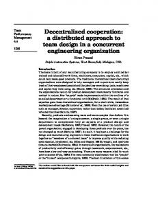
Fig. 4. String stability transfer function for different values of delay and headway time.
As with many other systems, the major factor affecting string stability is the delay in radar and wireless communications. To achieve a string stable platoon, we designed a PID controller to stabilize the system and minimizes the distance error, then by tuning the PID controller and changing the headway time, studied the string stability of the platoon for different values of delay. Fig. 4 illustrates the frequency response of the string stability signal for different delays and headway-times. The increased delay results in a larger magnitude in string stability signal, which means that the downstream vehicles will oscillate with a higher amplitude at higher delays. Increasing the headway time will improve the string stability and for each amount of the wireless delay there is a stabilizing minimum headway time. B. Platooning Constraint Handling String stability is not sufficient for safe and highperformance platooning. To ensure the vehicles’ safety and satisfactory performance, they must be able to handle constraints. The usual constraints in platooning are as follows: 1) Safety constraint: One of the platoon’s objectives is to minimize inter-vehicular distances to increase road throughput and to decrease drag while keeping a minimum distance for the safety. Thus, a maximum and minimum inter-vehicular distance error can be defined. Also, in platooning, it is necessary to have the minimum platoon length and based on that, a maximum inter-vehicular distance can be defined: epmin ≤ ep (t) ≤ epmax .
(9)
2) Limitation constraint: In real-world applications there are always constraints on the actuation limit. It is the same in platooning, with constraints on the maximum propulsion and maximum braking force: umin ≤ ui (t) ≤ umax .
(10)
The vehicles’ maximum and minimum allowable velocity is always limited and the limitation changes based on the route type and road condition: vmin ≤ vi (t) ≤ vmax .
(11)
(13)
These constraints ensure the performance and safety of platooning. It is necessary to employ a controller that is able to handle the platooning constraints. The string stability has a frequency-domain definition and combining it with constraint handling, which has a time-domain definition, is not trivial in a single controller. Here, to enforce the constraints, we have designed an RG that, if necessary, changes the reference to enforce the constraint handling. The main benefit of RG is that it separates the control design from the constraint handling, allowing classical popular control approaches to be used with no concern about the constraints. This benefit makes RG very useful in real-world applications since most control engineers are more comfortable with classical controllers, which are easier to tune and have been used for many years. In our case, in addition to the mentioned benefits, we are seeking to enforce the constraints on a string stable platoon without interfering with the main platoon control. RG works based on the system’s output admissible set. Definition 1: (Output Admissible Set) The output admissible set is the concatenated set of states and constant references that, if given to the system, will never violate the constraints on the output in the presence of a bounded disturbance [27]: O∞ = { (x(t), r(t)) | y(t + k) ∈ Y, ∀w(t + k) ∈ W, r(t + k) = r, ∀k ≥ 0}
(14)
where O∞ is the output admissible set, r is the constant reference, W is the disturbance bound and Y is the constraint on the output. Based on this set, RG will modify the reference to the system. If the original reference and states are inside O∞ , RG will not change the reference and, if necessary, RG will find the nearest reference that keeps the constraints. The problem with the classic RG is that it is assuming a constant reference, which limits its performance. Also, in realworld applications, O∞ (x(t)) can become void, which means there may be no constant reference that could maintain the constraints on the output. In this case, it is more practical to use a reference management, which is an extended version of RG. Reference management can work with void admissible sets by pushing the system toward admissibility in finite time. We define the new RG problem as presented in Algorithm 1. In Algorithm 1, s is a slack variable, �RG is a design parameter, τ shows the time in the prediction horizon, yi is the output, y¯d is the desired output, T is the terminal time, a ˆi−1 is the estimated acceleration set-point that comes through V2V communication and r is the generated reference by RG. ¯ a ˆi−1 , y¯i and r¯ respectively show the vector of the predicted
Algorithm 1 Reference Management Problem Input: {ˆ ai−1 , xi , yi } Output: {r}
Fig. 3 shows the location of RG in our platoon control architecture. RG will get the acceleration set-point of the preceding vehicle and, if the current states of the system are in the admissible set, will not change the acceleration setpoint. In the case of constraint violation, RG will move the system toward admissibility in a finite time by modifying the original reference. When the states are back in the output admissible set, RG will give the original reference to the system. This way, the platoon will be string stable and RG will only intervene when there is a chance of violating the constraints. To solve the problem stated in the algorithm 1, we used cvx, a package for specifying and solving convex optimizations [35],[36].
if a ˆi−1 6∈ O∞ (xi ) then activeRG ← T rue end if if activeRG == F alse then 5: r←a ˆi−1 6: else ¯ 7: min{k¯ yi − y¯d k2,Q + k¯ r−a ˆi−1 k2,R + ksk2,P } 1: 2: 3: 4:
r¯T
8: 9: 10: 11: 12:
s.t : xi (t + T ) ∈ O∞ (ˆ ai−1 ) yi (t + τ ) + s ∈ Y, τ = {0, 1, ..., T − 1} r ← r¯(1) if a ˆi−1 ∈ O∞ (xi ) & kr − a ˆi−1 k < �RG then activeRG ← F alse end if end if
C. Ecological Improvement
preceding vehicle’s acceleration, predicted output and vector of decision variables which its first component is given to the system as a reference value: r = r¯(1). Q, R and P represent the weightings on the output error, reference error and the slack variable. RG will determine if a ˆi−1 (t) ∈ O∞ (xi (t)), in this case, it does not change the original reference. But if a ˆi−1 (t) 6∈ O∞ (xi (t)), or if O∞ (xi (t)), is void, RG will move the system states toward the admissible set O∞ (ˆ ai−1 (t)) in a finite time while maintaining the constraints. The first term in the objective function of RG is the tracking term and the second term is the reference keeping term. Remark 1: The RG, added to the control system, will not change the autonomous system’s behavior when it recognizes that the constraints will not be violated. Therefore, if our original system is string stable, the new platooning system will remain string stable. In a situation where the constraints can be violated, RG will change the reference to keep the defined constraints and push the system toward the admissible set so it can give the original reference to the system and preserve the string stability. This will provide both string stability and constraint handling for the platoon. Remark 2: The design parameter �RG is set to avoid large changes when switching back to the original reference. A higher value of �RG will reduce the time window of active RG but might result in an oscillatory behavior. Remark 3: T , the minimum terminal time that can satisfy the condition: xi (T ) ∈ O∞ (ˆ ai−1 ), will be calculated using the method in [34]. To ensure the satisfaction of the terminal constraint, the terminal time must be set to a number larger than the minimum value. Remark 4: For a polytopic Y , an inner polytopic approximation of O∞ is available with the following form: ˜ ∞ = {(xi (0), r)| Hx xi (0) + Hr r ≤ c} O
(15)
where Hx , Hr and c are the polytope’s parameters. The accuracy of the approximation can be controlled by modifying a small value for approximation criteria [27].
The ecological performance improvement is done by the control of the lead vehicle. A smoother speed trajectory for the lead vehicle will result in lower energy costs for the whole platoon. The assumption for this section is that the leader is doing the car-following task because its preceding vehicle is neither connected nor part of the platoon. Because the leader’s controller is not considered in the frequency-domain string stability analysis, a time-domain approach can be used to control it. The following problem is defined for minimizing the energy cost of its car-following task [13]: Z tk +T J = (w1 e2p + w2 (v − vref )2 + w3 E(x, u, R))dt tk
subject to: x˙ i = F(xi , u, ai−1 ) vmin ≤ vi (t) ≤ vmax umin ≤ ui (t) ≤ umax (16) where ai−1 is the acceleration of the preceding vehicle. Inside the prediction horizon a prediction of the preceding vehicle’s acceleration is needed. Investigating standard drive cycles shows that the vehicles tend to move with low accelerations and at constant velocities [13], therefore, we used the following prediction, with an exponential decay in the acceleration: a ¯i−1 (τ ) = ai−1 (tk )e−λτ .
(17)
This model generates a prediction of the preceding vehicle’s acceleration over the prediction horizon. We are assuming that the preceding vehicle will reach a constant velocity and λ is a parameter for modifying this prediction. tk is the current time and τ is the prediction time. In (16), E is the energy cost as defined in the Eq.(5), R is the power ratio between the electric motors and the engine and T is the length of the prediction horizon that is chosen based on its effect on the energy economy and computation time [13], [37]. This cost function penalizes the inter-vehicular distance, velocity error and energy cost. We assume a constant power ratio in the prediction horizon that is equal to R and specified by the energy management controller at the current time instance. Therefore, the cruise controller will interact with the energy management system through this variable and different energy management techniques would result in separate ecological performances
(a)
Fig. 6. Identification results for string stability of the platoon with different headway times and communication delays
(b) Fig. 5. (a) Identification signal, with rich frequency content, used for string stability identification of the platoon. (b) close-up view of the identification signal. This velocity profile was given as reference to the platoon’s leader.
for the cruise control. The leader uses the control-oriented model to predict the future states of the system in the given prediction horizon. Based on this prediction, the objective function is evaluated and minimized in each time step to find the optimal control values. Then, in each time step, the first calculated input is given to the system as the control input. IV. C ONTROL E VALUATION In this section, the evaluation of the proposed controller is presented for string stability, constraint handling and ecological performance improvement. A platoon of vehicles was constructed in Simulink by combining six high-fidelity models of the baseline PHEV. The leader is controlled using the proposed NMPC for ecological car-following and the rest of the vehicles form a platoon that follows the leader. Each vehicle communicates with its immediate predecessor through V2V. It should be mentioned that, for the simulations, a linear Adaptive ECMS (A-ECMS) energy management method was used to optimize the power distribution between the vehicles energy sources [38], [39]. This method maintains a linear stateof-charge (SOC) profile during the trip based on the available route length. Energy management is not a focus of this paper; therefore it is not discussed here.
string stability for a high-fidelity platoon model. To evaluate the designed platoon’s string stability, we gave the leader a filtered white noise signal added to a constant velocity as the reference. Then, we measured the vehicles’ response for 1000 seconds and investigated the platoons string stability by calculating the frequency response between the lead and tail vehicles. To estimate the string stability frequency response function (FRF) from time-domain experimental data, it is necessary to use an excitation signal that is able to excite the frequency range of interest [32], [40]. Therefore, we chose a colored noise signal, generated by filtering a white noise signal that has a reach frequency content and it is appropriate for assessments of the FRF of the system. Fig. 5 shows the reference signal used for system identification. This signal has a rich frequency content and is suitable for the identification of the platoon’s model. The transfer function estimation was performed by the tfestimate command in Matlab with 16384 windows and 50% overlap. Fig. 6 illustrates the magnitude of the transfer function generated in the identification test between the accelerations of the lead and tail vehicles. The frequency analysis shows a result similar to that in Fig. 4, for different values of delay and headway time. Using this method, we chose a constant headway time equal to 0.6 for the presented simulations and considered a wireless delay equal to 0.15 seconds in the V2V communications.
A. String Stability Since the reference governor does not change the regular behaviour of the system, the platoon will remain string stable. To show the validity of this statement, we have performed a string stability identification test on the vehicle platoon. This test will determine if the designed controllers can achieve
Fig. 7. Projection of the calculated output admissible set for three different preceding vehicle’s acceleration set-points. In this plot, the blue color has priority to green and green has priority to red. Therefore the overlapping areas are shown with the color of higher priority.
B. Constraint Handling The next step after designing the string stable platoon is to enforce the defined constraints on the system. As explained above, the RG approach was used for constraint handling. RG works based on the output admissible set; therefore, the first step in designing RG is calculating this set. The discretized version of the model presented in (3) was used to calculate the output admissible set. A polytypic inner approximation of the output admissible set was generated using the method presented in [26], [27]. Fig. 7 illustrates projections of three states of the output admissible sets for three different values of the preceding vehicle’s accelerations. Fig. 7 is only generated to show the general behavior of the output admissible set. The constraints that we assumed in this case are on the position error, velocity error and acceleration limits. The velocity profile in Fig. 8 was used, therefore, a constraint on the distance error was chosen as: ep ∈ [−0.6 0.75] to avoid infeasibility. The constraint on the inter-vehicular velocity was chosen as ev ∈ [−5 5] to avoid large velocity difference but allowing vehicles to have slightly different speeds. The acceleration
(a)
(b) Fig. 9. Control signal generated by RG (red dashed line) and original acceleration set-point of the preceding vehicle in: (a) first vehicle and (b) second vehicle.
(a)
(b)
(c) Fig. 8. (a) Velocity profile of the platoon’s first three vehicles following a reference vehicle. (b) Acceleration profile of the vehicles in platoon. (c) Inter-vehicular distance error of the first three vehicles in platoon.
limit was chosen as: ai ∈ [−5 2.5] based on the available actuation in the vehicle. The output admissible set contains the points in the state space that are safe in terms of handling the constraints for the specified reference value. Therefore, if, for example, the preceding vehicle’s acceleration set-point ap is equal to -1 and states are in the red region, the defined constraint will not be violated. However, if the system’s states are not in the red region, giving ap , as reference to the CACC controller will result in the violation of the defined constraints. In this case RG becomes active, moves the states back into the red region and then becomes inactive. RG pushes the system states inside the presented output admissible set to enforce the defined constraints. To evaluate performance of the RG, the same platoon as the previous section was used in Simulink. To have clearer test figures, only the results of the first three platoon vehicles were plotted in this section. Fig. 8 illustrates the performance of the designed platoon in following a reference vehicle. It can be seen that the platoon is string stable and there is less oscillation for the follower vehicle compared to the proceeding ones. The vehicles follow each other by a reasonable acceleration and velocity. Fig. 8 (c) shows the inter-vehicular distance error between the three vehicles. The distance error is mostly well behaved and inside the defined constraints, only in 1122 and 1147 seconds the distance error reaches the lower limit of -0.6m. Fig. 9 shows the reference generated by RG and the original references for the two follower vehicles in the same drive cycle. It can be seen that in 1122 seconds, RG has modified the original reference for about five seconds to avoid constraint violations. In 1147 seconds, the distance error reaches -0.6m but RG does not modify the reference because
TABLE I P LATOON ’ S ENERGY COST FOR DIFFERENT LEADER CONTROLLER Energy Cost ($) Leader’s Controller
Fig. 10. Speed trajectory of platoon vehicles following FTP-75 standard drive cycle.
it recognizes that the system remains inside the constraint with the original CACC reference. C. Ecological Improvement The ecological performance improvement is done by controlling the leader to achieve smoother speed trajectories with reduced unnecessary accelerations. The designed NMPC controller minimizes the energy cost of the leader. Because in a string stable platoon, the follower vehicles try to follow the same trajectory as the leader with reduced oscillations, it is expected that the followers will have a better energy economy. Thus, a higher energy efficiency can be achieved for the whole platoon. Fig. 10 shows the speed trajectory of a string stable platoon of vehicles following the FTP-75 driving cycle. As it can be seen, the tail vehicle has a much smoother speed trajectory compared to the leader which is because of the platoon’s string stability. This smoother trajectory will result in less unnecessary accelerations and a better energy economy for the platoon. Fig. 11 and Table I show the total trip energy cost of the vehicles in the platoon. As expected, for three consecutive FTP-75 drive cycles, the lead vehicle has the highest energy consumption ($1.85), followed by the last two vehicles ($1.74). Therefore, the tail vehicle has a 6% lower energy cost compared to the lead vehicle that has already reduced its energy cost using an ecological ACC for car-following. In the case of the leader with PID controller, the tail vehicle has a 12% lower energy cost compared to the leader. The trend in the energy consumption of the string of vehicles suggests that, in the proposed platoon design, there is a limit in the improved energy cost caused by the reduced unnecessary acceleration and deceleration. The oscillations in the lead vehicle’s velocity profile get attenuated in the string of vehicles and they vanish after a number of vehicles. After that, the other followers have a very close velocity profile, and therefore a similar energy consumption. Fig. 12 and Table I show the total trip energy cost of the platoon in three consecutive FTP-75 drive cycles. The platoon with the proposed NMPC leader controller has an energy cost of $10.64 which is about 6% lower than the platoon with PID leader, which has an energy cost of $11.32.
1st
2nd
Car
Car
3rd Car
4th Car
5th Car
6th Car
Sum
PID
2.06
1.94
1.86
1.83
1.83
1.81
11.32
NMPC
1.85
1.79
1.76
1.75
1.74
1.74
10.64
The presented Eco-ACC controller for the leader has resulted in a 10% lower energy cost for the leader. It has also resulted in lower energy costs for the follower vehicles, compared to a regular PID controller. The tail vehicle in NMPC lead platoon consumed about 3.9% less energy compared to the tail vehicle in the PID lead platoon. These results are a comparison between platoons with different leaders and do not show the improvements caused by platooning. Here, we have only considered the energy cost improvement due to minimizing unnecessary accelerations and decelerations in the vehicle platoon. A lower energy cost is also expected because of the platoon’s reduced drag; however, our simulations did not consider the effect of the reduced drag due to its uncertain and complex behavior. Moreover, in passenger cars, lower drag in follower vehicles is only noticeable in inter-vehicular distances, at least, less than the length of the vehicle [41],[42]; however, considering the safety requirements, network imper-
Fig. 11. Total energy cost for each vehicle in the platoon following the FTP75 driving cycle.
Fig. 12. Total energy cost of the whole platoon following the FTP-75 driving cycle with PID and NMPC controlled leaders.
(a)
designed controllers; and a human-machine interface, which is a computer used for programming the real-time machine and the prototype ECU, as well as for recording the desired output signals. All communication between the prototype ECU and the real-time machine is performed through a Controller Area Network (CAN). For the HIL tests, only two vehicles were considered, a follower that runs the proposed controller and a leader. The platooning controller with RG was uploaded to the test ECU to evaluate its computation time. Fig. 13 shows the velocity and position error during the HIL experiment and Fig. 14 shows the turnaround time of the ECU running the proposed platooning controller. In regular situations when RG only checks the admissibility, the turnaround time of the controller is about 0.05ms. When RG detects a chance for violation of the constraints, it becomes active; therefore, the turnaround time of the controller increases for a limited time. Even when there is an increase in the computations, the turnaround time is below 1ms. To better illustrate the performance of the controller, only a part of the experiment has been shown in Fig. 13.
(b) Fig. 13. (a) Speed and (b) position error of the leader and the first follower vehicle during the HIL experiment
fections and string stability, such low distances are not currently feasible for practical platooning of passenger vehicles. In summary, the effect of the reduced drag on the indicated ecological performance results will not be significant. D. Real-time Implementation To further examine the performance of the proposed controller, hardware-in-the-loop (HIL) experiments have been carried out to ensure the potential and capability of the controller for real-time implementations in practice. dSPACE MicroAutobox II control prototyping hardware was used for HIL tests, which is one of the widely used instruments for testing and calibration of ECUs specially for automotive applications [43]. The HIL setup consists of three main components: a realtime machine (DS1006 processor board), which is a powerful and fast processor that can run the complex high-fidelity model in a real-time fashion; a prototype ECU (MicroAutoBox II), which is an independent processing module that runs the
Fig. 14. Turnaround time of the ECU during the HIL experiment.
V. C ONCLUSION This work has targeted an important issue in the platooning of vehicles: the simultaneous satisfaction of frequency-domain criteria, namely the string stability and time-domain criteria, that is, the constraint handling. The RG approach was proposed to enforce the constraints while preserving the string stability of the designed platoon. In the first step, a control-oriented model was presented to be used in platooning and ecological control of the baseline PHEV, namely Toyota plug-in Prius. The linear platooning model was used in the RG design and the nonlinear PHEV model was used in the heart of the NMPC to control the lead vehicle. A high-fidelity model of the baseline PHEV was used to evaluate the controllers and validate the control-oriented model. The linear platooning controllers were designed to achieve a string stable platoon based on the induced norm and the platooning model proposed in the modeling section. Then, the RG-based controller was designed to enforce the defined constraints on the stable system. The RG sits behind the CACC controller and, by getting the host vehicle’s states and the preceding vehicle’s acceleration set-points from a wireless network, modifies the reference signal to keep the defined constraints. RG produces the same reference as its input to the system and only changes it when it recognizes a possibility for violation of the constraints. Therefore, based on the first step’s design, the platoon remains string stable and can handle the platooning constraints. To improve the platoon’s energy economy, an ecological ACC was presented that enables the lead vehicle to follow an unconnected preceding vehicle that is not part of the platoon. Follower vehicles consume less energy, as they follow the same trajectory as the leader, with reduced oscillations due to string stability. Therefore, as suggested in the existing literature, there is no need to control each vehicle separately and specifically for improving its energy economy. This control
approach combines string stability; safety and performance constraints handling; and energy economy improvement and satisfies all of them at the same time. A frequency-domain analysis showed that the proposed controller results in a string stable platoon based on the controller design. The result for constraint satisfaction demonstrated that RG is able to keep the system inside the defined constraints only by modifying the original reference to the CACC controller. As shown in Fig. 9, the added RG did not change the general behavior of the controlled system and only intervened when there was a chance for constraint violation. Consequently, the system remained string stable and was able to handle the defined constraints. The major contribution of this work is that the proposed control approach has separated the main platooning design for car-following and string stability from constraint handling. Results show that a platoon whose leader had the NMPC controller recorded an ecological improvement of about 6%, compared to one with a PID controller. The follower vehicles have up to 10% lower energy costs compared to the leader, which is due to the string stable platooning. The HIL test with a dSPACE setup showed that, on average, the proposed controllers have low computation costs with increased turnaround time only when RG becomes active. However, the turnaround time is below 1ms in all cases. R EFERENCES [1] A. Paul, R. Chauhan, R. Srivastava, and M. Baruah, “Advanced Driver Assistance Systems,” SAE Technical Paper, Tech. Rep. 0148-7191, 2016. [2] P. Blythe and A. Curtis, “Advanced driver assistance systems: Gimmick or reality,” in 11th World Congress on ITS, Nagoya, 2004. [3] A. Vahidi and A. Eskandarian, “Research advances in intelligent collision avoidance and adaptive cruise control,” Intelligent Transportation Systems, IEEE Transactions on, vol. 4, no. 3, pp. 143–153, 2003. [4] B. Van Arem, C. J. Van Driel, and R. Visser, “The impact of cooperative adaptive cruise control on traffic-flow characteristics,” IEEE Transactions on Intelligent Transportation Systems, vol. 7, no. 4, pp. 429–436, 2006. [5] A. Touran, M. A. Brackstone, and M. McDonald, “A collision model for safety evaluation of autonomous intelligent cruise control,” Accident Analysis & Prevention, vol. 31, no. 5, pp. 567–578, 1999. [6] N. A. Stanton and M. S. Young, “Driver behaviour with adaptive cruise control,” Ergonomics, vol. 48, no. 10, pp. 1294–1313, Aug. 2005. [Online]. Available: http://dx.doi.org/10.1080/00140130500252990 [7] C.-Y. Liang and H. Peng, “String Stability Analysis of Adaptive Cruise Controlled Vehicles,” JSME International Journal Series C, vol. 43, no. 3, pp. 671–677, 2000. [8] A. Bose and P. Ioannou, “Evaluation of the environmental effects of intelligent cruise control vehicles,” Transportation Research Record: Journal of the Transportation Research Board, no. 1774, pp. 90–97, 2001. [9] L.-h. Luo, H. Liu, P. Li, and H. Wang, “Model predictive control for adaptive cruise control with multi-objectives: comfort, fuel-economy, safety and car-following,” Journal of Zhejiang University SCIENCE A, vol. 11, no. 3, pp. 191–201, 2010. [10] M. Wang, W. Daamen, S. P. Hoogendoorn, and B. van Arem, “Driver assistance systems modeling by model predictive control,” in 15th International IEEE Conference on Intelligent Transportation Systems, Sept 2012, pp. 1543–1548. [11] M. A. S. Kamal, M. Mukai, J. Murata, and T. Kawabe, “Model Predictive Control of Vehicles on Urban Roads for Improved Fuel Economy,” IEEE Transactions on Control Systems Technology, vol. 21, no. 3, pp. 831– 841, 2013. [12] M. A. S. Kamal, J. i. Imura, T. Hayakawa, A. Ohata, and K. Aihara, “Smart Driving of a Vehicle Using Model Predictive Control for Improving Traffic Flow,” IEEE Transactions on Intelligent Transportation Systems, vol. 15, no. 2, pp. 878–888, 2014.
[13] M. Vajedi and N. L. Azad, “Ecological Adaptive Cruise Controller for Plug-In Hybrid Electric Vehicles Using Nonlinear Model Predictive Control,” Intelligent Transportation Systems, IEEE Transactions on, vol. PP, no. 99, pp. 1–10, 2015. [14] A. A. Alam, A. Gattami, and K. H. Johansson, “An experimental study on the fuel reduction potential of heavy duty vehicle platooning,” in 13th International IEEE Conference on Intelligent Transportation Systems, Sept 2010, pp. 306–311. [15] J. W. Forrester, “Industrial dynamics,” Journal of the Operational Research Society, vol. 48, no. 10, pp. 1037–1041, 1997. [16] M. Cantoni, E. Weyer, Y. Li, S. K. Ooi, I. Mareels, and M. Ryan, “Control of large-scale irrigation networks,” Proceedings of the IEEE, vol. 95, no. 1, pp. 75–91, Jan 2007. [17] P.-H. Lin, D. S.-H. Wong, S.-S. Jang, S.-S. Shieh, and J.-Z. Chu, “Controller design and reduction of bullwhip for a model supply chain system using z-transform analysis,” Journal of Process Control, vol. 14, no. 5, pp. 487–499, 2004. [18] D. Swaroop and J. K. Hedrick, “String stability of interconnected systems,” IEEE Transactions on Automatic Control, vol. 41, no. 3, pp. 349–357, 1996. [19] L. Peppard, “String stability of relative-motion PID vehicle control systems,” Automatic Control, IEEE Transactions on, vol. 19, no. 5, pp. 579–581, 1974. [20] R. Kianfar, P. Falcone, and J. Fredriksson, “A control matching model predictive control approach to string stable vehicle platooning,” Control Engineering Practice, vol. 45, pp. 163–173, 2015. [21] J. Ploeg, N. v. d. Wouw, and H. Nijmeijer, “Lp String Stability of Cascaded Systems: Application to Vehicle Platooning,” IEEE Transactions on Control Systems Technology, vol. 22, no. 2, pp. 786–793, 2014. [22] R. Kianfar, P. Falcone, and J. Fredriksson, “Reachability analysis of cooperative adaptive cruise controller,” in Intelligent Transportation Systems (ITSC), 2012 15th International IEEE Conference on. IEEE, 2012, pp. 1537–1542. [23] A. Alam, A. Gattami, K. H. Johansson, and C. J. Tomlin, “Guaranteeing safety for heavy duty vehicle platooning: Safe set computations and experimental evaluations,” Control Engineering Practice, vol. 24, pp. 33–41, 2014. [24] W. B. Dunbar and D. S. Caveney, “Distributed receding horizon control of vehicle platoons: Stability and string stability,” IEEE Transactions on Automatic Control, vol. 57, no. 3, pp. 620–633, 2012. [25] R. Kianfar, P. Falcone, and J. Fredriksson, “A distributed model predictive control approach to active steering control of string stable cooperative vehicle platoon,” vol. 7, 2013, pp. 750–755, 1. [26] U. Kalabic, “Reference governors: Theoretical extensions and practical applications,” Ph.D. dissertation, Ford Motor Company, 2015. [27] I. Kolmanovsky, E. Garone, and S. Di Cairano, “Reference and command governors: A tutorial on their theory and automotive applications,” in American Control Conference (ACC), 2014. IEEE, 2014, pp. 226– 241. [28] V. Turri, B. Besselink, and K. H. Johansson, “Cooperative Look-Ahead Control for Fuel-Efficient and Safe Heavy-Duty Vehicle Platooning,” IEEE Transactions on Control Systems Technology, vol. PP, no. 99, pp. 1–17, 2016. [29] B. HomChaudhuri, A. Vahidi, and P. Pisu, “A fuel economic model predictive control strategy for a group of connected vehicles in urban roads,” Jul. 2015, pp. 2741–2746. [30] ——, “Fast Model Predictive Control-Based Fuel Efficient Control Strategy for a Group of Connected Vehicles in Urban Road Conditions,” IEEE Transactions on Control Systems Technology, vol. PP, no. 99, pp. 1–8, 2016. [31] R. Rajamani, Vehicle dynamics and control. Springer Science & Business Media, 2011. [32] S. nc, J. Ploeg, N. van de Wouw, and H. Nijmeijer, “Cooperative adaptive cruise control: Network-aware analysis of string stability,” IEEE Transactions on Intelligent Transportation Systems, vol. 15, no. 4, pp. 1527–1537, Aug 2014. [33] M. Vajedi, A. Taghavipour, and N. L. Azad, “Traction-motor power ratio and speed trajectory optimization for power split PHEVs using route information.” American Society of Mechanical Engineers, 2012, pp. 301–308. [34] K. Kogiso and K. Hirata, “Reference governor for constrained systems with time-varying references,” Robotics and Autonomous Systems, vol. 57, no. 3, pp. 289–295, 2009. [35] M. C. Grant and S. P. Boyd, “Graph implementations for nonsmooth convex programs,” in Recent advances in learning and control. Springer, 2008, pp. 95–110.
[36] M. Grant, S. Boyd, and Y. Ye, “CVX: Matlab software for disciplined convex programming,” 2008. [37] S. Tajeddin, M. Vajedi, and N. L. Azad, “A newton/gmres approach to predictive ecological adaptive cruise control of a plug-in hybrid electric vehicle in car-following scenarios,” IFAC-PapersOnLine, vol. 49, no. 21, pp. 59–65, 2016. [38] M. Vajedi, M. Chehrehsaz, and N. L. Azad, “Intelligent power management of plug–in hybrid electric vehicles, part i: real–time optimum soc trajectory builder,” International Journal of Electric and Hybrid Vehicles, vol. 6, no. 1, pp. 46–67, 2014. [39] ——, “Intelligent power management of plug–in hybrid electric vehicles, part ii: real–time route based power management,” International Journal of Electric and Hybrid Vehicles, vol. 6, no. 1, pp. 68–86, 2014. [40] L. Ljung, System identification. Wiley Online Library, 1999. [41] B. Marcu and F. Browand, “Aerodynamic forces experienced by a 3vehicle platoon in a crosswind,” SAE Technical Paper, Tech. Rep., 1999. [42] M. Michaelian and F. Browand, “Field experiments demonstrate fuel savings for close-following, california path program, institute of transportation studies,” University of California at Berkeley, 2000. [43] A. Mozaffari, N. L. Azad, A. Hansen, and J. K. Hedrick, “A Receding Horizon Sliding Controller for Automotive Engine Coldstart: Design and HardwareintheLoop Testing With an Echo State Network HighFidelity Model,” Asian Journal of Control, vol. 18, no. 4, pp. 1219–1238, 2016.