the second-generation (digital) microfluidic biochips, which are based on the manipulation of discrete microliter or nanoliter liquid particles (the droplets), have ...
A Fast Routability- and Performance-Driven Droplet Routing Algorithm for Digital Microfluidic Biochips Tsung-Wei Huang and Tsung-Yi Ho∗ Department of Computer Science and Information Engineering National Cheng Kung University, Tainan, Taiwan
Abstract
(e.g., dilute, mix, etc.) can be performed anywhere in the 2D microfluidic array because each basic cell has the same architecture. Besides the 2D microfluidic array, there are on-chip reservoirs/dispensing ports and optical detectors. The dispensing port/reservoirs are responsible for droplet generation while the optical detectors are used for droplet detection. Electrodes are connected to control pins for electrical actuation. Therefore, by controlling voltage to each electrode in the bottom glass plate with control pins, we can control the moving direction of droplets. One of the critical steps in DMFB physical design is the droplet routing problem [9]. The main challenge of droplet routing is to ensure the correctness of a bioassay; the fluidic property which avoids unexpected mixing among droplets needs to be satisfied. The dynamic reconfigurability inherent in DMFBs allows different droplet routes to share cells on the microfluidic array during different time intervals. Unlike traditional VLSI routing, in addition to routing path selection, the droplet routing problem needs to address the issue of scheduling droplets under the practical constraints imposed by the fluidic property and the timing restriction of the synthesis result [12, 13]. In this paper, we propose a fast routability- and performancedriven droplet router for DMFBs. Different from the aforementioned works, our algorithm has the following distinguished features:
As the microfluidic technology advances, the design complexity of digital microfluidic biochips (DMFB) are expected to explode in the near future. One of the most critical challenges for DMFB design is the droplet routing problem, which schedules the movement of each droplet in a time-multiplexed manner. In this paper, we propose a fast routability- and performancedriven droplet router for DMFBs. The main contributions of our work are: (1) a global moving vector analysis for constructing preferred routing tracks to minimize the number of used unit cells; (2) an entropy-based equation to determine the routing order of droplets for better routability; (3) a routing compaction technique by dynamic programming to minimize the latest arrival time of droplets. Experimental results show that our algorithm achieves 100% routing completion for all test cases on three Benchmark Suites while the previous algorithms are not. In addition to routability, compared with the state-of-theart high-performance routing on the Benchmark Suite I [3], the experimental results still show that our algorithm performed better in runtime by 40%, reduced the latest arrival time by 21%, reduced the used unit cells by 10%. Furthermore, experiment results on Benchmark Suite II and III are also very promising. Based on the evaluation of three Benchmark Suites, our algorithm demonstrates the efficiency and robustness of handling complex droplet routing problem over the existing algorithms.
• A global moving vector analysis for constructing preferred routing tracks to minimize the number of used unit cells.
1 INTRODUCTION As the advances in microfabrication and microelectromechanical systems (MEMS), the microfluidic technology has gained much attention recently. Promising applications of this emerging technology include high-throughput DNA sequencing, immunoassays, environmental toxicity monitoring, and point-ofcare diagnosis of diseases. Microfluidics-based miniaturized devices, often referred to in the literature as biochips or lab-onchip [6], are being increasingly used for laboratory procedures involving molecular biology. The first generation of microfluidic biochips were based on manipulating continuous liquid flows using several micrometerscale components including channels, valves, actuators, sensors, pumps, and so on [7, 11]. Although they have been successfully applied to many biological applications, their lack of reconfigurability makes unsuitable for large scale systems. Recently, the second-generation (digital) microfluidic biochips, which are based on the manipulation of discrete microliter or nanoliter liquid particles (the droplets), have been proposed [9]. Such droplets are manipulated independently by the electrohydrodynamic forces generated by an electric field [2]. The field can be generated by an individually accessible electrode. This new generation is referred to as a digital microfluidic biochip (DMFB). The basic cell of a DMFB consists of two parallel glass plates. The bottom plate contains a patterned array of individually controllable electrodes, and the top plate is coated with a continuous ground electrode. The droplets containing biochemical samples, and the filler medium, such as silicone oil, are sandwiched between the plates. By varying the electrical potential along a linear array of electrodes, droplets can be moved along this line of electrodes due to the principle of electrowetting on dielectric (EWOD) [2, 8]. The basic operations
• An entropy-based equation to determine the routing order of droplets for better routability. • A routing compaction technique by dynamic programming to minimize the latest arrival time of droplets. Experimental results show that our algorithm achieves 100% routing completion for all test cases on three Benchmark Suites while the previous algorithms are not [1, 3, 14]. In addition to routability, compared with the state-of-the-art high-performance routing on the Benchmark Suite I [3], [3], the experimental results still show that our algorithm performed better in runtime by 40%, reduced the latest arrival time by 21%, reduced the used unit cells by 10%. Furthermore, experiment results on Benchmark Suite II and III are also very promising. Based on the evaluation of three Benchmark Suites, our algorithm demonstrates the efficiency and robustness of handling complex droplet routing problem over the existing algorithms. The rest of this paper is organized as follows. Section II presents previous work and problem formulation of droplet routing problem. Section III gives the overall algorithm for DMFB routing. Experimental results are discussed in Section IV. Finally, concluding remarks are given in Section V.
2
2.1 Previous Work Droplet routing is a critical step in DMFB physical design automation. Unlike traditional VLSI routing, in addition to routing path selection, the droplet routing problem needs to address
∗ Tsung-Yi Ho’s work was partially supported by the National Science Council of Taiwan ROC under Grant No. NSC 96-2220-E-006-013.
978-1-4244-5028-2/09/$25.00 ©2009 IEEE
DROPLET ROUTING ON DMFBS
In this section, we first discuss the previous work on droplet routing for DMFBs. Then we present the problem formulation of the droplet routing problem.
445
the issue of scheduling droplets under the practical constraints imposed by the fluidic property and the timing restriction of the synthesis result. To tackle this problem, B¨ohringer proposed the prioritized A*-search algorithm to coordinate each droplet based on its priority [1]. However, it can only handle two-pin connections and the practical timing constraint is not considered due to the simple priority assignment. Griffith et al. proposed a pattern selection method that is based on the open shortest path first routing protocol [5]. Since droplet movement is only limited to the fixed layout patterns, this approach does not exploits the important benefits such as dynamic reconfigurability. Su et al. proposed a two-stage algorithm that adopts maze routing followed by random selection and scheduling for selected routing paths [10]. Yuh et al. also proposed a two-stage algorithm of global routing followed by detailed routing [14]. In global routing, it adopts network-flow-based global routing algorithm to route a set of non-interfering nets concurrently. In detailed routing, it applies negotiation-based routing scheme for simultaneous routing and scheduling. However, the network-flow formulation is significantly bottlenecked by the distribution of blockages. To conservatively guarantee the fluidic constraint, a channel with at least three cells is considered in the networkflow formulation. Hence, if the width of the channel between blockages is less than three cells (even though a droplet can pass it), the channel will not be utilized in the network-flow formulation, resulting in suboptimal solutions in terms of routability. In [3], a novel high-performance routing algorithm is proposed for DMFB droplet routing, showing better routability than all previous works. However, the routing order arranged by the simple bypassibility analysis may be imprecise because it only considers the congestion around the target cells. In other words, the droplet with higher bypassibility may still suffer from either detours or deadlocks in the routing path. Furthermore, the routing compaction steps reroute each droplet in a greedy manner will increase computational complexity significantly.
formulation of one 2D plane. Other 2D planes can be handled similarly. The droplet routing problem on a 2D plane can be formulated as follows: Input: A netlist of n droplets D = {d1 , d2 , . . . , dn }, the locations of blockages, and the timing constraint Tmax . Objective: Route all droplets from their source cells to their target cells while minimizing the latest arrival time among all droplets and the number of unit cells for better fault tolerance. Constraint: Both fluidic and timing constraints are satisfied.
3
ALGORITHM
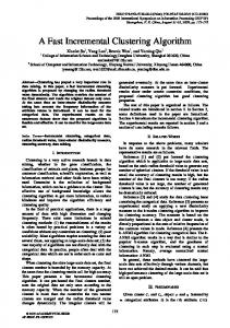
In this section, we propose our droplet routing algorithm for DMFB design. The main steps of our algorithm are: (1) A global moving vector analysis for constructing preferred routing tracks to minimize the number of used unit cells; (2) an entropy-based equation to determine the routing order of droplets for better routability; (3) a routing compaction technique by dynamic programming to minimize the latest arrival time of droplets. In constructing the preferred routing tracks, we first set a global routing direction for non-adjacent tracks on the microfluidic array, then update the original routing direction by analyzing each droplet’s moving vector, which is discussed in Section 3.1. In section 3.2, we define the variant of entropy and the energy system of droplets to determine the routing order of droplets for better routability. In section 3.3, we propose a dynamic programming approach to compact the latest arrival time among all droplets, and delete the duplicate routing paths if they exist. 3.1 Preferred Routing Tracks Construction The goal of droplet routing in a DMFB is to find an efficient schedule for each droplet from its source to target while both fluidic and timing constraint are satisfied. Furthermore, it is desirable to minimize the latest arrival time among all droplets and the number of unit cells used during routing for fault tolerance. However, with the increasing design complexities, there may exist substantial blockages in a DMFB that cause fatal routability problems. Moreover, as multiple droplets are routed in a time-multiplex manner, violations of fluidic constraint occur frequently, involving deadlock or detour overhead that increase the used unit cells. To remedy these deficiencies, we construct the preferred routing tracks in the microfluidic array to make droplets route on specific tracks orderly. Consider a 13 × 13 microfluidic array with 6 droplets in Figure 1 (a). We first construct global routing tracks on non-adjacent rows and columns in the microfluidic array as shown in Figure 1 (b), and the rest of the cells are left for detour routing. Then we analyze the moving vectors of each droplet and update the preferred routing direction of the routing tracks. The moving vectors of a droplet di only exist on the cells in the global routing tracks within its bounding box BBdi of source cell sdi and target cell tdi except for the blockages. If the cells inside BBdi are in the horizontal global routing tracks where the x-coordinate of tdi is greater or equal to (less than) it of sdi , the moving vector will be → (←). On the contrary, if the cells inside BBdi are in the vertical global routing tracks where the y-coordinate of tdi is greater or equal to (less than) it of sdi , the moving vector will be ↑ (↓). If there are many moving vectors against the original global setting, we will change the direction of routing tracks. For example, in Figure 1 (b), the global routing direction of the topmost row is initially set to be right, after analyzing the moving vector of each droplet, there are total 7 left moving vectors on row 1 contributed by droplet 1 (3 ←), droplet 3 (1 ←), and droplet 4 (3 ←). Thus, we change the preferred routing track of row 1 to be left as shown in Figure 1 (c). The intuition behind our preferred routing tracks construction is similar to traffic control, as each droplet can be regarded as a car. If most of the cars have common driving direction on the global routing track, we will assign the track to the preferred driving direction, which is beneficial to the traffic control (avoid the conflicts of fluidic constraints). If these cars did not drive on the preferred routing track, they can still drive the alternative shoulders adjacent to it or even the opposite direction of it, but
2.2 Problem Formulation There are two routing constraints in droplet routing: the fluidic constraint and the timing constraint. The fluidic constraint is used to avoid the unexpected mixtures between two droplets of different nets during their transportation and it can further be divided into the static and dynamic fluidic constraints [10]. Let di at (xti , yit ) and dj at (xtj , yjt ) denote two independent droplets at time t. Then, the following constraints should be satisfied for any t during routing: • Static constraint: |xti − xtj | > 1 or |yit − yjt | > 1. • Dynamic constraint: |xt+1 − xtj | > 1 or |yit+1 − yjt | > 1 i t+1 t or |xti − xt+1 | > 1. j | > 1 or |yi − yj The static fluidic constraint states that the minimum spacing between two droplets is one cell for any t during routing. The dynamic fluidic constraint states that the activated cell for di cannot be adjacent to dj . The reason is there can be more than one activated neighboring cell for dj . Therefore, we may have an unexpected mixing between di and dj . Besides the fluidic constraint, there exists the timing constraint. The timing constraint specifies the maximum arrival time of a droplet from its source to target. For fast bioassay execution or better reliability, it is desirable to minimize the latest arrival time among all droplets. Furthermore, it is desirable to minimize the number of unit cells that are used during routing. Since a unit cell of a DMFB can be defective due to manufacturing or environmental issues, using a smaller number of unit cells for routing can be beneficial for robustness. Since the problem can be abstracted as transporting each droplet from its source to target, we cast droplet routing into a graph search as done in VLSI routing. As resource sharing in a time-multiplexed fashion is allowed in a DMFB, we can model it as a 3-D graph where z-axis is for time, which enables one to optimize geometric paths and temporal schedules simultaneously. Since we can sequentially route each 2D plane to form a complete droplet routing solution, we only show the problem 446
�� �
��
�� � �
��
��
��
��
��
��
�
�
��
��
/0 6 0
65
/1
$* +%
$) +(
£¤ ª¤
$(
��
��
�
�
��
+&
$'
���
�
��
+*
�
� ��
��
$&
��
��
�
$% +'
�
��
�� ��
� �
��
�
£¥
:; A =
+)
!"#
:
£¦
,-.
EK L F
:?
ª¨
/3
/2
ª©
�
�
�
Figure 1: This example illustrates the proposed algorithm by a 13 × 13 microfluidic array with 6 droplets in (a)–(h). (a) An example routing problem. (b) Initial global routing tracks. (c) Updated preferred routing tracks by analyzing moving vectors of droplets. (d) The energy system of droplet 5. (e) Droplet 5 is backing off due to the passing of droplet 2. (f) All droplets are routed to their A-cells. (g) Routing paths of all droplets. (h) Final routing paths of all droplets after the duplicated paths are deleted.
�
they will be charged for additional costs (minimize the used unit cells). We model the routing resource as a routing graph G = (V, E). A node in the routing graph represents a cell in the microfluidic array, whereas an edge denotes the connection between two adjacent cells. The droplet routing result Rdi = {c ∈ V |c is the cell chosen for routing }. For the traffic control, we define the cost function of the droplet routing result Rdi as follows:
�
�
c∈Rd
�� �
��
�
��
��
��
�
�
� �� �
(α · Clegal + β · Cillegal + γ · Cshoulder )
�
�
X Cost(Rdi ) =
�
�
��
��
��
�
(1)
����� ��
i
��
�
��
�� ��
��
����� �� ������ � �� ��
�� � ���� �� ������ � �� ��
Figure 2: Two test cases in Benchmark Suite II: (a) Test b. (b) Test d.
where α, β, and γ are user-specified parameters. Clegal , Cillegal , and Cshoulder are the cost of the cell that is along the preferred routing tracks, against the preferred routing tracks, and in the shoulders associated with di , respectively. The goal is to make droplets route along the preferred routing tracks and find the minimum cost path. If there is a tie in terms of cost, we encourage it to share the path taken by the previous droplets to improve routability as well as fault tolerance.
In thermodynamics, entropy is a measure of the unavailability of a system’s energy to do work. It is a measure of the randomness of molecules in a system and is central to the second law of thermodynamics and the fundamental thermodynamic relation, which deals with physical processes and whether they occur spontaneously. For a constant temperature, the variant in entropy can be defined in the following differential equation:
3.2 Entropy-Based Equation for Routing Order A key issue in the droplet routing problem is the determination of the droplet routing order. If droplets route in disorder, it will cause fatal routability problems, which increases the routing complexity. For example, if we adopt the bypassibility analysis [3] which only considers the congestion around the target cell to arrange the routing order. In Figure 2 (a), droplet 1 and 2 will route before droplet 3 due to the higher bypassibility, but they will block the routing path of droplet 3 completely. Moreover, in Figure 2 (b), droplet 1 will be routed first for full bypassibility, but it will suffer from many concession detours contributed by droplet 2, 3, 4, 5, and 6. Thus, we should consider the congestion of routing region between source and target cells of droplets instead of target cell only. To solve this problem, we propose an entropy-based equation which considers the congestion of routing region globally to determine the routing order of droplets for better routability.
dS =
dQ T
(2)
where dS is the variant of entropy, dQ is the amount of heat absorbed in an isothermal and reversible process in which the system goes from one state to another, and T is the absolute temperature at which the process is occurring. Inspired from the idea of entropy, we define the variant of entropy to measure the routability inside the routing region of each droplet in the following discrete formulation: ∆BEdi =
447
∆Qdi ESdi
(3)
TABLE I: NOTATIONS USED IN OUR ENTROPY-BASED FORMULATION. ESdi energy system of a droplet di ∆BEdi variant of entropy inside ESdi ∆Qdi variant of energy inside ESdi Ebi energy of the blockage cell bi = (xbi , yib ) E si energy of the source cell si = (xsi , yis ) Eti energy of the target cell ti = (xti , yit ) Edneg negative energy inside ESdi i Edpos positive energy inside ESdi
Algorithm 1: Routing order determined by entropy-based equation // Initial setting of the priority queue 1 Calculate energy system of each droplet di ; 2 Build a priority queue Q; 3 for each ESdi 4 Calculate Ebi , Esi , and Eti ; 5 for each droplet di 6 Calculate the ∆BEdi in the initial microfluidic array; 7 PUSH(di , Q);
i
// Extracting the droplet with highest routing order 8 FindRoutingOrder() 9 di ← EXTRACT-MAX(Q); 10 Route di with the minimum Cost(Rdi ); 11 if there is any droplet dj blocks R( di ); 12 Route dj with the minimum δ · Cost(Rdj ); 13 Update the ∆BE for unrouted droplets incrementally; 14 return di ;
where ∆BEdi represents the variant of entropy of droplet di and ∆Qdi is the variant of energy inside the energy system ESdi . Since the variant of entropy can be represented as the routability inside the routing region of a droplet, we can describe the entropy equation as follows using the notations in Table I. neg
∆Qdi = ESdi − Ed
i
pos
+ Ed
3.3 Routing Compaction by Dynamic Programming Since all droplets are routed to A-cells sequentially in the order determined by the entropy-based equation (see Figure 1 (f)), the latest arrival time may violate the timing constraint. Thus, it is desirable to perform routing compaction step that converts the routing paths from sequential to concurrent manner while minimizing the latest arrival time for fast bioassay execution and better reliability. The routing compaction algorithm proposed in [3] reroute all droplets in a greedy manner and the new routing paths may change dramatically due to the fluidic and timing constraints. Thus, the simply rerouting will incur runtime overhead and the greedy approach will cause routing detour that may result in suboptimal solutions. To remedy these deficiencies, we propose an efficient dynamic programming approach for fast routing compaction. There are at least two advantages by using this approach. First, the original routing paths can be preserved on the preferred routing tracks to minimize the routing detour and used cells for better bioassay reliability. Second, an efficient and robust routing scheduling for concurrent routing among droplets can be derived due to the elegant property of dynamic programming. Since it is hard to directly apply the 2D routing paths to routing compaction, we encode each routing path into a corresponding 1D moving string by using four direction characters u, d, l, and r, where represent up, down, left, and right, respectively. For example, the routing path of droplet d5 in Figure 1 (g) can be encoded into the moving string M S1 = rrrrrrrlrld, and droplet d4 can be encoded into another moving string M S2 = lllddddddddd. After routing paths are encoded into corresponding moving strings, the routing compaction problem is transformed to minimize the length of the compacted string without violating any fluidic constraints. To characterize the optimal substructure of the compacted string, we define C[i][j] to be the compacted string length of using i prefixes of M S1 and j prefixes of M S2 . The optimal substructure of the routing compaction problem gives the following recursive formula:
(4)
i
where ESdi
=
s
t
s
s t min{yi , yi }
−1≤y ≤ b
s t max{yi , yi }
=
{(x, y)|x = xi , y = yi }
E si
=
{(x, y)||x − xi | ≤ 1, |y − yi | ≤ 1}
=
neg Ed i
=
s
{(x, y)||x −
X
t xi |
s
≤ 2, |y −
pos i
X
t yi |
≤ 2}
Ebi + Eb ∈ESd i i
Ed
Esi Es ∈ESd \si i i
X
=
+ 1}
b
Ebi E ti
t
{(x, y)|min{xi , xi } − 1 ≤ x ≤ max{xi , xi } + 1,
E ti Et ∈ESd \ti i i
The intuition behind the entropy-based equation can be described as follows. Since the variant of energy inside ESdi is proportional to the routability inside the routing region of di , the blockages and the unrouted source cells inside its routing region will have detrimental effects on routability. Thus, we define Edneg as the negative energy inside the ESdi that is the sumi mation of the energy of sources and blockages. On the contrary, we attempt to route droplet dj first that have many target cells inside ESdj due to these target cells will become blockages if they are routed before dj . Thus, we define Edpos as the positive i energy inside the ESdi that is contributed by the energy of targets. To determine the routing order, we calculate the variant of entropy for each droplet, then the maximum one represents that it is less congested inside its routing region and has the highest routing priority. For example, in Figure 1 (d), the variant of entropy of droplet 5 is 37/36 (ESd5 = (36-((4+5)+(6))+(9+7))/36) which is the maximum one among the six droplets and should be routed first. After droplet 5 is routed, to avoid the computation overhead, we only need to incrementally update the ∆BE for those ES affected by droplet 5 using a priority queue. We also implement the feature of routing concession control. Once a droplet is routed to its target cell, it will be frozen and become a 3 × 3 blockage till the experiment is finished. This phenomenon will cause lots of congestion regions and have detrimental effects on satisfying both fluidic and timing constraints. To increase the flexibility during routing, we will route the droplet to the available cells that are adjacent to its target cell (named A-cells) instead of its target cell for concession control. Thus, if a routed droplet dj located in its A-cell blocks the routing path of the droplet di , we can move dj from its A-cell to the concessive cell while minimizing the routing cost δ · Cost(Rdj ) where δ is user-defined constant to penalize the routing detour. The concessive cell is the available cell that is away from the congested region and it can be found by using maze searching. For example, droplet 5 will be routed to the concessive cell with a higher cost for droplet 2 to pass through the congested region in Figure 1 (e). The details of deciding routing order of droplets by the entropy-based equation is summarized in Algorithm 1.
n C[i][j] =
min{C[i − 1][j], C[i][j − 1], C[i − 1][j − 1]} + 1 ∞
, if legal , otherwise (5)
Our routing compaction step by dynamic programming approach is shown in Algorithm 2. First, we encode the first routed path P1 into a moving string M S1 (line 1-2). Then we try to compact the other moving strings with M S1 and use an array π to record the optimal compacted routing path. During the compaction, we should check the legality of the compacted string, that is, it should satisfy the fluidic constraints for each droplet. If it is legal to compact M S1 and M S2 , the optimal string length C[i][j] will be the minimum length among C[i − 1][j], C[i][j − 1], and C[i − 1][j − 1], which are stored in the table previously, plus the unit length. Otherwise, it will set to be infinite. For example, C[0][10] represents moving d4 for 10 cycles while d5 stalls in the source cell. In this circumstance, it will violate the fluidic constraints and set to be infinite (line 3-15). As the routing concession, there may be some duplicate routing paths such as droplet d5 that is back and forth twice in Figure 1 (g). Thus, we delete the duplicate movements then route all droplets from A-cells to targets. Finally, we obtain the optimal 448
TABLE II: COMPARISON OF THE PRIORITIZED A*-SEARCH, THE NETWORK-FLOW-BASED ALGORITHM, THE HIGH-PERFORMANCE ROUTING ALGORITHM, AND OURS ON BENCHMARK SUITE I. Benchmark Suite I
Prioritized A* [1]
Network-Flow [14]
High-Performance [3]
Ours
Name
Size
#Net
Tmax
#Blk
#Fail
Tla
#Tcell
#Fail
Tla
#Tcell
#Fail
Tla
#Tcell
#Fail
Tla
#Tcell
Test1 Test2 Test3 Test4 Test5 est6 Test6 Test7 Test8 Test9 Test10 Test11 Test12 Test13 Test14 Test15 T t16 Test16 Test17 Test18 Test19 Test20 Test21 Test22 Test23 Test24 Test25 Test26 Test27 Test28 Test29 Test30 Total
12x12 12x12 12x12 12x12 16x16 16x16 6 6 16x16 16x16 16x16 16x16 24x24 24x24 24x24 24x24 24x24 24 24 24x24 32x32 32x32 32x32 32x32 32x32 32x32 48x48 48x48 48x48 48x48 48x48 48x48 48x48 48x48
12 12 12 12 16 16 6 16 16 16 16 24 24 24 24 24 24 32 32 32 32 32 32 48 48 48 48 48 48 48 48
100 100 100 100 100 100 00 100 100 100 100 100 100 100 100 100 100 100 100 100 100 100 100 100 100 100 100 100 100 100 100
23 25 28 31 39 30 52 54 72 67 106 104 137 143 173 185 315 327 357 363 364 363 645 653 763 770 857 864 1016 1017
0 4 4 3 0 0 0 2 4 4 0 3 0 3 0 4 9 4 0 3 8 5 6 8 5 3 4 5 7 8 106
37 n/a n/a n/a 28 43 3 33 n/a n/a n/a 62 n/a 60 n/a 63 n/a / n/a n/a 70 n/a n/a n/a n/a n/a n/a n/a n/a n/a n/a n/a
66 n/a n/a n/a 108 116 6 104 n/a n/a n/a 252 n/a 241 n/a 246 n/a / n/a n/a 402 n/a n/a n/a n/a n/a n/a n/a n/a n/a n/a n/a
2 7 6 5 2 0 3 0 3 2 0 0 2 2 0 3 2 0 2 0 2 4 0 0 0 0 0 4 6 4 61
n/a n/a n/a n/a n/a 44 n/a 47 n/a n/a 100 80 n/a n/a 74 n/a / n/a 88 n/a 91 n/a n/a 100 99 100 99 100 n/a n/a n/a
n/a n/a n/a n/a n/a 132 3 n/a 129 n/a n/a 264 242 n/a n/a 233 n/a / n/a 408 n/a 382 n/a n/a 681 737 729 709 770 n/a n/a n/a
0 1 1 0 0 0 0 0 1 0 0 0 0 0 0 0 0 0 0 0 0 0 0 0 0 0 0 0 0 0 3
100 n/a n/a 70 78 55 89 41 n/a 77 47 52 52 57 83 63 68 91 90 99 76 85 78 94 91 88 99 99 98 88
67 n/a n/a 64 118 119 9 113 94 n/a 110 249 219 247 234 230 223 394 403 371 393 389 393 738 807 792 798 762 808 733 751
0 0 0 0 0 0 0 0 0 0 0 0 0 0 0 0 0 0 0 0 0 0 0 0 0 0 0 0 0 0 0
39 47 41 38 40 47 44 49 49 51 56 62 62 64 64 58 77 73 81 78 85 73 75 82 87 84 92 87 94 92
73 65 58 71 100 98 93 96 91 94 228 231 221 219 227 220 409 385 367 360 370 369 709 717 698 691 739 726 698 701
ˍ Size: Size of microfluidic array. ˍ #Net: Number of nets. ˍ Tmax: Timing constraints. ˍ #Blk: Number of blockage cells. ˍ #Fail: Number of failed droplets. ˍ Tla: Latest arrival time among all droplets. ˍ Tcell: Total number of cells used for routing.
compacted string, which represents the routing compaction result (line 16-18). Figure 1(h) illustrates the final routing paths of all droplets.
40%, 90%, respectively. Since none of them can achieve 100% routing completion, the results reported in the state-of-the-art high-performance routing algorithm [3] are better than those in [1, 10, 14], we shall compare our algorithm with that in [3]. For fair comparisons, we focus on the 27 test cases which are completely routed by both our algorithm and the high-performance routing algorithm as in Table III. In addition to 100% routing completion, Table III shows that our algorithm performed better in runtime by 40%, reduced the latest arrival time by 21%, reduced the used unit cells by 10%.
Algorithm 2: Routing compaction by dynamic programming 1 Construct two two-dimension array C, π 2 M S1 ← encode the first routed path P1 into a moving string; 3 for k ← 2 to n 4 M S2 ← encode Pk into a moving string; 5 li ← maximum string length of M S1 ; 6 lj ← maximum string length of M S2 ; 7 C[0][0] = 0; 8 for i ← 0 to li 9 for j ← 0 to lj 10 if compacted string of M S1 and M S2 is legal 11 C[i][j] = min{C[i − 1][j], C[i][j − 1], C[i − 1][j − 1]} + 1; 12 π[i][j] ← record the compacted path; 13 else 14 C[i][j] = ∞; 15 M S1 ← trace from π[i][j] to find the optimal compacted moving string; 16 Delete the duplicate moving paths in M S1 ; 17 Route all the droplets to targets; 18 return M S1 ;
TABLE III: COMPARISON BETWEEN THE HIGH-PERFORMANCE ROUTING ALGORITHM AND OURS ON BENCHMARK SUITE I Benchmark Suite I Name Test1 Test4 Test5 Test6 Test7 Test8 Test10 Test11 Test12 Test13 Test14 Test15 Test16 Test17 Test18 Test19 Test20 Test21 Test22 Test23 Test24 Test25 Test26 Test27 Test28 Test29 Test30 Avg.
4 EXPERIMENTAL RESULTS We have implemented our droplet router in the C++ language on a 2-GHz 64-bit Linux machine with 8GB memory. As the experimental setting, we assign α = 1.0, β = 2.0, γ = 1.5, and δ = 2.0 as the default values of the cost function defined in section 3.1. We perform experiments to verify the efficiency and robustness of our algorithm on three benchmark suites, such as Benchmark Suite I, Benchmark Suite II, and Benchmark III. Benchmark Suite I is a set of 30 difficult test cases from [3]. Since Benchmark Suite I has only source cells on the boundary of the microfluidic array which is not common for existing bioassays, we create significantly 10 harder test cases to demonstrate the performance of our algorithm, which becomes Benchmark Suite II for evaluation. Benchmark Suite III consists of four widely used bioassays from [10, 14]. Table II shows the overall comparison results from the widely used prioritized A*-search [1], network-flow-based algorithm [14], and the high-performance routing algorithm [3], and ours. The results of the competitors are from [3]. Overall, our algorithm achieves 100% routing completion for all test cases in Benchmark Suite I, while the previous prioritized A*-search, the network-flow-based algorithm, and the highperformance routing algorithm have completion rate for 26.7%,
High-Performance [3] Tla l 100 70 78 55 89 41 77 47 52 52 57 83 63 68 91 90 99 76 85 78 94 91 88 99 99 98 88 1.21
#Tcellll 67 64 118 119 113 94 110 249 219 247 234 230 223 394 403 371 393 389 393 738 807 792 798 762 808 733 751 1.10
Ours CPU 0.11 0.13 0.47 0.25 0 47 0.47 0.27 0.49 0.55 1.59 1.52 3.03 1.42 0.95 2.42 1.32 1.33 5.76 11.22 5.13 3.59 3.66 4.30 3.71 6 26 6.26 4.31 36.47 29.72 1.40
Tla l 39 38 40 47 44 49 51 56 62 62 64 64 58 77 73 81 78 85 73 75 82 87 84 92 87 94 92 1
#Tcellll 73 71 100 98 93 96 94 228 231 221 219 227 220 409 385 367 360 370 369 709 717 698 691 739 726 698 701 1
CPU 0.08 0.09 0.21 0.24 0 37 0.37 0.19 0.64 0.81 0.91 0.98 2.82 2.08 1.74 3.85 0.91 0.78 3.71 4.31 4.18 5.84 5.78 6.91 4.11 5 41 5.41 5.97 9.72 8.14 1
ˍ Tla: Latest arrival time among all droplets. ˍ Tcell: Total number of cells used for routing. ˍ CPU: CPU time (sec)
We randomly generate 10 harder test cases with source cells distributed over the microfluidic array to demonstrate the performance of our algorithm, which becomes Benchmark Suite II. To prevent any trivially routable case, all test cases should 449
TABLE VI: COMPARISON OF THE NETWORK-FLOW-BASED ALGORITHM, THE HIGH-PERFORMANCE ROUTING ALGORITHM, AND OURS ON BENCHMARK SUITE III. Benchmark Suite III
Network-Flow [14] Avg. Tla l
High-Performance [3]
#Tcell
Max. Tla l
Avg. Tla l
Ours
#Tcell
Max. Tla l
Avg. Tla l
#Tcell 231
Name
Size
#Sub.
#Net
# Tmax
#Dmax
Max. Tla l
in-vitro_1
16 x 16
11
28
20
5
20
13.00
237
19
14.30
258
18
12.47
in-vitro_2
14 x 14
15
35
20
6
17
11.33
236
20
12.00
246
17
10.43
229
protein_1
21 x 21
64
181
20
6
20
16.31
1618
20
16.55
1688
20
15.51
1588
protein_2
13 x 13
78
178
20
6
20
10.51
939
20
12.19
963
20
10.04
923
1.03
1.06
1.03
1.06
1.15
1.07
1
1
1
Avg.
ˍ Size: Size of microfluidic array. ˍ #Sub: Number of subproblems. ˍ #Net: Number of nets. ˍ Tmax: Timing constraints. ˍ #Dmax: Maximum number of droplets among subproblems. subproblems ˍ Max. Max Tla: Maximum latest arrival time among all subproblems. subproblems ˍ Avg. Tla: Average latest arrival time among all subproblems. ˍ Tcell: Total number of cells used for routing.
5
have following requirements: (1) bounding box of droplets are overlapped; (2) n × 1 or 1 × n narrow routing regions are used for routing; (3) the density of blockage area is over 30%. In Table IV, our algorithm still achieves 100% routing completion for all test cases in Benchmark Suite II, while the high-performance routing algorithm have completion rate for 30%. Table V compared with the 3 test cases which are completely routed by both our algorithm and the high-performance routing algorithm, our algorithm still performed 2.51× runtime speedup, reduced the latest arrival time by 8%, reduced the used unit cells by 31%. TABLE IV: COMPARISON BETWEEN THE HIGH-PERFORMANCE ROUTING ALGORITHM AND OURS ON BENCHMARK SUITE II Benchmark e c a Su Suite te II
High-Performance g e o a ce [3]
Ours Ou s
Name
Size
#Net
Tmax
#Blk
#Fail
Tla
#Tcell
#Fail
Tla
#Tcell
Test a Test b Test c Test d Test e Test f Test g Test h Test I Test j Total
13x13 13x13 16x16 16x16 24x24 24x24 32x32 32x32 48x48 48x48
6 5 7 9 10 12 6 8 12 20
100 100 100 100 100 100 100 100 100 100
69 53 95 133 173 215 440 485 1013 1079
1 2 0 2 0 3 2 1 3 0 14
n/a n/a 29 n/a 38 n/a n/a n/a n/a 86
n/a n/a 74 n/a 170 n/a n/a n/a n/a 637
0 0 0 0 0 0 0 0 0 0 0
17 13 24 27 38 45 39 39 85 83
51 33 61 87 128 129 121 88 197 459
6
References
[1] K. F. B¨ohringer, “Modeling and controlling parallel tasks in droplet based microfluidic systems,” IEEE Trans. on CAD, vol. 25, no. 2, pp. 334–344, Feb. 2006. [2] S. K. Cho, S.-K. Fan, H. Moon, and C.-J. Kim, “Towards digital microfluidic circuits: Creating, transporting, cutting and merging liquid droplets by electrowetting-based actuation,” Proc. MEMS Conf., pp. 32–35, Jan. 2002. [3] M. Cho and D. Z. Pan, “A high-performance droplet routing algorithm for digital microfluidic biochips,” IEEE Trans. on CAD, vol. 27, no. 10, pp. 1714–1724, Oct. 2008.
TABLE V: COMPARISON ON 100% ROUTED TEST CASES BETWEEN THE HIGH-PERFORMANCE ROUTING ALGORITHM AND OURS ON BENCHMARK SUITE II High Performance [3] High-Performance Tla 29 38 86 1.08
#Tcell 74 170 637 1.31
CPU 0.11 0.82 2.78 2.51
[4] S.-K. Fan, C. Hashi, and C.-J. Kim, “Manipulation of multiple droplets on N × M grid by cross-reference EWOD driving scheme and pressure contact packaging,” Proc. MEMS Conf., pp. 694–697, Jan. 2003.
Ours Tla 24 38 83 1
#Tcell 61 128 459 1
ACKNOWLEDGMENT
The authors would like to thank Minsik Cho of IBM and Prof. David Z. Pan of the University of Texas at Austin for providing the authors with benchmarks and/or programs for the comparative studies.
ˍ Size: Size of microfluidic array. ˍ #Net: Number of nets. ˍ Tmax: Timing constraints. ˍ #Blk: Number of blockage cells. ˍ #Fail: Number of failed droplets. ˍ Tla: Latest arrival time among all droplets. ˍ Tcell: Total number of cells used for routing.
Benchmark Suite II Name Test c Test e Test j Avg.
CONCLUSION
Due to the recent advances in microfluidics, droplet routing problem is expected to be one of the critical steps in DMFB physical design automation. In this paper, we proposed a fast routability- and performance-driven droplet router for DMFBs. Experimental results demonstrated that our algorithm achieves 100% routing completion for all test cases in three Benchmark Suites while the previous algorithms are not. Furthermore, the experimental results shown that our algorithm can achieve better timing result (Tla ) and fault tolerance (#Tcell ) and faster runtime (CPU) with the best known results. Based on the evaluation of three Benchmark Suites, our algorithm demonstrated the efficiency and robustness of handling complex droplet routing problem over the existing algorithms. Future work lies the pin broadcasting approach for control pins reduction.
CPU 0.08 0.19 1.53 1
[5] E. J. Griffith, S. Akella, and M. K. Goldberg, “Performance characterization of a reconfigurable planar-array digital microfluidic system,” IEEE Trans. on CAD, vol. 25, no. 2, pp. 345–357, Feb. 2006. [6] T. Mukherjee, “Design automation issues for biofluidic microchips,” Proc. IEEE/ACM ICCAD, pp. 463–470, Nov. 2005.
ˍ Tla: Latest arrival time among all droplets. ˍ Tcell: Total number of cells used for routing. ˍ CPU: CPU time (sec)
[7] S. Mutlu, F. Svec, C. H. Mastrangelo, J. M. J. Fretcht, and Y. B Gianchandani, “Enhanced electro-osmosis pumping with liquid bridge and field effect flow rectification,” Proc. IEEE MEMS, pp. 850–853, Jan. 2004.
Table VI compares the results from the network-flow-based algorithm [14], the high-performance routing algorithm [3], and our algorithm since only these algorithms can 100% routed for the four bioassays [10, 14]. For mixing operation of a bioassay, two input droplets must be modeled as three-pin nets. We handle the three-pin nets by decomposing them into two typical two-pin droplet routing cases. First, we route one with longer Manhattan distance between its source and target. Then, while routing the other one, we encourage it to share the preferred routing tracks of previous routed one to improve routability as well as fault tolerance. Overall, the results shows that our algorithm can achieve better timing result and fault tolerance with the best known results. Since these test cases are fairly small/easy, we did not report the runtime but all of them can complete in less than 1 second without any timing violation. Based on the evaluation of three Benchmark Suites, our algorithm demonstrates the efficiency and robustness of handling complex droplet routing problem over the existing algorithms.
[8] M. G. Pollack, A. D. Shenderov, and R. B. Fair, “Electrowetting-based actuation of droplets for integrated microfluidics,” Lab Chip, vol. 2, no. 2, pp. 96–101, May 2002. [9] F. Su, K. Chakrabarty, and R. B. Fair, “Microfluidics -based biochips: Technology issues, implementation platforms, and design-automation challenges,” IEEE Trans. on CAD, vol. 25, no. 2, pp. 211–223, Feb. 2006. [10] F. Su, W. Hwang, and K. Chakrabarty, “Droplet routing in the synthesis of digital microfluidic biochips,” Proc. IEEE/ACM DATE, pp. 1–6, Mar. 2006. [11] T. Thorsen, S. Maerkl, and S. Quake, “Microfluidic large-scale integration,” Science, vol. 298, no. 5593, pp. 580–584, Oct. 2002. [12] T. Xu and K. Chakrabarty, “Integrated droplet routing in the synthesis of microfluidic biochips,” Proc. IEEE/ACM DAC, pp. 948–953, Jun. 2007. [13] T. Xu and K. Chakrabarty, “Automated design of digital microfluidic lab-on-chip under pin-count constraints,” Proc. ACM ISPD, pp. 90–98, Apr. 2008. [14] P.-H. Yuh, C.-L. Yang, and Y.-W. Chang, “BioRoute: A network-flow based routing algorithm for digital microfluidic biochips,” Proc. IEEE/ACM ICCAD, pp. 752–757, Nov. 2007.
450