A New CMOS Ternary Logic Design for Low-power Low-voltage Circuits R. Mariani1, F. Pessolano2, R. Saletti1 1
Dip. di Ingegneria dell’Informazione University of Pisa Via Diotisalvi 2, I-56126 Pisa (Italy) E-mail:
[email protected]
2
School of CISM - CCSV South Bank University 103 Borough Road, London SE1 0AA, UK E-mail:
[email protected]
Abstract: This paper shows a new approach to low-power low-voltage CMOS MultipleValued (MVL) Ternary Logic, the “complete model”. This logic uses standard technology processes and requires only an extra power supply more than binary CMOS circuits. Using an original characterisation of CMOS multivalued dynamic gates, it is shown as the advantages obtained are better noise margins and a lower power consumption as compared to other CMOS ternary solutions. As application of this approach, it is then discussed how general purpose asynchronous circuits can be designed with complete model ternary logic elements.
1. Introduction An effective way to design low-power circuits is the asynchronous approach; in fact, an asynchronous element dissipates power only when it is directly involved in the computation [1], whereas in principle a synchronous element switches every clock cycle. On the other side, asynchronous circuits, and especially delay-insensitive circuits, are typical examples of interconnectionlimited designs, because they trade the potential low-power behaviour with an increased routing area. It is well known as the routing of non-trivial communication networks in the chip core causes the increase of the wiring
capacitive load and therefore worse speed and power performances; this problem becomes more and more important as the integration level increases. One of the most interesting solutions to this problem is the utilisation of multivalued logic (MVL), that reduces the number of signals involved in the communication increasing their information content [2],[3]. In such a way, an interconnection-limited design can be realised with MVL in a smaller area and comparable performance than a classical binary design. Therefore, the application of MVL to asynchronous circuits can be an effective way to the design of lowpower high-performance VLSI digital circuits [4,5,6]. However, the higher number of logic levels in the same voltage swing leads to worse noise margins than classical binary logic, and this could be unacceptable especially in low-voltage applications. Moreover, MVL very often needs customised technology processes or it counts on voltage-dependent transistor effects (body effect). Finally, in many realisation an inconvenient number of supply voltage rails is required. So, these drawbacks make impossible to scale MVL-based circuits to future very low-voltage systems. In this paper it is presented a new approach to CMOS Multiple-Valued Ternary Logic, by which very good noise margins and an acceptable number of supply rails have been obtained. By comparing it with other ternary solutions, and in particular with the ternary logic used in [4,5,6], it is shown as the proposed approach strongly reduces the MVL drawbacks, making the low-power MVL asynchronous approach feasible also for low-voltage systems. 2. Ternary Logic Among the MVLs, ternary logic is privileged because of its simpler circuit realisation and has a well-established theoretical basis [7]. Many ternary logic models exist in the literature, but they generally involve high power consumption even static [8] and customised technological processes [9] or multi-threshold devices [10]. Current-mode MVL techniques also exist [11], but they are not
feasible for high performance applications. Instead, high speed performance and low-power dissipation can be obtained using the CMOS dynamic ternary gates presented in [12], that will be used for comparison in the following of the paper. The Yoeli-Rosenfeld algebra [7] defines three basic ternary elements: the STI (Simple Ternary Inverter), the NTI (Negative Ternary Inverter) and the PTI (Positive Ternary Inverter), whose logic functions are shown in Tab. 1. X NTI PTI STI 0 2 2 2 1 0 2 1 2 0 0 0 Tab. 1: Basic ternary operators
These elements form a complete set of algebraic operators and more complex ternary functions, as the TNAND (Ternary NAND) and TNOR (Ternary NOR), can be realised by using them. All the three basic ternary elements can easily be realised using the dynamic ternary logic gates defined in [12]. For instance, Fig. 1b shows the circuit realisation of the STI: when pre is high, the gate is precharged at the VI level, whereas the inverter evaluates the input value when pre is low. The behaviour of these gates is strongly dependent on the choice of the supply voltages VDD and VSS, the logic levels VH (high), VI (intermediate) and VL (low), and on the technological process parameters (e.g., the threshold voltages): in particular, the body effect on the NMOS and PMOS transistors determines the actual switching thresholds. All the voltage values have to be chosen so that the following relations are satisfied: VH + VTP < VI < VL + VTN VH > VL + VTN V L < VH + VTP where VTP and VTN are the actual MOS threshold values. These relations establish that both the N and P transistors of the STI have to be off when the input is VI and one of them has to be on in the other cases. Since VTP and VTN are
significantly affected by the body effect, these values depend on the supply voltages VDD and VSS. Vh
/pre
pre
Vd /f2
Vd
Vd
out
f0
Vd
Z
X
Z
Vd
f1
pre
pre Y Vi
/pre
Vd/2
pre
Vd/2
X
Vl
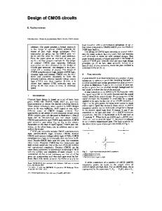
(a) (b) (c) Fig. 1: (a) Complete Model structure; (b) Wu ternary inverter [12]; (c) CM CompGate
Some of the possible choices of the five voltage levels we are dealing with are reported in Tab. 2 for a customised process (A, as obtained by Wu in [12]) and for a standard industrial process (B,C,D for the 1 µm ATMEL-ES2 process), where ∆VIL = VL + VTN - VI and ∆VIH = VI - VH - VTP are the voltage margins above and below VI that define the input voltage zones in which both p and n transistors are off and Nps is the number of supply voltage rails needed. It can be seen as in a non-customised process the voltage gaps are dramatically reduced and the number of supply voltage rails increased. This reduction of the voltage gaps is absolutely unacceptable for low-voltage applications. Choice A B C D
VDD 5 4 5 4
VSS 0 0 0 0
VH 3.3 3 4 2
VI 1.65 2 3 0.6
VL 0 1 2 0
VTP -1.9 -1.10 -1.31 -1.52
VTN 1.9 1.31 1.36 0.76
∆VIL 0.25 0.11 0.36 0.16
∆VIH 0.25 0.31 0.32 0.12
Nps 4 5 5 4
Tab. 2: Supply voltages and process parameters of the dynamic ternary gates defined in [12]
3. An innovative ternary logic design technique It is therefore necessary to find new multivalued models to obtain larger noise margins and better performance with a standard technology process. In such a
way, it would be possible to apply the low-power MVL asynchronous approach proposed in [4,5,6] also in low-voltage systems. Many efforts have thus been done to design dynamic ternary gates that use VDD and VSS as high and low logic level. In this section we introduce an innovative multiple-valued design technique called Complete Model Approach [13], to be used in the design of asynchronous elements; even if this methodology will be employed in this paper to design ternary logic, its straightforward generalisation applies for a nth base logic. The technique is based on the structure presented in Fig. 1a for ternary logic, generally called Complete Model structure or CM structure, in which there exists a path from each reference voltage (Vd, Vd/2 and gnd) to the output out. The paths are activated according to a set of two-valued functions fi which must respect the following rule stating that one and only one function is true at the same time:
∑n f n ( ∏ k ≠ n f k ) = 1 The CM structure thus acts as a binary-to-ternary interface that selects one and only one of the levels to be switched to the output and allows the full voltages to be used, without the need of body effect or threshold adjusted transistors. A dynamic complex gate (called CM CompGate) is presented in Fig. 1c: as it will be shown in the section 5, the CompGate can be used to realise an efficient bounded-delay asynchronous element. The CompGate uses a CM-like output structure, with a two-valued precharge signal pre and two ternary-valued input signals X and Y. Its logic function Z can be described by: 2 ⇔ Y > X ; Z = 1 ⇔ Y = X ; 0 ⇔ Y < X ;
If Y = 1 then the CompGate works like a ternary inverter, whereas if X = 1 it works like a ternary buffer. Thanks to this approach it is not necessary to modify the threshold voltages any more and only three reference voltages are needed.
4. Comparative simulations It is interesting to compare by simulation the CM structure and a traditional one, in particular to analyse the noise margins achieved by these two different approaches. The classical definition of noise margin [14] can be employed for binary CMOS gates with a transition zone where both NMOS and PMOS are conducting; it can not be applied to the ternary gates examined in this paper because they have not the transition zone. Furthermore, they are dynamic gates. Thus we have to define a new characterisation technique for dynamic multivalued gates to perform the comparison. Let us consider once more the STI ternary inverter defined in [12] and represented in Fig. 1b, and suppose to fix the period T of the signal pre. If we choose as the input X a linear ramp from VL to VH, the output Z will assume during the evaluation period values that depend on X, on T and on the input slope; in fact the inverter will charge the output load up to a value that depends on these factors. In that way we are able to calculate a "dynamic" characteristic that can be used to evaluate what a cascaded gate will have as input at the given operating frequency. We can also define something similar to the noise margin, measuring the points in which dY/dX=-1, being Y the envelope of Z. In a ternary gates we have four of such points labelled VIL, VIH, VILI, VIHI. So we can define four different noise margins: NML = VIL - VL, NMH = VH - VIH, NMIL = VILI - VI, NMIH = VI - VIHI. The simulations have been carried out using a 0.7 µm technology with nominal load, no optimisation of MOS dimension (W=1 µm and L=0.8 µm), a precharge signal of 50 MHz and a linear input signal with a slope of 5⋅106 V/s: for this gate we obtain the dynamic characteristic shows in Fig. 2a, where the intermediate voltage gaps are ∆VIL = 0.47 V, ∆VIH = 0.21 V, and the computed high and low noise margins are NMH = 0.44 V and NML = 0.22 V. The simulation performed on the CompGate of Fig. 1c shows that the circuit proposed in this paper has a larger swing than the STI: in fact, for the standard
inverter we have VH = 3 V, VI = 2 V and VL = 1 V and for the CM solution VH = 5 V, VI = 2.5 V and VL = 0 V, using the same power supplies VDD = 5 V and VSS = 0 V.
(b)
(a)
Fig. 2: Dynamic characteristics for (a) the STI and (b) the CompGate used as ternary inverter
Besides, the dynamic characteristic of the CM inverter (Fig. 2b) presents both wider intermediate voltage gaps and better noise margins: in fact, the CompGate is
characterised
by
∆VIL = 1.36 V,
∆VIH = 1.34 V,
NMH = 0.91 V
and
NML = 0.98 V. It is therefore possible to reduce the power supply voltage maintaining acceptable noise margins. It is also worth noting that the inverter of Fig. 1b behaves more critically than CM CompGate on the intermediate level because of charge sharing due to parasitic capacitance. 5. Design of asynchronous systems with CM approach Ternary logic may be extremely useful for asynchronous systems design: in fact, the intermediate level VI may be used as idle state so to distinguish two consecutive inputs with no need of a request line. In [4,5,6] a delay-insensitive model has been presented, in which no assumptions have been made nor on the internal or the external element delays. That model, even if it is the most general, it is more demanding than other asynchronous models as far as the internal functionality of the interface controller is concerned. A possible bounded-delay structure is described in Fig. 3a [13], where we have a Full Engine (FE) for communication, a Memory Unit (MU), which stores the
input data, and a Ternary Logic Unit (TLU) for data processing, in a way similar to that proposed in [4]. The correct handshake for this model is depicted in Fig. 3b: this protocol is in principle bounded-delay since we need to know the delay between the Fi activation and the return of In to the idle state. In
MU
dn
TLU
Out
In Vi Out
Vh Vi
Vi Vh
Vl Vi
Vl
Fi
FE
Fo Fo
Fi
(a)
(b)
Fig. 3: Ternary bounded-delay (a) model and (b) handshake.
The complete model may be used to design all the units: a possible implementation of the FE is presented in Fig. 4a, whereas a simple TSPC D flipflop [15] as MU and the CM structure of Fig. 1a as TLU have been used. The simulation of the FE and MU units has been carried out with nominal loads, no MOS optimisation and an average throughput of 30 MHz (Fig. 4b). The power dissipation of the FE is about 28 µW, and the total power is about 160 µW when a TSPC D flip-flop is used as MU. This value can be reduced to 57.2 µw if a lower power MU network is adopted [13]. Besides, these FE and MU networks have been successfully tested up to a throughput equal to 385 MHz without optimisation. As compared with the results obtained with the original ternary approach [4], the Complete Model asynchronous approach shows better speed performance with a comparable power consumption. However, it has to be taken into account that a less demanding asynchronous model (bounded-delay instead of delayinsensitive) has been used. Moreover, the evident improvements on the noise margins and on the number of supply rails obtained with the CM approach are counterbalanced by the hazard free and the easy design of the TLU permitted by the original ternary approach [4]. Finally, as compared with binary asynchronous
approach, the multivalued approach confirms its low-power behaviour, mainly due to the reduced voltage swing [4]. Vd Fi
/Fo D
Vd/2
Fo
(a)
(b)
Fig. 4: (a) Full Engine network and (b) simulation results of MU and FE units.
6. Conclusions Asynchronous circuits are an effective way to design low-power circuits; the increase of the routing area due to the need of a local handshaking can be recovered using a multiple-valued logic: it has been shown in [4,5,6] as very power efficient asynchronous circuits can be realised using a CMOS ternary logic that however drastically reduces the noise margins and increases the number of supply rails. A new CMOS ternary approach, the “complete model”, has been presented in this paper. If compared with the previously reported ternary solutions, the complete model shows wider voltage gaps and greater noise margins, so that the main drawbacks of the multivalued design are effectively counterbalanced using this approach. In that way it is shown that the low-power behaviour of asynchronous multivalued systems can be extended also toward future low-voltage applications.
References [1] S.Hauck, “Asynchronous Design Methodologies: An Overview”, Proc. IEEE, vol.83, no.1, pp. 69-93, Jan.1995. [2] K.C. Smith, “The prospects for multivalued logic: A technology and applications view”, IEEE Trans. Comput., vol. C-30, pp. 619-634, Sept. 1981. [3] S.L.Hurst, “Multivalued logic - Its status and its future”, IEEE Trans. Comput., vol. C-33, pp. 1160-1179, 1984. [4] R. Mariani, R. Roncella, R. Saletti, P. Terreni, “Delay-insensitive asynchronous circuits with CMOS ternary logic for low power applications”, Proc. of the 6th Int. Workshop on Power, Timing, Modeling, Optimization and Simulation PATMOS’96, Pitagora Editrice Bologna, pp.135-144, September 1996. [5] R.Mariani, R.Roncella, R.Saletti, P.Terreni, “On the Realisation of Delay-Insensitive Asynchronous Circuits with CMOS Ternary Logic”, Proc. of the 3th Int. Symp. on Asynchronous Circuits ASYNC’97, pp.54-62, Eindhoven, Apr. 1997. [6] R.Mariani, R.Roncella, R.Saletti, P.Terreni, “A Useful Application of CMOS Ternary Logic to the Realisation of Asynchronous Circuits ”, Proc. of the 29th Int. Symp. on Multiple-Valued Logic, ISMVL’97, pp.203-208, Antigonish, May 1997. [7] M. Yoeli, G. Rosenfeld, “Logical Design of ternary switching circuits ”, IEEE Trans. Comput., vol. C-14, pp. 19-29, Feb. 1965. [8] J.S. Wang, C.Y. Wu, M.K. Tsai, “Low power dynamic ternary logic”, Proc. IEE, vol. 135, pt. G, pp. 221-230, Dec. 1988. [9] P. Balla, A. Antoniou, “Low power dissipation MOS ternary logic family”, IEEE J. SolidState Circuits, vol. SC-19, pp. 739-749, 1984. [10] X. Wu, F. Prosser, “CMOS ternary logic circuits”, Proc. IEE - G, vol. 137, no. 1, pp. 2127, Feb. 1990. [11] K.W. Current, “Current mode CMOS multiple-valued logic circuits”, IEEE Journal of Solid-State Circuits, vol. 29, n. 2, pp. 95-107, 1994. [12] C.-Y. Wu, H.-Y. Huang, “Design and application of pipelined dynamic CMOS ternary logic and simple ternary differential logic”, IEEE Journal of Solid-State circuits, vol. 28, n. 8, pp.895-906, 1993. [13] F. Pessolano, “An innovative approach to the design of digital systems based on asynchronous logic”, Laurea Degree Thesis, (in italian) University of Pisa, February 1997. [14] N.H.E. Weste, K. Eshraghian, “Principles of CMOS VLSI Design - A system prespective”, Addison-Wesley, 1993. [15] J. Yuan, C. Svensson, “High-speed CMOS circuit technique”, IEEE Journal of SolidState Circuit, vol. 24, n. 1, pp.62-70, 1989.