A New Fast and Robust Stereo Matching Algorithm for Robotic Systems Masoud Samadi and Mohd Fauzi Othman Center for Artificial Intelligence and Robotics Universiti Teknologi Malaysia, Kuala Lumpur, Malaysia
[email protected],
[email protected]
Abstract. In this paper, we propose a new area-based stereo matching method by improving the classical Census transform. It is a difficult task to match corresponding points in two images taken by stereo cameras, mostly under variant illumination and non-ideal conditions. The classic Census nonparametric transform did some improvements in the accuracy of disparity map in these conditions but it also has some disadvantages. The results were not robust under different illumination, and because of the complexity the performance was not suitable for real-time robotic systems. In order to solve these problems, this paper presents an improved Census transform using Maximum intensity differences of the pixel placed in the center of a defined window and the pixels in the neighborhood to reduce complexity and obtain better performance and needs a smaller window size to obtain best accuracy compared to the Census transform. Experimental results show that the proposed method, achieves better efficiency in term of speed and robustness against illumination changes. Keywords: Census, Disparity Map, Robots, Robotic Systems, Stereo Vision, Stereo Matching.
1
Introduction
Most mobile robots are designed to operate under different circumstances. In order to perform their task, robots should have a sufficient realization of their environment to work safely within their workhouse [1]. 3D information of all objects in the field of view of the robot is essential for a reliable operation of autonomous vehicles. Classic sensors which are based on ultrasonic, laser, or time-of-flight, may generate 3D data, but they suffer from a low resolution and are high at cost. Nowadays, the fast development of robotics systems, using perception modules in different fields of autonomous robot operations like navigation [5], [6], visual servoing [7], or grasping [8] are became more important. Mobile robot systems, especially those which require fast and robust navigation methods are spread around the world. The main requirements for such a visual system are reliability and the rapid ability to convert images of a scene to 3D data to be used in the immediate and future reactions of the robot [4]. Stereo vision is a technology that uses two cameras which are horizontally aligned and mounted on a common baseline to estimate the depth of a field of view. Some of P. Meesad et al. (Eds.): IC2IT2013, AISC 209, pp. 281–290. DOI: 10.1007/978-3-642-37371-8_31 © Springer-Verlag Berlin Heidelberg 2013
282
M. Samadi and M.F. Othman
the most important advantages of this technique are high resolution and low cost. In addition, images taken by this method can be used for other applications too. As a result of this passive technology, it does not affect the operation area of the robot, thus it is an acceptable choice for home applications. However, due to the similarity, matching the corresponding points which had been collected by a pair of cameras is difficult to solve. Also, the environment conditions are not fixed and the illumination is always changing in the field of robot views, which leads to mismatching for many stereo matching algorithms [9]. In here we propose a method to overcome the mismatching problem in different lighting condition without losing the performance of the stereo matching algorithm in terms of speed and accuracy.
2
Related Works
In recent years, a lot of work has been done in the field of stereo matching techniques with researchers approaching many new stereo matching algorithms. These algorithms are evaluated and compared in the work of Hirschmuller in [12], [5]. Many matching algorithms just use the intensity value of a pixel to find the similarity between a pair of images. Since these methods depend directly on environment illumination, changes in the luminance will affect their results. The sum of squared differences (SSD) and the sum of absolute differences (SAD) [7] are two famous algorithms which work with a pixel intensity value. The correspondence feature in the second image should have the same value with the reference image. This assumption can be true only under ideal lightning conditions, which is hard to find in robotic application. In [8], Hannah proposed a slightly different method named normalized crosscorrelation (NCC). This algorithm reduced the effect of environment illumination changes on the result in the calculation of the images normalized intensity value. However NCC did not works directly with pixel values and it still had weakness regarding illumination [10]. The most different stereo matching algorithms are that presented by Zabih and Wodfile [11], which was a non-parametric local transform. These methods were very well-known Census and Rank transform, which look for a certain relations between image pixels in a defined window. These kind of nonparametric transforms have a good ability to reduce the effect of noises on images and achieve good results in various test conditions. Census transform obtains its result with a bit-wise calculation and compared to previous methods which only use one pixel value to perform the operation, has more efficient and accurate results and a great capability to be used in robotic systems because of its robustness to illumination changes. This particular feature makes Census efficient in different kinds of environments. Equations (1) and (2) explain the Census transform formula that uses intensity relation between the pixel in the center and neighbor pixels in a defined window size: ,
0 1
(1)
A New Fast and Robust Stereo Matching Algorithm for Robotic Systems
283
presents the pixel located in the center of the window and adjacent pixels are demonstrated by . If the intensity value of is more than its neighbor pixel the value of Census for that specific pixel will be 1 and if it is less than the neighbor pixel it will be 0 . The equation in (2) describes how the Census value for the center pixel of defined window is calculated: ,
,
,
,
(2)
Operator denotes a bit-wise concatenation, where is Census windows size and , are pixel coordinates.As mentioned before, the classic Census transformation has the ability to reduce noise and increase the performance of stereo matching algorithms in non-ideal lighting condition and different environments. One of the most important drawbacks in this method is the complexity of the algorithm which consumes a lot of system resources for computation. Then Zabih proposed the Sparse Census transform to reduce the calculation time. This method avoids the twice calculation for one pixel by defining a certain space to reduce the number of comparisons, although the formula is the same as normal Census. One of the best ways to decrease the computation time and solve the speed problem in robotic systems is changing the Census transform equation. In the next sections, our solution is explained and the test results are compared with existing methods.
3
An Improved Census Transform Stereo Matching Algorithm
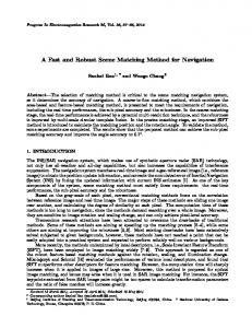
In order to increase the performance of Census method in terms of speed, without losing accuracy of the disparity map, we propose a novel method to achieve this goal. The workflow of the proposed method is demonstrated in Figure 1. As shown in the chart, at the very first stage of the procedure, the stereo images are captured from a pair of cameras which are vertically aligned. These cameras are calibrated before taking photos and the calibration values are saved in a matrix to use for future use. In the next step, images are going through undistortion function to correct the lens distortion and rectify them by using the calibration matrix that was mentioned in the previous stage. More explanation about image rectification and camera calibration can be found in [13]. Next, the pair of images is ready for further stereo matching process. In previous methods, the rectified images are transformed to an 8 bit images by means of the Census method before computing the initial three dimensional image. 3.1
Differential Transform
To reduce the computation cost and increase the speed performance of the Census transform, we changed the Census equation and detract the number of comparisons, so the complexity of the code is reduced and the program is executed with more speed than the old Census transform. Thus, in order to increase performance, we change the Census equation (1) to (3)
284
M. Samadi and M.F. Othman
|
,
|
(3)
The result of is the absolute differences between the center pixel of the Census window and the neighborhood pixels. The equation (2) is reformulated as shown in (4) ,
max
max
,
,
,
(4)
The determines the maximum differences between the pixel located in the center of the window and the neighbor pixels in a window with columns and rows. As the maximum intensity difference between two pixels in an image could be 255, thus the transformed matrix could be saved as an 8 bit image and does not depend on the window size. As a result of these changes, the execution speed of the code is increased and the resource consumed by the program is reduced, all these modification lead to computation the disparity map in less time compared to previous methods. 3.2
Stereo Matching
The results of the last step, so called Differential transform, are needed to produce the three-dimensional matrix. This matrix, which is called disparity space image (DSI), is generated with the size of . DSI is created by computing the hamming distance between the transformed images as shown in the formula: ,
,
,
,
(5)
DSI is computed when the right image is shifting horizontally from right to left (Figure 2), and the left image is used as the reference. The shifting distance is defined by in equation (5) and this value is called the disparity value. In fact, this is the furthest range which the stereo vision system can calculate. To achieve a better quality, we generate two different DSI. In the first, the left image is used as the reference, and in the second, the left image is used as the shifting and the right image is fixed. After computing the two DSI, the cost of aggregation is done on both DSI from the previous step. The cost aggregation is a method that sums the intensity values of pixels in a certain , window (6)
,
,
∑
∑
,
(6)
A New Fast and Robust Stereo Matching Algorithm for Robotic Systems
Stereo Camera
L
Rectification Undistortion
LRecti-
Differential Transform
RRecti-
LDiff RDif
DSI Calculation DSI
Left/Right Consistency
D D
WTA Subpixel
DSIL DSIR,
285
DSI
Cost Aggregation
DCons
Edge Normalization
DFinal
Disparity Map
Fig. 1. The workflow of the proposed algorithm
We then compare the aggregated value of different DSI layers to find the lowest value. When the lowest value is detected, it is seemed to be the best match for disparity in that specific region. This procedure will continue until all pixels in the image are checked. Thus, the initial disparity map is computed by using the winner take all method on the sum of the intensity value in a specific region in each DSI level (7). ,
min
,
, ,
(7)
After computing two initial disparity maps, with one left image acts as the reference and one right image as another reference, it is time to do a consistency check between and . This method will help to remove uncertain areas and occluded matches. In the final step noises are removed by a median filter and edges are normalized by dilate and blur steps.
4
Experiment Result
The proposed method, Census, Rank and Census Sparse have been tested on the Middlebury stereo vision dataset (Figure 3) and the results show that this method gained better execution speed compared to other methods. As a result of our experiments, it is clear that the proposed method needs a smaller window size to achieve the best accuracy in comparison to other algorithms. Thus, the executing speed of the algorithm increases and the time to calculate the disparity map reduces.
286
M. Samadi and M.F. Othman
d
v
ddmin min ddmin dmin dmin min
d dd ddd
Idiff Width* Idiff Height
u Fig. 2. The three-dimensional data called Disparity space image (DSI) in the size of disparities * image size
By our experiment and as mentioned in [2], [3] the best result of Census transforms are achieved with 16 16 window size, while the proposed algorithm can achieve the best accuracy with 5 5 window. This particular feature can reduce the large window size overload on the processor unit and decrease the calculation time. The time consumed by each method and the error rate of them are demonstrated in Table 1. Table 1. Speed and Accuracy Comparison on the Middlebury Dataset
Metrics
Dataset
Tsukuba Cones Time (s) Teddy Venus Average Tsukuba Cones Error Teddy (%) Venus Average
Proposed 0.00542 0.00803 0.00790 0.00732 0.00716 10.67 15.18 16.55 5.78 12.045
Methods Census Census Sparse 0.12891 0.02683 0.12891 0.07734 0.31196 0.08282 0.28534 0.08445 0.21378 0.06786 11.39 10.37 15.68 15.24 16.46 17.32 5.07 4.85 12.15 11.945
Rank Rank Sparse 0.07890 0.02846 0.17412 0.06475 0.16543 0.05402 0.08445 0.06348 0.12572 0.05267 11.99 12.19 16.22 15.32 16.74 17.02 6.22 5.69 12.7925 12.555
A New Fast and Robust R Stereo Matching Algorithm for Robotic Systems
287
Fig. 3. Comparison of the dissparity map for the Middlebury dataset (Cones, Teddy, Tsukuuba, Venus). From left to right (Fiirst row): Left Stereo image and its local ground truth dispaarity map, SAD, Census, (Second ro ow): Census Sparse, Rank, Rank Sparse, Proposed method.
288
M. Samadi and M.F.. Othman
Fig. 4. Comparison of disparitty map in different brightness and exposure for Middlebury ddataset (Cones, Teddy, Tsukuba, Venus). V From left to right SAD, Census Sparse, Rank, Propoosed method.
A New Fast and Robust Stereo Matching Algorithm for Robotic Systems
289
The proposed method also inherits some particular features of Census transform such as being robust to different luminance conditions, and has the ability to reduce effects of camera gain and bias, as shown in Figure 4.
5
Conclusion and Future Works
In this work, we deal with the stereo matching speed problem. Our research lies attention on non-parametric image transform methods to gain robustness of the stereo matching algorithm in different lighting conditions without losing the execution speed of the program. To achieve this goal we reformulate the old Census transform method and gained better performance in computing the disparity map compares to previous works. This method can be implementing in real-time stereo vision which is using in robotic applications. In future work, the proposed method will be implemented on a stereo vision-based robot which uses Intel x86 CPU architecture, the code already developed in C++ language under Visual Studio 2010 Environment therefore the program can be executed on the mentioned platform to analyze the robot behavior in a real world experiment. Acknowledgements. We would like to thank the Center for Artificial Intelligence and Robotics (CAIRO), Universiti Teknologi Malaysia (UTM) and Ministry of Higher Education (MOHE) for providing the research facilities. This research work has been supported the grant No. VOT 00G20.
References 1. Calderon, J., Obando, A., Jaimes, D.: Road Detection Algorithm for an Autonomous UGV Based on Monocular Vision. In: The Electronics, Robotics and Automotive Mechanics Conference, CERMA 2007, pp. 25–28 (September 2007) 2. Zinner, C., Humenberger, M., Ambrosch, K., Kubinger, W.: An Optimized SoftwareBased Implementation of a Census-Based Stereo Matching Algorithm. In: Bebis, G., Boyle, R., Parvin, B., Koracin, D., Remagnino, P., Porikli, F., Peters, J., Klosowski, J., Arns, L., Chun, Y.K., Rhyne, T.-M., Monroe, L. (eds.) ISVC 2008, Part I. LNCS, vol. 5358, pp. 216–227. Springer, Heidelberg (2008) 3. Weber, M., Humenberger, M., Kubinger, W.: A Very Fast Census-Based Stereo Matching Implementation on a Graphics Processing Unit. In: 2009 IEEE 12th International Conference on the Computer Vision Workshops (ICCV Workshops), September 27-October 4 (2009) 4. Grigorescu, S.M., Macesanu, G., Cocias, T.T., Dan, P., Moldoveanu, F.: Robust Camera Pose and Scene Structure Analysis for Service Robotics. Robotics and Autonomous Systems 59(11), 899–909 (2011) 5. Brown, M.Z., Burschka, D., Hager, G.D.: Advances in Computational Stereo. IEEE Transactions on Pattern Analysis and Machine Intelligence 25(8), 993–1008 (2003) 6. Scharstein, D., Szeliski, R.: A Taxonomy and Evaluation of Dense Two-Frame Stereo Correspondence Algorithms. Int. J. Comput. Vision 47(1-3) (2002)
290
M. Samadi and M.F. Othman
7. Kanade, T., Kano, H., Kimura, S., Yoshida, A., Oda, K.: Development of a Video-Rate Stereo Machine. Paper Presented at the Intelligent Robots and Systems 1995, Proceedings. 1995 IEEE/RSJ International Conference on Human Robot Interaction and Cooperative Robots, August 5-9 (1995) 8. Hannah, M.J.: Computer Matching of Areas in Stereo Images. Stanford University (1974) 9. Xin, L., Zhou, H., Yu, F., Li, X., Xue, B., Song, D.: A Robust Local Census-Based Stereo Matching Insensitive to Illumination Changes. In: 2012 International Conference on the Information and Automation, ICIA, June 6-8 (2012) 10. Murray, D., Little, J.J.: Using Real-Time Stereo Vision for Mobile Robot Navigation. Autonomous Robots 8(2) (2000) 11. Zabih, R., Woodfille, J.: Non-Parametric Local Transforms for Computing Visual Correspondence. In: Eklundh, J.-O. (ed.) ECCV 1994. LNCS, vol. 801, pp. 151–158. Springer, Heidelberg (1994) 12. Hirschmuller, H., Scharstein, D.: Evaluation of Stereo Matching Costs on Images with Radiometric Diferences. IEEE Transactions on Pattern Analysis and Machine Intelligence 31(9), 1582–1599 (2009) 13. Fusiello, A., Emanuele, T., Alessandro, V.: A Compact Algorithm for Rectication of Stereo Pairs. Mach. Vision Appl. 12(1), 16–22 (2000)