Jan 25, 2002 - section 2, homographies associated with scene planes between two images are discussed. The linear constraints on camera's intrinsic ...
ACCV2002: The 5th Asian Conference on Computer Vision, 23--25 January 2002, Melbourne, Australia.
A New Linear Camera Self-Calibration Technique Hua Li Huaifeng Zhang Fuchao Wu and Zhanyi Hu National Laboratory of Pattern Recognition, Institute of Automation, Chinese Academy of Sciences P.O. Box 2728, Beijing 100080, P.R. China Email:{hfzhang, fcwu, huzy}@nlpr.ia.ac.cn [22] improved Ma’s method. In their new method, rather than two sets of 3 mutually orthogonal motions, four sets of two orthogonal planar camera motions are used. In both Ma’s methods and Yang’s, only 4 intrinsic parameters of camera can be linearly determined. If a full perspective camera model is used, in other words, if the skew factor is non-zero, both of their methods become invalid. In this paper, we propose a new active vision based camera calibration technique which can compute all the 5 intrinsic parameters linearly. In our new method, the planar information in the scene is used, and the camera undergoes N (N>=2) sets of three mutually orthogonal motions or N (N>=5) sets of two orthogonal planar motions. The organization of the paper is as follows: In section 2, homographies associated with scene planes between two images are discussed. The linear constraints on camera’s intrinsic parameters and the uniqueness of solution with respect to configurations of camera motions are elaborated in section 3. A new camera calibration algorithm is outlined in section 4. The experiments on simulated images and real images are reported in section 5 and section 6 respectively. Finally some conclusions are given in section 7.
Abstract In this paper, a new active vision based camera self-calibration technique is proposed. The novelty of this new technique is that it can determine LINEARLY all the FIVE intrinsic parameters of a camera. The basic principle of our new calibration technique is to use the planar information in the scene and to control the camera to undergo several sets of orthogonal planar motions. Then, a set of linear constraints on the 5 intrinsic parameters is derived by means of planar homographies between images. In addition, the uniqueness of the calibration solution with respect to the configurations of the camera’s motion is also investigated. Keywords:
1
Camera Self-Calibration, Active Vision, Homography
Introduction
Camera calibration is an indispensable step to obtain 3D geometric information from 2D images. With the traditional calibration method, the camera’s intrinsic parameters are computed from projected images of a well structured object, called calibration grid. However, in many practical applications, a calibration grid is neither available nor desirable, thus people turned to a new paradigm, called ‘self-calibration’, i.e., calibration without calibration grid. Since the pioneer works in [1,2], many similar techniques have been reported in the literature [3-15]. However, almost all such techniques have to solve some nonlinear equations, which inevitably leads to either low computational speed or non-convergence. In order to overcome this difficulty, some researchers explored the possibility to constrain the camera to undergo some specially designed motions [16-22]. Ma [21] proposed an active vision based linear calibration method. In Ma’s method, two different sets of camera motions, each one of which consists of 3 mutually orthogonal translations, are used to linearly determine the camera’s intrinsic parameters. Yang et al.
2
Homography Associated with a Scene Plane Between Two Images
2.1
Camera Model
Here a full perspective camera model is assumed, then the camera intrinsic parameters matrix is
fu K = 0 0
s fv 0
u0 v 0 1
where (u 0 , v0 ) is the principal point, f u , f v the focal lengths in u and v axis respectively, s the skew-factor.
2.2 Homography of a Plane between Two Images
1
Assuming m = (u, v,1) T , m ′ = (u ′, v ′,1) T are the homogeneous coordinates of two corresponding points in two images. If these two corresponding points are projected from a same scene point lying on a plane π , the following relation holds:
With at least 4 pairs of corresponding points, H can be determined. If the camera undergoes pure translations, then from (3), there exists a unique factor σ such that: * tn T −1 H = σ (I + K K ) (4) d * tn T −1 H − σI = σK K (5) d * Because rank ( Ktn T K −1 ) = 1 , σ must be the solution of the following equations:
sm ′ = Hm (1) where matrix H is the homography between the two images induced by the plane π , and s an unknown non-zero factor. In other words, the homography is determined up to a non-zero scale factor. Now suppose the plane π in 3D space is defined * * as: n T x = d , where n is the unit normal vector of π , d the distance from the origin of the world coordinate system to plane π . Assume that the world coordinate system coincides with the first camera coordinate system, then for the first image, we have: λm = Kx Assuming the transformation from the first camera coordinate system to the second one is x ′ = Rx + t , the corresponding point in the second image can be expressed as: 1 * λ ′m ′ = Kx ′ = KRx + Kt = KRx + Ktn T x d * −1 tn T − 1 = λ ( KRK + K K )m d
det ( H − σI ) = 0 det ([ H − σ I ] ) [ H − σ I ] 2× 2 ∈ Ω ( H − σ I ) 2× 2 = 0,
(6)
(6) contains 6 linear equations about σ , so a unique solution can be obtained. A least squares solution of these 6 linear equations is used in practice.
3 3.1
Linear Constraints and Camera Motion Configurations Linear Constraints
If the camera undergoes two planar orthogonal translations t (1) , t ( 2 ) i.e. (t (1) ) T t ( 2 ) = 0 , assume that H 1 is the homography of a scene plane associated with the first translation, and H 2 is the homography of a scene plane (either the same plane as in the first translation, or another plane) associated with the second translation, then based on (3), we have: *T t (1) n1 H1 = σ 1 (I + K K −1 ) (7) d *T t (2) n 2 H 2 = σ 2 (I + K K −1 ) (8) d
From (1), the homography between these two images is: * tn T −1 H = σ ( KRK −1 + K K ) (2) d in (2), σ is an unknown non-zero factor. If the camera only undergoes a pure translation, the homography becomes: * tn T −1 H = σ (I + K K ) (3) d
2.3 Homography Calculation and the Associated Constant Factor Determination
so,
K −1 ( H 1 − σ 1 I ) K =
σ 1 (1) * T t n1 d
σ 2 (2) * T t n2 d Multiply (10) by the transpose of (9), then,
Since a homography can only be determined up to a scale, we can generally eliminate the scaling effect by assuming the homography has the following form:
K −1 ( H 2 − σ 2 I ) K =
h1 h 2 h3 H = h4 h5 h6 h h 1 8 7 Then H can be written as a column vector: h = (h1 , h2 , h3 , h4 , h5 , h6 , h7 , h8 ) T . From (1), a pair of corresponding points m = (u, v,1) T , m ′ = (u ′, v ′,1) T can bring out two linear constraints on h ,
(9) (10)
K −1 ( H 1T − σ 1 I ) K −T K −1 ( H 2 − σ 2 I ) K
=
Let
(u , v,1,0,0,0, u ′u, u ′v)h = u ′ (0,0,0, u , v,1, v ′u, v ′v)h = v ′
σ 1σ 2 * (1) T ( 2 ) * T n1 ( t ) t n2 = 0 3×3 d2
C=K
−T
K
−1
c1 = c2 c 3
c2 c4 c5
c3 c5 c 6
It is a symmetrical positive definite matrix. And the
2
following linear constraint on C can be derived since σ 1 , σ 2 can be obtained from H 1 , H 2 uniquely as shown in the preceding section.
words, the corresponding motion configuration is a degenerated one. Concerning the uniqueness of the solution of C for given five TPOTs, we have the following conjecture: Conjecture: Among the five motion planes, if no two or more planes are parallel, the matrix C can be determined uniquely modulo a scale factor.
( H 1T − σ 1 I )C ( H 2 − σ 2 I ) = 0 3×3 (11) is the fundamental constraint introduced in this paper. Let c = (c1 , c 2 , c 3 , c 4 , c 5 , c 6 ) T , (11) can be re-written as * A9×6 c = 09 (12) Although (12) contains 9 linear constraints on C, we can easily prove that only one constraint is useful, all the other constraints are dependent. In other words, matrix A is of rank one. Simple illation is as below: From (9) and (10), ( H 1T − σ 1 I ) and ( H 2 − σ 2 I ) are of rank one. So equation (11) can produce only one linear constraint on C. And we can conclude that (12) can also produce only one linear constraint on C . In order to uniquely obtain C in the sense of up to a scale factor, at least 5 constraints as defined in (12) are needed.
4
Suppose the camera observes a scene plane and the correspondence of image points is established beforehand, then our new self-calibration algorithm is as follows: (1) Control the camera to undergo N (N>=5) sets of two planar orthogonal translations (or N (N>=2) sets of three mutually orthogonal translations). (2) Compute
H i1 , H i 2
(4) Write the linear constraints on c in the form: * Ac = 0 9 . * (5) Compute the least squares solution for Ac = 09 . (6) Construct C , then decompose C −1 as: C −1 = VV T by Cholesky factorization, then decompose V as: V = KQ by RQ factorization, and finally normalize K to make k 33 = 1 . Then the normalized K is just the matrix of the camera’s intrinsic parameters.
5
Experiments with Simulated Images
As shown above, there are two factors which largely affect the performance of our algorithm. These two factors are noise level and the orthogonality of two camera translations within a same motion set. In order to assess their influences, the following experiments have been done.
i = 1,2
where H ij is the homography associated with the j th translation in the ith TMOT. Here, by “two sets of TMOTs being independent”, we mean that all the following 4×3 matrices must be of rank 3,
5.1 Noise Influence Here the size of simulated images is 1024*1024 pixels, and at each image point, a random noise is added. The camera’s setup is: f u = 1000, f v = 1000, s = 0.20, u 0 = 0, v 0 = 0 . Noise unit: pixel. 20 points are used for determining H . With different magnitude of random noise, the algorithm is run for 100 times, and then means and RMS errors of the intrinsic parameters are computed. The results are shown in Table1 and Table2. From these two tables, we know that with linear increases of noise level, RMS also increases linearly, which is quite satisfactory.
t j1 t k 2 t l 2 ] i, j, k , l = 1,2,3; i ≠ j, k ≠ l . In other words, 4 vectors ( t i1 , t j1 , t k 2 , t l 2 ) are not coplanar ones. i1
homographies
planar orthogonal translations. (3) Determine the scale factor σ i associated with each H i , as shown in section 2.
3.2.1 Two Sets of Three Mutually Orthogonal Translations (TMOT) Each pair of translations among the 3 translations in one TMOT can produce one constraint on C . So one TMOT can produce three constraints on C . Then at least 2 sets of TMOTs are needed to determine C . Concerning the uniqueness of the solution of C , we have the following proposition: Proposition : Γ i = {t i1 t i 2 t i 3 }, i = 1,2 are two sets of TMOTs, if these two sets are independent, then C can be determined uniquely modulo a scale factor from the following constraints:
[t
the
associated with the scene plane in each set of two
3.2 The Configurations of Camera Motions and the Uniqueness of Solution
( H i1 − σ i1 I ) T C ( H i 2 − σ i 2 I ) = 0 3×3 T ( H i 2 − σ i 2 I ) C ( H i 3 − σ i 3 I ) = 0 3×3 , (H − σ I )T C ( H − σ I ) = 0 i3 i1 i1 3×3 i3
Algorithm
T
Due to the limited space, the proof is omitted here. 3.2.2 Five Sets of Two Planar Orthogonal Translations (TPOT) As shown in the previous section, each set of TPOT can produce one linear constraint on C. Hence in general, 5 sets of TPOTs can produce 5 linear constraints on C. It is evident that in some cases, 5 TPOTs can not produce 5 independent linear constraints, in other
3
Table 1. Means of the estimated intrinsic parameters at different noise level Noise 0.1 0.2
fu
fv
s
u0
v0
999.620 999.524
999.705 999.627
0.535 -0.103
0.108 0.694
0.117 -0.164
0.3
997.178
998.711
-0.145
0.646
-2.838
0.4
1000.014
999.425
1.089
-0.521
0.972
0.6 0.8 1.0 1.5
997.965 999.079 996.211 1025.636
998.322 994.869 993.771 986.579
-0.965 1.826 -1.928 7.314
1.072 5.065 5.782 19.065
-2.249 7.403 4.021 65.364
92
87 | 93
86 | 94
Table 2. RMSs of the estimated intrinsic parameters at different noise level Noise
∆f u
∆f v
∆s
∆u 0
∆v 0
0.1 0.2 0.3
4.420 11.247 16.233
1.419 3.839 5.129
1.629 3.025 4.891
1.227 3.036 4.594
6.690 15.045 23.082
0.4
19.662
6.172
5.843
5.909
27.659
0.6 0.8
31.783 45.845
10.069 16.051
11.292 12.733
8.081 12.589
41.883 63.160
1.0 1.5
51.048 82.179
17.803 29.546
15.346 26.543
15.013 31.442
70.404 141.292
85 | 95
X-Y 89 | 91
The image size is: 1024*1024 pixels. The camera’s setup is: f u = 1000, f v = 1000, s = 0.20, u 0 = 0, v0 = 0 . In this case, image points do not contain any noise. But the included angle between the two camera translations is allowed to vary at random within a given error bound1. At each given error bound and for each given number of motion sets, 100 runs are done. The final results are shown in Table 3 and Table 4. In Table 3 and Table 4, “X-Y” stands for the included angle of the two translations for each planar motion set.
88 | 92
87 | 93
Table 3. Means of the estimated intrinsic parameters at different error bound
89 | 91 88 |
1
fu fv s u0 v0 fu fv
5 sets 976.234 1018.556 -14.591 -24.988 26.342 975.939 993.423
8 sets 1001.389 1000.040 -7.004 0.954 -1.387 999.004 998.746
10 sets 998.881 999.786 1.510 -3.237 0.668 1005.938 1006.312
-23.649 10.699 -21.761 972.576 994.415 -31.717 15.463 -3.369 944.180 1024.595 4.277 13.534 -55.905 928.851 1008.974 -54.663 -42.923 -10.703
-3.687 9.810 -1.292 995.750 1004.771 -5.566 5.320 -6.304 1000.055 1014.221 -17.269 31.311 -5.713 990.974 1039.206 -40.048 34.950 -13.128
-9.525 2.975 10.187 1024.539 1017.879 -19.352 3.799 17.905 1008.938 1009.758 2.719 -6.051 -2.246 1041.977 1038.543 -28.706 10.556 41.784
2.134 3.891 1.484 999.390 1004.243 -0.644 6.204 -1.356 1001.645 1017.907 -13.755 4.980 1.592 1019.730 1032.747 -27.762 21.341 13.602
Table 4. RMSs of the estimated intrinsic parameters at different error bound
5.2 Orthogonality Influence
X-Y
s u0 v0 fu fv s u0 v0 fu fv s u0 v0 fu fv s u0 v0
86
15 sets 998.661 1000.005 -0.893 -0.165 -0.808 1003.623 1003.812
| 94
85 | 95
Remember ideally the two translation should be orthogonal
4
∆f u ∆f v ∆s ∆u 0 ∆v0 ∆f u ∆f v ∆s ∆u 0 ∆v0 ∆f u ∆f v ∆s ∆u 0 ∆v0 ∆f u ∆f v ∆s ∆u 0 ∆v0 ∆f u ∆f v ∆s ∆u 0 ∆v0
5 sets
8 sets
10 sets
15 sets
68.675
22.476
14.833
12.223
95.449
20.111
15.430
12.137
89.769
24.096
15.750
12.298
79.402
20.059
17.572
11.282
93.204
23.037
15.660
12.774
76.504
36.093
28.332
24.695
74.637
36.193
33.237
19.735
76.964
40.716
34.825
25.863
76.272
37.052
36.785
29.878
96.948
44.650
32.760
27.553
116.353
56.076
51.361
33.932
117.717
54.311
42.966
37.355
137.267
69.961
49.458
40.116
124.863
63.049
41.249
36.142
131.662
69.823
50.069
33.646
134.559
74.162
62.798
42.071
157.014
77.104
61.539
54.406
157.637
93.322
66.006
58.155
147.420
101.423
77.876
58.146
181.170
88.721
81.984
51.644
146.971
82.832
88.394
64.677
193.981
100.698
87.937
77.262
186.325
111.342
104.461
68.707
199.289
98.310
106.240
81.448
163.040
99.643
94.143
78.437
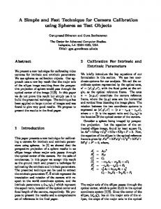
The highlighted points are the corresponding points selected from two planes which are orthogonal to each other. Fig 3 are the reconstructed planes with different view directions.
From these tables, we know that the more the number of the motion sets and the smaller the error bound, the better the estimated results. Hence in order to obtain satisfying results, if possible, the two camera translations within a same motion set should keep as orthogonal as possible and more images should be used. Fortunately, these two conditions can be generally satisfied in practice with an active vision system.
6
Experiments with Real Images
In real image experiments, a CCD camera is used. After the calibration, the calibrated intrinsic parameters are used to reconstruct a calibration grid to verify whether the calibrated parameters are reliable.
6.1
Fig 2: The two images used for the reconstruction
Calibrating the Intrinsic Parameters
Here a 3D scene including a plane is used. The camera undergoes 16 sets of two orthogonal translations, and we get 16 groups of images, each group contains 3 images (one image before translation, and two images after each translation). The image size is 384*288 pixels. One of the image groups is shown in Fig1.
(1)
(2) Fig 3: Reconstructed two planes with different view
Fig 1
In Fig 3, (1) is the top view, (2) is the side view. The included angle of the two reconstructed planes is 90.45 degrees, which is quite close to its real value of 90 degrees. Based on the fairly good reconstruction results, we can reasonably think that the calibrated intrinsic parameters are reliable. Besides, it is worth noting that the results from our linear calibration technique can be used as the initial values for a non-linear optimization method for further refining.
A group of images taken by a CCD camera
With our new algorithm, the calibrated intrinsic parameters of the CCD camera are listed in Table5.
Table 5.
The estimated intrinsic parameters
fu 524.6731
6.2
fv 256.9008
u0
v0
172.0141 190.6486
7. Conclusion
s -0.8220
In this paper a new active vision based self-calibration technique is proposed. Our new technique can LINEARLY determine all the FIVE intrinsic parameters. To our knowledge, in the literature there have been no method which can linearly calibrate a full perspective camera. The experiments with simulated data and real images validate our new camera calibration technique.
Verification via Reconstruction
Here a standard stereo vision technique is used to reconstruct the 3D scene to verify whether the calibrated intrinsic parameters are reliable. Fig 2 shows a pair of images used for the reconstruction of a calibration grid.
5
[10] M. Pollefeys, L. Van Gool, M. Proesmans, Euclidean 3D reconstruction from image sequences with variable focal lengths, in Proc. ECCV’96 [11] A. Shashua, Projective Structure from Uncalibrated Images: Structure From Motion and Recognition, IEEE-Trans. PAMI 16:8, pp.778-790, 1. [12] S. Avidan and A. Shashua, Threading fundamental matrices, in Proc. ECCV’98, Vol.-I, pp.124-140 [13] A. Heyden, A common framework for multiple view tensors, in Proc. ECCV’98, Vol.I, pp.3-19, 1998. [14] L. Quan and T. Kanade, Affine structure from line correspondences with uncalibrated affine cameras, IEEE-Trans. PAMI, Vol.19, No.8, pp.834-845, 1997. [15] B. Triggs, Autocalibration from planar scenes, in Proc. ECCV’98, pp.89-105, 1998 [16] L. Dron. Dynamic Camera Self-Calibration of from Controlled Motion Sequences, in Proc.CVPR’93, pp.501-506,1993. [17] A. Basu. Active Calibration: Alternative Strategy and Analysis, in Proc.CVPR’93, pp.405-500, 1993 [18] F. Du and M. Brady, Self-calibration of the Intrinsic Parameters of Cameras for Active Vision Systems, in Proc.CVPR’93, pp.477-482, 1993. [19] F. X. Li, Michael Brady, Charles Wiles, Fast Computation of the Fundamental Matrix for an Active Stereo Vision System, in Proc. ECCV’96, Vol-I. pp.156-166, 1996. [20] M. X. Li, Camera Calibration of a Head-Eye System for Active Vision, in Proc. ECCV’94, pp.543-554, 1994. [21] S. D. Ma, A self-calibration technique for active vision systems, IEEE Trans on Robotics and Automation, 12(1): pp.114-120, 1996. [22] C. J. Yang, W. Wang, and Z. Y. Hu, A active vision based self-calibration technique. Chinese Journal of Computers, Vol 5, pp.428-435, 1998.
Acknowledgments This work was supported by “973” Program (G1998030502) and the National Science Foundation of China (60033010, 69975021).
Reference [1] R. I. Hartley, Estimation of relative camera positions for uncalibrated cameras, in Proc. ECCV’92, pp.579-387, 1992. [2] O. D. Faugeras, What can be seen in three dimensions with an uncalibrated stereo rig, in Proc. ECCV’92, pp.563-578, 1992. [3] S. J. Maybank and O. D. Faugeras, A Theory of Self-Calibration of a Moving Camera, Inter. Journal of Computer Vision 8(2), pp.123-151, 1992. [4] Q. T. Luong and O. D. Faugeras, The Fundamental Matrix: Theory, Algorithms, and Stability Analysis, Inter. Journal of computer Vision 17, pp.43-75, 1996 [5] O. D. Faugeras et al., 3-D reconstruction of urban scenes from image sequences, Computer Vision and Image Understanding, Vol.69, No. 3, March pp.392-309, 1998. [6] R. I. Hartley, Self-Calibration of Stationary Cameras, Inter. Journal of Computer Vision 22(1), pp.5-23, 1997. [7] R. I. Hartley, Line and Points in three Views and the Trifocal Tensor, Inter. Journal of Computer Vision 22(2), pp.125-140, 1997. [8] R. Koch, M. Pollefeys, and L. Van Gool, Multi viewpoint stereo from uncalibrated video sequences, in Proc. ECCV’98, Vol.I, pp.55-71, 1998. [9] M. Pollefeys, R. Koch and L. Van Gool, Self-Calibration and Metric Reconstruction in spite of Varying and Unknown Internal Camera Parameters, in Proc. ICCV’98, pp.90-95, 1998.
6