A Novel Start-Up Scheme of Stator Flux Oriented Vector Induction Motor Drive Without Torque Jerk Tae-Won
Chun,
Meong-Kyu
* Bimal
Choi
K. Bose
* Dept. of Electrical Engineering, University of Tennessee 419 Ferris Hall, Knoxville, TN 37996-2100, U.S.A. e-mail :
[email protected]
Dept. of Electrical Engineering, University of Ulsan Mu-Gu-Dong, Nam-Gu, Ulsan, (Zip-code :680-749), KOREA e-mail :
[email protected]. ac.kr Abstract - The paper proposes a novel zero speed start-up scheme of a stator flux oriented vector-controlled induction motor drive without any torque jerk. A programmable 3-stage low pass falter (LPF) method is used for flux estimation. However, the torque jerk should be generated at the transition dne to the time delay of stator flux caused by 3-stage LPF. At standstill conditiow a method is derived to calculate a stator flux with only stator A feedforward control strategy of the stator flux is current. suggested to prevent the torque jerk during the transition from standstill mode to the vector control mode. Through experimental results with 32-bits DSP, the performance of the start-up scheme is verified.
I.
Controlled
INTRODUCTION
Recently, stator flux oriented vector controlled induction motor drive system is receiving wide attention in the literature [1]. The advantage of stator flux orientation is that it has less influence on parameter variation effect. The estimation of stator flux is only sensitive to the stator resistance variation which is easy to compensate. For the stator flux oriented vector control, the stator flux can be easily calculated from the machine terminal voltage and current as follows.
start the induction motor with indirect vector control and then switched to direct vector control when the motor speed begins to develop. But the implementation of this method is difficult and also large torque jump may occur during transition. In this paper, the standstill equations for estimating the stator flux at a zero speed are derived with current model of induction motor. The stator flux builds up to rated stator flux with the standstill equations, and then the drive transitions to the stator flux oriented vector control mode as the motor speed begins to develop. But the torque jerk should be generated at the transition due to the time delay of stator flux caused by 3-stage LPF. In order to prevent the torque jerk at the transition, the feedforward control of stator flux is suggested, which compensates for the time delay of stator flux. II.
DESCRIPTION
OF CONTROL
STSTEM
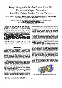
Fig. 1 shows the block diagram for a stator flux oriented vector controlled induction motor drive system with the start-up scheme.
The basic method for estimating the flux is by pure integration, in which the voltage measured noise, integration drift and parameter detuning effect can pose significant problems, especially at low frequency. To overcome the problems, some methods have been suggested. The sensors of voltage and current are calibrated every time the system is started [2]. A low-pass filter is substituted for the pure integral, where the gain of filter is adjusted with stator frequency [3,4]. But the methods suggested by the above papers are insufficient to solve the problems. A programmable 3-stage low pass filter (LPF) method proposed at paper [5] is used for flux estimation in this study. Although the programmable 3-stage LPF gets ideal integration at any frequency, there are two problems. One problem is that the drive is not self-starting, and the another problem is that the LPF causes time delay of stator flux at transient condition, especially at low frequency. The paper [6] has proposed to
. W Standstill
Equation v; .,.
Id,
s
IQ
~
n...
V;k
u
k
. ..- .. . ...-1... ib rrogrammarue #. II < 3- stage >V. . HI f’ COe
Fig. 1 Block diagram of stator flux oriented vector control system with start-up scheme.
0-7803-7116-X/01/$10.00 (C) 2001 IEEE
148
/’~
,
I
The torque control and stator flux control are used in the outer loop. In the standstill (SS) mode, stator flux signals are obtained from the standstill equation and the stator flux establishes to the rated value before applying the torque command.
When
the
synchronous
speed CO. reaches
a
threshold value (I& as motor speed begins to develop, the drive is switched to the stator flux oriented vector control (SVC) mode, where the programmable 3-stage LPF is used for stator flux estimation. And also, as the machine stops (zero speed) in SVC mode, the operation is switched back to SS mode. At transition from SS mode to SVC mode, some torque jerk may be generated if there are some mismatching with two modes during the transitions. The magnitude of stator flux, synchronous speed and angle, torque are calculated with stator flux and stator current at 2-axis stationary reference fi-ame. III.
STANDSTILL
MODE
OF INDUCTION
The stator flux linkages can be expressed in terms of the rotor flux linkage and stator current as follows.
MOTOR
The induction motor is started with current model of induction machine, and the standstill equation from current model will be derived to build up the stator flux to the rated flux at a zero speed. From the rotor voltage equations at 2-axis stationary reference frame, the d- and q- axis rotor flux linkages can be obtained as follows.
(lo) (where
LO = (L,L, - L~)/L,.)
Through from (7) to (1 O), d- and q-axis stator flux can be calculated with only stator currents. IV.
PROGRAMMABLE
3-STAGE
CASCADED
LPF
The programmable 3-stage LPF is used to calculate stator flux in stator flux oriented vector control system [5], and Fig.2 shows the block diagram for implementing programmable 3stage LPF.
-. R.ij,
-4 –
+ E,: ~-($~
E,; ~-($~
Ez LPF1 z-$~
LPF1 z-()~
~ds_Ol
LPF2 1-$ ~
vq%_ol
LPF2 +($d
VQL02
~ds-02
LPF3 .+
LPF3 Z-@d vm_03
~ds_03
( where TV= RF/ L, : rotor time constant)
G,
The stator and rotor flux linkages are expressed as
% Fig. 2 Block diagram for implementing
As the LPF performs integration
G,
v:, programmable
3-stage LPF.
of a sinusoidal signal, the
output signal of LPF lags phase 90° with attenuating as l/a& The signal voltages behind the stator resistance drop are integrated within the cascaded low-pass filter estimation block. This block essentially consists of three identical programmable low-pass filters with the phase shift of @d= ((T/2) - r$A)/ 3 cO, = O
per stage at any frequency, where q+ is the phase shift of the
into (1) and (2), the rotor flux linkage can be expressed as stator current.
analog hardware filter. The time constant of 3-stage LPF, and the compensation gain (G3) is programmable as a fnnction of frequency so as to get ideal integration at any frequency.
As the machine is at standstill,
after substituting
The frequency dependent phase lag (+ with time constant (7)
Tk for the analog hardware filter are
(8)
(11)
149
becomes the output of LPF3, and the output of LPF2 leads
The time constant T and phase shift ~d for each programm-
phase r#d with multiplying
able LPF are expressed as
~-
with respect of output
of LPF3, and also the output of LPF 1 leads phase 2@d with
‘=;tan[+oh}]
(12)
multiplying
with respect of output of LPF3. The 7 [1+ (’roe)] three outputs of LPF are assigned to the initial values of each LPF in the feedforward control, and Fig.3 and Fig.4 show
(13)
~d = -+~ -3 tan-’(me,
,where synchronous speed (D. can be calculated with stator
waveforms for v:,
and y:,
and initial
values of k.tage
LPF
respectively.
current and voltage, and stator flux [2]. At the programmable 3-stage LPF shown in Fig.2, the output of each LPF lags phase ~d and attenuates as 1 /~-
with respect of the input of each LPF,
The
compensation gain G, can be derived as
G,
=+k+(wzl[l+(uBJ’T
(14)
e
V.
FEEDFORWAED
CONTROL
OF STATOR
FLUX
When the drive is transitioned to SVC mode, firstly the initial values of 3-stage LPF are determined with d- and q-axis stator flux calculated in SS mode, and then the programmable 3-stage LPF is applied to calculate the stator flux. The programmable 3-stage LPF gives compensation for frequency dependent phase shift and gain by the hardware filter, and so it However, the gets ideal integration at any frequency.
Fig. 3 Waveforms for I&
and initial values of LPF.
programmable 3-stage LPF causes the time delay of stator flux at the transient conditions, and so the stator flux decreases rapidly at the transition to SVC mode, and then the stator flux reduction generates some jerk of motor torque at the start-up. The feedforward control of stator flux is suggested to compensate for time delay of stator flux, and so it prevents the torque jerk at the transition to SVC mode. If the difference between the reference (rated) stator flux and the actual stator flux is greater than the tolerant limit (E) at transient state, the stator flux establishes to reference stator flux by adjusting the initial values of 3-stage LPF. At the feedforward control of stator flux, the three initial values of LPF in Fig.2 are calculated in the reverse direction from reference stator flux
I
I
0
60
240
180
am
*M
& [Deg]
Fig. 4 Waveforms for ~~,
and initial values of LPF.
The initial values of d-axis stator flux LPF can be derived respectively.
v:. Firstly, d-axis and q-axis stator flux can be written as
s ~ds_03
= ~
direction (16), the previous gain G,
150
* = $Cosee
s
As the outputs of each LPF are derived in reverse from the d- and q- axis stator flux shown in (15) and input of LPF should be obtained from the output of LPF, The stator flux divided by the correction
120
(17)
Correspondingly, the initial values of q-axis stator flux LPF can be derived respectively.
(20)
Yg
0.4
Y.
0.2
1.
SS Mode
o
SVC Mode
4
.*
vqs.02
=
%+@e)2Sin(@.+@d)
(21)
~
s
Yqs.ol
(22)
-~/msin(Oe+2#3d) – ~ s
VI. A. Simulation
SIMULSION
AND EXPERIMENTAL
RESULTS
‘“”s] ‘“~
results
4s;
0,
Digital simulation is carried out to verify the performance of the feed forward control of stator flux. Fig.5 and Fig.6 show the start-up response without and with the feed forward control of stator flux respectively. In the SS mode, d-axis stator flux builds up to rated stator flux, while the q-axis stator flux remains O. When the stator flux establishes to rated flux, torque command is applied. As the synchronous speed reaches a
[Desl
300 150 “ “0
0.3
0.6
Fig. 6 Start-up response with feedforward
B. Experimental
threshold value (at =5 rad/s), the drive is switched to SVC mode. As shown in Fig.5, at the instant of transitioning to SVC mode, the stator flux decreases so rapidly due to the time delay of stator flux, and then increases slowly to rated flux. As the stator flux decreases so rapidly, the torque jerk is generated during the transition. As shown in Fig.6, the stator flux is kept constant with the feed forward control, and so there is no torque jerk during transitioning to SVC mode. L
SS Mode
1,5
1,2
control.
Results
Fig.7 shows the block diagram of hardware configuration.
D
~
SVC Mode
9
0,9
Time [see]
----F] 12-bit AID
Torque Cent rol System
‘1
L,–*,
DSP TMS320C30
Fig. 7
I I
System hardware configuration
The current regulated PWM IGBT inverter and 3 HP induction motor are available for experiments. The parameters of induction motor are given in Table. 1. Table 1. Parameters of induction motor Stator resistance
45: ee
300
[DL%l ! 50
.“ . 0
0.3
0.6
0.9
1.2
1.5
Time [see] Fig. 5 Start-up response without feedforward
control.
151
Rotor resistance Stator inductance Rotor inductance
Rs = Rr = Ls = Lr =
0.686 [Q] 0.646 [Q] 83.9 [mH] 85.3 [mH]
Mutual inductance
Lm = 81.4 [mH]
Moment of inertia Pole
J = 0.0376 [Kgm2] P=4
The control system is implemented with 32-bit TMS320C30 operating with a clock frequency of 33MHz and the sampling interval is 200w for speed and stator flux control. A space voltage algorithm is used for maximum utilization of dc link voltage, The dc link voltage, stator voltage and stator current are sensed by isolation devices and 12-bit A/D converters. The dc motor driven by de-to-de converter is used for controlling the load torque of induction motor Fig.8 shows experimental results for stator flux and current at SS mode. The d-axis stator flux builds up to rated flux (0.39 Wb.) by d-axis stator current while q-axis stator flux and current remain 0, After 0.5sec, the d-axis stator flux reaches the rated flux.
Time (0.5 skiiv.)
i&
(a) torque [1.5 Nm/div], stator flux [0.065 Wb/div], synchronous speed [25 radls /div]
r 00 .
t I I
i~,
I J n
00
h
r
I
, . ,
T!me (0.2 sldw )
,
,
I
)
~qs
(a) d-q axis stator current [ 1 A/dw]
0.0 s
‘f’&
0.0—
- /
r
#-
“
k
““
I I
1
I
1
!
NIT)
I
I
I
I
I
(b) d-&
I
I
I
I
q-axis stator flux [0.13 Wb/div]
Fig. 9 Start-up response without feedforward
Y;,
0.0
I
Time (0.5 s/div.)
1.
+
h
Time (0.2 s/div.) (b) d-q axis stator flux [0.13 Wb/div] Fig. 8 Stator current and flux responses at SS mode.
Fig.9 and Fig. 10 show the experimental results without and with the feedforward control of stator flux respectively at the torque command of 8 N.m, As shown in Fig.9, at the instant of transitioning to SVC mode as the synchronous speed reaches a threshold value (5 rad/s), the stator flux decreases so rapidly and then the torque jerk is generated. As shown in Fig. 10, the stator flux remains constant with the feedforward control, and so induction motor starts smoothly without torque jerk during the transitioning to SVC mode.
152
control
J
constant for estimating stator flux is used to solve the problem of integration at low speed. In order to prevent the torque jerk at the transition, the feedforward control of stator flux is suggested, which compensates for time delay of stator flux at transient state. It was shown that the induction motor starts smoothly without torque .- ierk through both simulation and experimental results,
y: 0.0
I
I
I
I
I
I
1
1
!
1
I
I
I
I
I
I
I
I
I
I
I
[
y$ 0.0
L
REFERENCES
I
I
I
I
I
I
I
I
I
[1] Xingyi Xu, Rik De Doncker, and D.W.Novotny, “A stator flux oriented induction machine drive”, Conf. Rec. of PESC, 1988, pp.870-876. [2] Xingyi Xu, and D. W.Novotny, “Implementation of direct statnr flux
I
Time (0.5 sktiv.) (b) d-&
q-axis stator flux [0.13 Wb/div]
Fig. 10 Start-up response with feedforward control. [3]
VII.
CONCLUSION
[4]
In this paper, a novel start-up scheme for stator flux oriented vector controlled induction motor drive is presented, where ac machine starts at zero speed in the SS mode, and transitions to vector control mode as the speed begins to develop. At a zero speed, the method to calculate the stator flux with only stator currents is derived. The 3-stage LPF with programmable time
[5]
[6]
153
orientation control on a versatile DSP based system”, IEEE Trans. on Ind. AppL, VOL27, No.4, July/Aug., 1991, PP.694-700. K. H.Hurst, T.G.Habetler, G. Griva, and F. Profumo, “Zero-speed tacho-less LM. torque control : simple a matter of statnr voltage integration”, Conf. Rec. of IEEE-APEC, 1997, pp.749-753. M.R.Zolghadri, C.Pelisson, and D. Roge, “Stsrt up of global direct torque control system”, Conf. Rec. of PESC, 1996, pp.370-374. B. K.Bose, and N. R.Patel, “A programmable cascaded low-pass filter based flux synthesis for a stator flux oriented vector controlled induction motor drive”, IEEE Trans. On Ind. Elec., VOL44, No. 1, Feb., 1997, pp. 140-143. B.K,Bose, M.G,Simoes, D. R. Crecelius, K.Rajaahekara, and R.Martin, “Speed sensorless hybrid vector controlled induction motor drive”, IEEEIAS Annual Meeting, 1995, pp. 137-143.