IEEE TRANSACTIONS ON POWER ELECTRONICS, VOL. 23, NO. 2, MARCH 2008
941
Stator Flux Vector Control of Induction Motor Drive in the Field Weakening Region Michele Mengoni, Luca Zarri, Member, IEEE, Angelo Tani, Giovanni Serra, Senior Member, IEEE, and Domenico Casadei, Senior Member, IEEE
Abstract—A torque control scheme that utilizes the stator flux components as control variables, applied to a speed-sensorless induction motor drive, is presented. The proposed scheme allows the motor to exploit the maximum torque capability in the whole speed range, and shows a reduced dependence on the motor parameters. It is based on a control algorithm that decreases the d-component of the stator flux as soon as the voltage corresponding to the maximum torque exceeds the available voltage. The control scheme produces a smooth transition into and out of the field weakening region and preserves the torque dynamic. The feasibility of the field weakening technique is confirmed by computer simulations and experimental tests. Index Terms—AC motor drives, torque control, variable speed drives, velocity control, traction motor drives.
I. INTRODUCTION
W
HEN the induction motors are used for applications at high speed, it is desirable to retain the maximum torque capability in the field weakening region. The torque capability of an induction motor is limited by the maximum current and the maximum voltage that the inverter can apply to the motor. Several papers were presented in order to achieve the maximum torque capability of the machine over the whole field weakening region [1]–[4]. According to these field weakening algorithms, the optimal flux value of the motor should be updated by means of look-up tables or explicit expressions containing the motor parameters and quantities such as the motor speed, the motor currents, the dc-link voltage and the requested torque. However, the performance of these algorithms is strictly related to the accuracy by which the parameters are known. A further problem is represented by the variable value of the leakage and magnetizing inductances, to which the rotor-fluxoriented scheme is particularly sensitive [5]. In addition, the drive performance in the high speed range may depend on the correct determination of the base speed, which is function of the actual dc-link voltage and the overload capability. As a consequence, new methods for compensating the parameter variations and the uncertainties of the models have been investigated. Among these, some adaptive schemes have been
Manuscript received March 16, 2007; revised July 4, 2007. This paper was presented at APEC’07, Anaheim, CA, February 25–March 5, 2007. Recommended for publication by Associate Editor J. Ojo. The authors are with the Department of Electrical Engineering, University of Bologna, Bologna 40136, Italy (e-mail:
[email protected]). Color versions of one or more of the figures in this paper are available online at http://ieeexplore.ieee.org. Digital Object Identifier 10.1109/TPEL.2007.915636
proposed in order to provide a suitable estimation of the varying parameters [6]–[8]. These methods provide good drive performance to the detriment of the complexity of the control scheme and the regulator tuning. For the reasons stated above, the stator-flux-oriented drive, more insensitive to parameter variations than the rotor-flux-oriented one, has received an increasing attention for field weakening applications [9]–[11]. In particular, [10] presents a robust method for field weakening operation of DTC induction motor drives where the flux reference is adjusted on the basis of the torque error behavior. In fact, a suitable method for robust field weakening is to determine the optimal flux level using closed-loop schemes that analyze the motor behavior, rather than look-up tables or explicit expressions containing the motor parameters. From this point of view, interesting contributions towards robust field weakening strategies were proposed in [12], [13] for stator-flux-oriented induction motor drives and in [14]–[18] for rotor-flux-oriented induction motor drives. According to these papers, the flux is adjusted on the basis of the supply voltage requested by the regulators. If this voltage is greater than the available one, the field weakening algorithm reduces the flux. Furthermore, employing a suitable voltage control strategy allows the motor to exploit the maximum torque in the whole speed range. The traditional field-oriented control utilizes the stator current components as control variables. The d-component of the stator current acts on the rotor flux, whereas the q-component is proportional to the motor torque. As the control of the motor flux is obtained indirectly by controlling the motor currents, the algorithm presented in [14] for achieving the maximum torque is rather complex, requiring the tuning of several PI regulators (two PI regulators are used for the current regulation, two PI regulators for the field weakening and another one for the speed regulation). The stator-flux field oriented control presented in [13], similarly, uses the same number of PI regulators. This makes difficult to obtain an optimal motor behavior, especially for drives with low inertia. In this paper, a novel field weakening scheme for induction motor drives is presented. In the proposed rotor-flux-oriented control scheme the main control variables are the stator flux components instead of the stator current components. This basic choice simplifies the control scheme, exhibits a fast torque response [19] and reduces the number of PI regulators. In addition, the proposed scheme allows the motor to exploit the maximum torque capability in the whole speed range. The feasibility of the field weakening technique is confirmed through simulations and experimental tests.
0885-8993/$25.00 © 2008 IEEE
942
IEEE TRANSACTIONS ON POWER ELECTRONICS, VOL. 23, NO. 2, MARCH 2008
II. MACHINE EQUATIONS The behavior of the induction machine can be described in terms of space vectors by the following equations written in a reference frame synchronous with the rotor flux: (1) (2) (3) (4)
III. MAXIMUM TORQUE CAPABILITY IN THE FIELD WEAKENING REGION In the high-speed range the motor performance is limited by the maximum inverter voltage, the inverter current rating and the machine thermal rating. that the inverter The maximum voltage magnitude can apply to the machine is related to the dc-link voltage and the modulation strategy. Using Space Vector Modulation (SVM) the maximum magnitude of the stator voltage vector is (16)
(5) where is the pole pairs number, is the angular speed of the is the rotor angular speed in electric rarotor flux vector, dians, and “ ” denotes the scalar product. Solving (3) and (4) with respect to and , and substituting in (2) and (5) yields
(6) (7) where the parameter
is defined as follows: (8)
The reference frame orientation is chosen so that the d-axis has the direction of the rotor flux vector. Hence (6) can be rewritten in terms of d and q components as follows: (9) (10) Also (7) can be rewritten as (11) As can be seen, these equations are quite similar to the corresponding equations of the traditional field oriented control based on d–q stator current components. In fact the rotor flux depends , whereas the motor torque is proportional to . only on In steady-state operation, (1), (3), and (9) become (12) (13) (14) (15) These steady-state equations will be utilized for the analysis of the maximum torque capability.
The voltage limit and the current limit can be represented by the following inequalities: (17) (18) Inequalities (17) and (18) sensibly influence the motor behavior, especially at high speed. It is known that the operation of an induction motor can be divided into three speed ranges, namely the low speed range (region I), the constant-power speed range (region II) and the decreasing-power speed range (region III). In region I, the current limit and the rated flux level determine the operating point corresponding to the maximum torque. The beginning of region II is defined as the voltage required . In region II, it is to inject the maximum current reaches necessary to reduce the stator flux magnitude to keep the back emf approximately constant. Therefore the operating point corresponding to the maximum torque requires a rotor flux magnitude lower than the rated one, and the magnitudes of the stator current vector and stator voltage vector are equal to the and , respectively. As the torque is limit values inversely proportional to the rotor speed, the power delivered to the load is nearly constant. Finally, in region III the available dc-link voltage is not sufficient to inject the maximum current and the power delivered to the load decreases nearly proportionally with the rotor speed. It is evident that the maximum torque capability is a consequence of the voltage and current limits. In order to determine the operating point corresponding to the , it maximum torque, when the stator voltage is equal to is opportune to introduce the angle between the stator flux vector and the rotor flux vector, as follows: (19) (20) Combining (11), (15), (19) and (20), it is possible to express the motor torque as (21) At high speed, the voltage drop on the stator resistance is small and (12) can be approximated as (22)
MENGONI et al.: STATOR FLUX VECTOR CONTROL OF INDUCTION MOTOR DRIVE
943
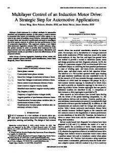
Fig. 1. Block diagram of the torque control scheme, including the field weakening strategy.
Combining (22) and (21) leads to the following expression of the torque in the high speed region:
(23) From (23) it is clear that for any value of , the maximum torque is produced when the angle between the stator flux and is equal to . the rotor flux vector is 45 , i.e., However, when the maximum torque is delivered to the load, . In fact, according to the current could be greater than (13) and (14), the stator current components are related to the corresponding stator flux components. Since the magnitude of the stator current vector must not ex, a limitation strategy should ceed the maximum current from reaching too be present to prevent the flux request high values. is the d-component of the current corresponding to the If , in order to guarantee that the current limit (18) is satflux cannot be greater than the folisfied, the absolute value of lowing value: (24) As a consequence, due to (14), the flux component be greater than the following limit value:
cannot
(25) In conclusion, the maximum torque compatible with the constraints (17) and (18) is given in any operating condition by the : following value of (26) This fundamental relationship will be used by the field weakening algorithm to achieve the maximum torque operation.
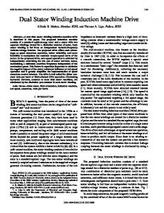
Fig. 2. Limitation block (b) for the q-component of the stator flux vector.
IV. CONTROL ALGORITHM The torque control block diagram, including the proposed field weakening strategy, is shown in Fig. 1. It is worth noting that the subscript “req” in Fig. 1 is used for the output quantities of the regulators, whereas the subscript “ref” denotes the reference signals at the input of the regulation loops. The control scheme is implemented in a reference frame synchronous with the rotor flux vector, like traditional field oriented , controls. It is assumed that a suitable observer estimates and the angular frequency of the rotor flux vector. A. Torque Control The motor torque is controlled by comparing the torque reference with the estimated torque . On the basis of the torque error, the PI regulator (a) produces a torque request by adjusting the q-component of the stator flux, according to (11). Therefore, if the reference torque is higher than the actual torque, the PI , otherwise it tends to regulator (a) tends to increase the decrease it. B. Control of Rotor and Stator Fluxes The rotor flux is controlled by adjusting the d-component of the stator flux, according to (9). In region I, the d-component of the stator flux is constant . At higher speeds, instead, it and has the rated value
944
IEEE TRANSACTIONS ON POWER ELECTRONICS, VOL. 23, NO. 2, MARCH 2008
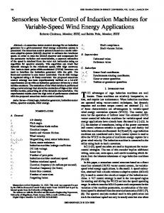
Fig. 3. Block diagram of the field weakening controller based on the saturation of the voltage regulator.
is reduced by the field weakening algorithm, as described in Section V. The stator flux regulator behaves as a proportional controller, with some additional terms compensating the stator back-EMF and the voltage drop caused by the stator resistance. The stator flux regulator equation can be expressed as follows: (27) where 1/ represents the gain of the controller. , leads to the folCombining (27) and (1), i.e., lowing equation, expressing the dynamic behavior of the stator flux vector: (28) According to (28), in order to obtain fast flux transients, and consequently a high torque dynamic, it is necessary to adopt small values of . The limitation block (d) ensures that the voltage reference satisfies the voltage constraint (17), namely the voltage reference . vector lies inside a circle with radius The behavior of the limitation block (d) is described by the following equation: (29) According to (29), if the requested voltage is greater than the limitation block (d) performs a proportional reduction of its magnitude, but preserves the angular phase. Finally, the reference voltage vector in the stator reference , where is the frame is calculated by means of the operator phase angle of the rotor flux vector with respect to the stationary reference frame. C. Maximum Torque Capability In order to guarantee the maximum torque capability, the flux given by (26). This task is request has to be lower than performed by the limitation block (b), shown in details in Fig. 2. for usual overload At low speed this block does not limit conditions. It is interesting to note that, at high speed, the limitation block (b) prevents instability phenomena by limiting the torque reference (i.e., ) to values lower than the maximum achievable
Fig. 4. Limitation block (f) for the d-component component of the stator flux vector.
torque, according to (26). In fact, without the limitation block (b), an excessive torque request causes an increase of the reand quested voltage, which in turn yields to a reduction of of the produced torque. This behavior proceeds leading to a progressive reduction of the stator flux until the motor stops. V. FIELD WEAKENING ALGORITHM Several field weakening strategies are possible for induction motor drives, as reported in the introduction. However, the best results are obtained using closed-loop controllers based on the principle of reducing the flux reference as soon as the voltage request becomes greater than the available voltage. This principle can be implemented according to the block diagram shown in Fig. 3. As can be seen, the stator flux regulator compares the flux reference with the corresponding estimated value and establishes the voltage that has to be applied to the motor. When the motor operating point is very close to the field weakening region, the voltage request may become greater . A negative difference between the than the limit voltage of the requested voltage limit voltage and the amplitude means that the back-emf is too high and the flux level should be reduced. This task is performed by the PI regulator (e), that . If this difference is integrates the difference negative, the flux request decreases; otherwise, the flux level increases up to the rated value defined in the limitation block (f). Fig. 4 shows the behavior of the limitation block (f) in details, and are the maximum and the minimum where admissible values of the d-component of the stator flux, respectively. It is worth noting that in the field weakening region, owing to the integral part of the regulator (e), the amplitude of the voltage request tends to equal the limit voltage. From this point of view, the field weakening control scheme is very similar to
MENGONI et al.: STATOR FLUX VECTOR CONTROL OF INDUCTION MOTOR DRIVE
an anti-windup scheme preventing a voltage request greater than the available voltage. Although the scheme of Fig. 3 allows the motor to fully utilize the supply voltage, it has an inherent drawback related to the fact that fast variations of the torque demand in region II and III lead to undesired flux transients which delay the torque response. In so that the voltage fact this scheme is based on selecting required to produce the demanded torque satisfies the voltage limit. For example, if a torque reduction is required in region II or III, the control system correspondingly reduces the requested is forced to reach a voltage, and as a consequence also new steady-state value, thus causing undesired transients of the rotor flux. To avoid this problem, the scheme of Fig. 3 should be modified in order to change the basic principle for the selection of the flux level. It is widely known that, if the motor operates at constant speed, fast torque responses can be achieved only if the control scheme keeps the flux level constant during the torque transients. In particular, the flux level should be always set to the value required to generate the maximum achievable torque at any operating speed. In this way any demand of torque variations within the admissible values is achieved without changing but only . This new field weakening strategy is implemented as shown in Fig. 1. For a given value of the d-component of the stator flux, and consequently of the rotor flux, the maximum torque is achieved . when Taking this equation into account, the voltage required to generate the maximum torque can be determined from (27) as follows:
(30)
945
the subscript “s” will be used to identify quantities expressed in the stator reference frame. The stator flux is determined integrating the stator voltage (34) The rotor flux can be estimated as (35) The phase angle of the rotor flux vector, necessary for the field oriented control, can be derived from (35) as (36) It is evident from (34) that the estimation of the stator flux vector can be affected by stator resistance mismatch, sensor offsets and the inverter non-linearity (inverter dead-times, voltage drop on the conducting switches, etc.). However, at high speed, and hence in the field weakening region, the estimation error is lower than that at low speed, because the input voltage becomes the most prominent term in the right-hand side of (34). The estimation error on the phase angle depends on the stator flux estimation error, the mismatch on the leakage inducand the offset of the current sensors. The leakage intance ductance shows moderate variations with the stator currents and it will be assumed practically constant. In conclusion, the stator flux observer depends only on two and , but the effects of machine parameters, namely this dependence can be considered negligible in the high speed range. On the contrary, in order to obtain good performance at low speed, it is preferable to adopt a closed-loop flux estimator, that could reduce the effect of parameter mismatch and sensor offsets [4], [20], [21].
(31)
B. Estimation of the Angular Frequency of the Rotor Flux Vector The angular frequency needed in (27) and (33) is obtained by means of the following equation:
(32)
(37)
is the corresponding angular frequency of the rotor and flux, expressed by
The angular frequency is insensitive to disturbance and noise that usually affect the stator flux and the stator currents, owing to the filtering action applied to the rotor flux. When this action is not adequate, an additional low-pass filter can be applied to (37).
where
is defined as
(33) It is worth noting that in practical applications it is possible to approximate with and therefore the knowledge of the rotor parameters is not necessary. The main advantage of the proposed field weakening scheme is the independence from the base speed and a fast torque response in the field weakening region. VI. FLUX AND TORQUE OBSERVERS A. Flux Observer The aim of the flux observer is the determination of stator flux and phase angle of the rotor flux, which are necessary for the field oriented control of the induction machine. The flux observer operates in the stator reference frame. In the following
C. Torque Observer The torque can be estimated from the measurements of the stator current and the estimation of the stator flux, as follows: (38) As can be seen, the torque estimation does not require explicitly any motor parameters, excepts the pole pairs. VII. OVER-CURRENT LIMITATION DURING THE MAGNETIZING TRANSIENT The use of flux components as control variables is very similar to that of the traditional vector control based on the regula-
946
IEEE TRANSACTIONS ON POWER ELECTRONICS, VOL. 23, NO. 2, MARCH 2008
TABLE I MOTOR PARAMETERS
tion of the stator currents. However, a little attention should be paid during the start-up transient, because the stator flux reference cannot change too quickly, in order to avoid over-currents. as folIt is possible to come to this conclusion by expressing lows: (39) Equation (39), obtained combining the d-component of (3) and (4), shows that the d-component of the stator current is limited by the magnitude of the rotor flux. Before the motor start-up, the rotor flux magnitude is zero and a sudden stator flux request could cause very high magnetizing currents. within the This behavior can be prevented by limiting following upper bound: (40) in (40) is not necessary. In fact, taking The knowledge of (35) into account, (40) becomes as follows: (41) In conclusion, to avoid over-currents, it is sufficient that the upper bound of the limitation block shown in Fig. 4 is calculated as follows: (42) where is the rated flux and is given by (41). This solution allows keeping the current within the safe limit value. Finally, it is worth noting that, once again, the only motor . parameter that has been used is VIII. SIMULATION RESULTS Preliminarily, some numerical simulations have been carried out to confirm the effectiveness of the field weakening strategy. The motor parameters are reported in Table I, and the load is supposed to be only inertial. To compare the simulation results with the experimental results, which will be shown in the next section, the operating conditions of the simulations are the same of the real test bench. In particular, the input voltage is 50% of the rated voltage, so leading to a base speed of about 700 rpm. Fig. 5 shows the motor behavior in response to a 25 Nm step command of the motor torque (the figure does not include the end of the transient). Vertical dash-dotted lines delimit the three regions of operation of the induction motor. Initially, the torque delivered to the load is zero, the motor is at standstill and the
Fig. 5. Computer simulation. Starting transient from 0% up to 700% of the base speed after a torque step of 25 Nm. Main motor quantities. 1) Torque reference. . 4) ' . 5) V . 6) V . 7) Stator 2) Estimated torque. 3) ' current. 8) Motor speed.
stator flux corresponds to the rated value. As the torque command is applied, the motor starts up. The q-component of the stator flux requested by the PI regulator (a) is limited to the , corresponding to a stator current equal to . value reaches the voltage limit, the field weakAs soon as ening algorithm decreases the d-component of the stator flux. As a consequence of the reduction of the magnetizing current, , the q-component of the stator current, proportional to increases, making it possible to keep the stator current equal to the limit current in region II. As soon as the motor enters in region III, the current decreases and the maximum value of is set equal to . The small oscillations superimposed on the torque waveform, i.e., track (2), are due to two main causes. The first one is unavoidable and consists in the switching operation of the converter. In fact the amplitude of the current ripple is almost independent of the motor speed, whereas the currents decrease as the speed decreases. Hence, the torque ripple is more evident in the high speed range, when the torque delivered to the load is small. The second cause is the non-optimal tuning of the regulators. In fact, the main motor regulators are usually tuned with reference to the operation corresponding to the rated load and speed. Their behavior is not optimal in the field-weakening region, thus leading to a system response which is not completely dumped. However, these issues are not due to the particular structure of the proposed control scheme, but are inherent in field-weakening applications. Further details on the controller tuning can be found in [22]. Fig. 6 shows the motor behavior after a torque reduction from 25 Nm to 5 Nm in region II. As can be seen, immediately after the torque decreases, the voltage delivered to the load is lower , but this voltage margin does not mean that than should increase. In fact, the motor continues accelerating and decreases without unwanted transients. This behavior could not be achieved without changing the basic scheme of the field weakening strategy of Fig. 3 as proposed in Fig. 1.
MENGONI et al.: STATOR FLUX VECTOR CONTROL OF INDUCTION MOTOR DRIVE
Fig. 6. Computer simulation. Torque reduction from 25 Nm to 5 Nm in region II during an acceleration transient. Main motor quantities. 1) Torque reference . 4) ' . 5) V . 6) V . 6’) V . 2) Estimated torque. 3) ' 7) Stator current. 8) Motor speed.
Fig. 7. Experimental test. Starting transient from 0% up to 700% of the base speed. Main motor quantities. 1) Estimated torque (10 Nm/div). 2) ' (0.20 Wb/div). 3) ' (0.20 Wb/div). Stator current (20 A/div).
IX. EXPERIMENTAL RESULTS A complete drive system has been realized to verify the feasibility of the proposed control scheme. The experimental set-up consists of an IGBT inverter and a 4 kW, four-pole squirrel cage induction motor. The motor parameters are the same ones reported in Table I. The test motor is coupled to a separately excited dc machine, 18.4 kW, 3000 rpm. The control algorithm is implemented on a Digital Signal Processor (DSP) TMS320C28. The cycle period of the control scheme, including the field weakening algorithm, is 100 s. Some tests have been carried out to investigate the drive performance in the field weakening region. In order to limit the test bench speed to safe values, the motor has been fed with a reduced voltage, i.e., 50% of the rated voltage, so leading to a rated speed of about 700 rpm. Fig. 7 shows the motor behavior during a transient from 0% up to 700% of the rated speed (the figure does not include the
947
020
+20
Fig. 8. Experimental test. Torque reversal from Nm to Nm starting from 70% of the base speed. 1) Estimated torque (20 Nm/div). 2) Speed (0.20 Wb/div). 4) Stator current (20 A/div). (700 rpm/div). 3) '
Fig. 9. Experimental test. Torque variation in region II from 20 Nm to 5 Nm during an acceleration transient. Main motor quantities. 1) Estimated torque (0.20 Wb/div). 3) (20 Nm/div). 1’) Torque command (20 Nm/div). 2) ' (0.20 Wb/div). 4) Stator current (20 A/div). '
end of the transient) after a torque step of 20 Nm. As can be seen, the motor behaves as expected, namely the current is constant in region II and decreases in region III. The experimental results are in good agreement with the computer simulations shown , constant in region I, slightly inin Fig. 5. In particular creases in region II, keeping the stator current equal to the limit value. Some tests were carried out to assess the dynamic performance of the motor drive. In Fig. 8, the motor behavior in region I during a torque reversal from 20 Nm to 20 Nm is shown. As can be seen, the dynamic behavior of the motor is not affected by the field weakening algorithm and a fast torque response is achieved. As regards the motor behavior at low speed, the control system exhibits a good performance during the transients, even when the motor goes across the zero-speed point, provided
948
IEEE TRANSACTIONS ON POWER ELECTRONICS, VOL. 23, NO. 2, MARCH 2008
deceleration transient. Fig. 10 shows the motor behavior when the speed decreases from about 600% to 80% of the base speed. The deceleration is obtained by increasing the breaking torque generated by the dc machine operating as a load. It can be verified that, as the speed decreases, the control algorithm up to the rated increases smoothly the flux reference value. Finally, Fig. 11 shows the motor behavior during the magincreases netizing transient. It can be seen that the current rapidly to establish the rated flux and never reaches unsafe value, thus preventing the onset of over-currents. X. CONCLUSION
Fig. 10. Experimental test. Deceleration transient from 600% to 80% of the base speed. Main motor quantities. 1) Estimated torque (20 Nm/div). 2) ' (0.20 Wb/div). 3) ' (0.20 Wb/div). 4) Stator current (20 A/div).
A control strategy for field weakening operation of speed-sensorless induction motor drives is analyzed in this paper. The control system scheme utilizes the stator flux components as control variables and decreases the d-component of the stator flux as soon as the voltage corresponding to the maximum torque achievable at a given speed tends to exceed the maximum voltage. The control scheme allows a smooth transition into and out of the field weakening mode, exploiting the maximum torque capability of the machine over the whole operating speed range. The main advantages of proposed field weakening algorithm are: 1) reduced dependence on machine parameters, 2) no need of calculation of the base speed, which in general depends on the machine parameters, motor current and dc-link voltage, and 3) fast torque response, also in the field weakening region. The effectiveness of the proposed control scheme has been verified by computer simulations and experimental tests. REFERENCES
Fig. 11. Experimental test. Start-up transient. Main motor quantities. 1) ' (0.20 Wb/div). 2) ' (0.20 Wb/div). 3) i (20 Nm/div). 4) i (20 Nm/div).
that the crossing transient is fast enough. In steady state operation, instead, the motor frequency can be reduced up to 5% of the rated frequency without degradation of the system stability. Fig. 9 shows the motor behavior in region II after a step variation of the torque command from 20 Nm to 5 Nm during an acceleration transient. As can be seen, the behavior of the motor is not affected by the is similar to that of Fig. 6, namely torque transient. In response to the torque variation only changes and consequently the stator current amplitude shows a corresponding reduction. The torque behavior shown in Fig. 9 can be justified as follows. During the acceleration transient, the motor enters region II. Although the torque command is constant, the d-component of the stator flux and the torque delivered to the load decrease due to the action of the field-weakening regulator. After a fast variation of the torque reference, the actual torque follows the new value and remains constant until the maximum achievable torque is greater than the torque command. The torque starts decreasing again as soon as the torque command cannot be satisfied at the current speed. Afterwards, some tests have been carried out to evaluate the capability of the control system to increase the flux during a
[1] X. Xu and D. W. Novotny, “Selection of the flux reference for induction machine drives in the field weakening region,” IEEE Trans. Ind. Appl., vol. 28, no. 6, pp. 1353–1358, Nov./Dec. 1992. [2] S. H. Kim and S. K. Sul, “Maximum torque control of an induction machine in the field weakening region,” IEEE Trans. Ind. Appl., vol. 31, no. 4, pp. 787–794, Jul./Aug. 1995. [3] G. Griva, F. Profumo, M. Abrate, A. Tenconi, and D. Berruti, “Wide speed range DTC drive performance with new flux weakening control,” in Proc. PESC’98 Conf., Fukuoka, Japan, May 17–22, 1998, vol. 2, pp. 1599–1604. [4] D. Casadei, F. Profumo, G. Serra, A. Tani, and L. Zarri, “Performance analysis of a speed-sensorless induction motor drive based on a constant-switching-frequency DTC scheme,” IEEE Trans. Ind. Appl., vol. 39, no. 2, pp. 476–484, Mar./Apr. 2003. [5] H. Grotstollen and J. Wiesing, “Torque capability and control of a saturated induction motor over a wide range of flux weakening,” IEEE Trans. Ind. Electron., vol. 42, no. 4, pp. 374–381, Aug. 1995. [6] R. J. Kerkman, T. M. Rowan, and D. Leggate, “Indirect field-oriented control of an induction motor in the field-weakening region,” IEEE Trans. Ind. Appl., vol. 28, no. 4, pp. 850–857, Jul./Aug. 1992. [7] E. Levi and M. Wang, “A speed estimator for high performance sensorless control of induction motors in the field weakening region,” IEEE Trans. Power Electron., vol. 17, no. 3, pp. 365–378, May 2002. [8] M. S. Huang, “Improved field-weakening control for IFO induction motor,” IEEE Trans. Aerosp. Electron. Syst., vol. 39, no. 2, pp. 647–658, Apr. 2003. [9] M. H. Shin, D. S. Hyun, and S. B. Cho, “Maximum torque control of stator-flux-oriented induction machine drive in the field-weakening region,” IEEE Trans. Ind. Appl., vol. 38, no. 1, pp. 117–121, Jan./Feb. 2002. [10] D. Casadei, G. Serra, A. Tani, and L. Zarri, “A Robust method for flux weakening operation of DTC induction motor drive with on-line estimation of the break-down torque,” in Proc. EPE’05, Sep. 11–14, 2005, pp. 1–10.
MENGONI et al.: STATOR FLUX VECTOR CONTROL OF INDUCTION MOTOR DRIVE
[11] T. S. Kwon, M. H. Shin, and D. S. Hyun, “Speed sensorless stator fluxoriented control of induction motor in the field weakening region using Luenberger observer,” IEEE Trans. Power Electron., vol. 20, no. 4, pp. 864–869, Jul. 2005. [12] A. Biinte, H. Grotstollen, and P. Krafka, “Field weakening of induction motors in a very wide region with regard to parameter uncertainties,” in Proc. PESC’96, Jun. 26–27, 96, vol. 1, pp. 944–950. [13] H. Abu-Rub, H. Schmirgel, and J. Holtz, “Sensorless control of induction motors for maximum steady-state torque and fast dynamics at field weakening,” presented at the IAS’06, Tampa, FL, Oct. 8–12, 2006. [14] S. H. Kim and S. K. Sul, “Voltage control strategy for maximum torque operation of an in-duction machine in the field weakening region,” IEEE Trans. Ind. Electron., vol. 44, no. 4, pp. 512–518, Aug. 1997. [15] L. Harnefors, K. Pietiläainen, and L. Gertmar, “Torque-maximizing field-weakening control: Design, analysis, and parameter selection,” IEEE Trans. Ind. Electron., vol. 48, no. 1, pp. 117–122, Feb. 2001. [16] F. Briz, A. Diez, M. W. Degner, and R. D. Lorenz, “Current and flux regulation in field-weakening operation,” IEEE Trans. Ind. Appl., vol. 37, no. 1, pp. 42–50, Jan./Feb. 2001. [17] D. Casadei, G. Serra, A. Tani, and L. Zarri, “Robust flux weakening operation of induction motor drives based on stator flux vector control,” in Proc. Int. Conf. Elect. Machines (ICEM’06), Chania, Greece, Sep. 2–5, 2006, pp. 489/1–489/6. [18] D. Casadei, G. Serra, A. Tani, and L. Zarri, “A robust method for field weakening operation of induction motor drives with maximum torque capability,” in Proc. IAS’06, Tampa, FL, Oct. 8–12, 2006, vol. 1, pp. 111–117. [19] A. Tripathi, A. M. Khambadkone, and S. K. Panda, “Dynamic control of torque in overmodulation and in the field weakening region,” IEEE Trans. Pow. Electron., vol. 21, no. 4, pp. 1091–1098, Jul. 2006. [20] C. Lascu, I. Boldea, and F. Blaabjerg, “Comparative study of adaptive and inherently sensorless observers for variable-speed induction-motor drives,” IEEE Trans Ind. Electron., vol. 53, no. 1, pp. 57–65, Feb. 2006. [21] C. Lascu, I. Boldea, and F. Blaabjerg, “Very-low-speed variable-structure control of sensorless induction machine drives without signal injection,” IEEE Trans Ind. Appl., vol. 41, no. 2, pp. 591–598, Mar./Apr. 2005. [22] F. Blaabjerg, M. P. Kazmierkowski, M. Zelechowski, D. Swierczynski, and W. Kolomyjski, “Design and comparison of direct torque control techniques for induction motors,” in Proc. EPE’05, Dresden, Germany, Sep. 11–14, 2005, pp. 1–9. Michele Mengoni was born in Forli, Italy, in 1981. He received the electrical engineering degree (with honors) from the University of Bologna, Bologna, Italy, in 2006 where he is currently pursuing the Ph.D. degree. His research interests include sensorless control of induction motors, multiphase drives and ac/ac matrix converters.
Luca Zarri (M’06) was born in Bologna, Italy, in 1972. He received the M.Sc. degree (with honors) and the Ph.D. degree in electrical engineering from the University of Bologna, Bologna, Italy, in 1998 and 2007, respectively. He was a Plant Designer with an Italian engineering company until 2002. In 2003, he became a Laboratory Engineer for the Department of Electrical Engineering, University of Bologna, with which he had collaborated since 1998. Currently, he is an Assistant Professor and his scientific work is related to electrical drives and power electronics. His research interests include ac–ac matrix converters, multilevel converter and sensorless control of induction motors. Dr. Zarri is a member of the IEEE Industry Applications, IEEE Power Electronics, and IEEE Industrial Electronics Societies. He is a Registered Professional Engineer in Italy.
949
Angelo Tani was born in Faenza, Italy, in 1963. He received the “Laurea” degree (with honors) in electrical engineering from the University of Bologna, Bologna, Italy, in 1988. He joined the Department of Electrical Engineering, University of Bologna, in 1990, where he is currently an Associate Professor. His scientific work is related to electrical machines and drives, power electronics, and Maglevs. He has authored more than 90 papers published in technical journals and conference proceedings. His current activities include ac/ac matrix converters and direct torque control of induction motors.
Giovanni Serra (SM’04) was born in Bologna, Italy, in 1950. He received the Ph.D. degree (with honors) in electrical engineering from the University of Bologna, Bologna, Italy, in 1975. Following service in the Italian Army, he joined the Department of Electrical Engineering, University of Bologna, first as a recipient of a Fellowship of the Consiglio Nazionale delle Ricerche, then as a Research Associate, and, since 1987, as an Associate Professor. He is currently Professor of Electrical Machines in the Department of Electrical Engineering. He has authored more than 120 papers published in technical journals and conference proceedings. His fields of interests are electrical machines, electrical drives, and power electronic converters. His current activities include direct torque control of ac machines, linear motors, and ac–ac matrix converters. Dr. Serra is a member of the IEEE Industry Applications and IEEE Dielectrics and Electrical Insulation Societies and the Italian Electrotechnical and Electronic Association (AEI). He is a Registered Professional Engineer in Italy.
Domenico Casadei (SM’04) received the “Laurea” degree (with honors) in electrical engineering from the University of Bologna, Bologna, Italy, in 1974. He joined the Electrical Engineering Department, University of Bologna, in 1975. He is currently Professor of Electrical Drives. His scientific work is related to electrical machines and drives, linear motors, and power electronics. Since 1994, he has been a member of the International Editorial Board of the International Journal of Electromotion. He has published extensively in technical journals and conference proceedings. His present research interests include direct torque control of induction motors, brushless motors, matrix converters, and power quality. Dr. Casadei is a member of the IEEE Industrial Electronics and IEEE Power Electronics Societies and the Italian Electrotechnical and Electronic Association (AEI). He is a Registered Professional Engineer in Italy.