cessors of the ICL-DAP3. Therefore, all element operations. (componentwise XOR) within one row operation have been parallelized, permitting execution of a ...
A Parallel Hardware Architecture for fast Gaussian Elimination over GF(2) A. Bogdanov, M.C. Mertens, C. Paar, J. Pelzl, A. Rupp Horst G¨ortz Institute for IT Security, Ruhr University Bochum, Germany {bogdanov,mertens,cpaar,pelzl,arupp}@crypto.rub.de
Abstract
solved accurately, approximative solutions using fast iterative algorithms are simply useless. Another kind of LSEs - which we primarily address in this paper - appears in the cryptanalysis of certain classes of symmetric ciphers. Here, large numbers of medium-sized1 LSEs over GF(2) must be solved extremely fast to enable practical attacks. Software implementations of existing algorithms have proven to be too slow for this task. However, to the best of our knowledge the alternative of an efficient implementation in hardware has not been analyzed thoroughly yet. In this paper we show that there is still room for drastic efficiency improvements of current algorithms when targeting special purpose hardware such as re-programmable logic. In order to develop such a special purpose hardware architecture we analyzed the suitability of various algorithms while taking possible simplifications over GF(2) into account. Gaussian elimination turned out to be basically best suited for hardware implementation due to its simplicity. Moreover, the coefficient matrices of LSEs are not required to have any special properties like being symmetric positive definite2 as this is the case for example for the conjugate gradient methods [12]. However, compared to software, a direct implementation of Gaussian elimination in hardware does not yield the desired advantage in efficiency. By slightly modifying the logic of the algorithm and parallelizing element and row operations, we were able to develop a highly efficient architecture for solving medium-sized LSEs and computing inverse matrices. In a similar way, an architecture for fast matrix multiplication can be obtained and can possibly be used in conjunction with the other architecture to solve large LSEs by means of Strassen’s algorithm [16]. This paper is roughly structured as follows. We start with a brief discussion of previous work in this area. After reviewing standard Gaussian elimination with backward substitution, we present our optimized version of the algorithm for hardware implementation and analyze its performance. After that, further applications of the hardware architecture are discussed including its particular suitability in the area of cryptanalysis. We then present the actual design of the hardware architecture for solving medium-sized LSEs. Finally, we describe our proof-of-concept implementation on a contemporary low-cost FPGA and provide estimates for a possible ASIC implementation.
This paper presents a new variant of the well-known Gaussian elimination for solving linear systems of equations (LSEs) over GF(2) and its highly efficient implementation in hardware. The proposed hardware architecture can solve any regular and (uniquely solvable) overdetermined LSE and is not limited to matrices of a certain structure. Its average running time for n×n matrices with uniformly distributed entries equals 2n (clock cycles) as opposed to about 41 n3 in software. Moreover, the average running time remains very close to 2n for random matrices with densities much greater or lower than 0.5. Our architecture has a worst-case time complexity of O(n2 ) and also a space complexity of O(n2 ). With these characteristics the architecture is particularly suited to efficiently solve medium-sized LSEs as they frequently appear in, e.g., cryptanalysis of stream ciphers. Besides solving LSEs over GF(2), the architecture at hand can also accomplish the computation of matrix inversion extremely fast. Using a similar architecture, matrix-by-matrix multiplication can be done in linear time and quadratic space. Thus, these architectures can possibly be used as building blocks of a more complex architecture for solving large LSEs by means of Strassen’s algorithm. We realized our architecture for solving medium-sized LSEs on a contemporary low-cost FPGA. The implementation for a 50 × 50 LSE can be clocked with a frequency of up to 300 MHz and computes the solution in 0.33µs on average.
1. Introduction Solving linear systems of equations is a very common computational problem appearing in numerous research disciplines. From a complexity theoretical point of view, the solution of an LSE is efficiently computable , i.e., using for example the well-known Gaussian elimination algorithm any LSE can be solved in at most cubic time. However, for some areas current algorithms and their software implementations are insufficient or unsatisfying in practice. This is often due to the large dimension or number of LSEs that must be solved in order to accomplish a specific task. For instance, this is the case in the cryptanalysis of asymmetric encryption schemes like RSA or ElGamal, where very large but sparse LSEs over GF(2) or GF(p) (p prime) need to be solved to obtain a secret key. Since these LSEs must be
216 LSEs with 656 variables for the A5/2 cipher used in GSM. AT = A and xT Ax > 0 for all non-zero vectors x.
1 E.g., 2 I.e.,
1
2. Previous Work
• An element in the i-th row and j-th column of a matrix A is denoted by aij .
The special case of efficiently using Gaussian elimination for LSEs with binary coefficients is not well documented yet. To the best of our knowledge, no previous work covers the particular topic of improving time efficiency by implementing an optimized, highly parallelized variant of Gaussian elimination in hardware. All research done until now deals with parallelized implementations of the standard algorithm for Gaussian elimination without altering the algorithm itself. Furthermore, there is almost no performance data available. In [5], Gaussian elimination for binary coefficient matrices is implemented as part of the DARPA HPCS Discrete Mathematics Benchmark. However, since the author’s focus was on a different part (pattern matching) of the benchmark, there is no explicit performance data for solving LSEs given. In [15], an implementation of Gaussian elimination over GF(2) is described for the ICL-DAP. The limit is a matrix containing 4096 × 4096 elements according to the 4096 processors of the ICL-DAP3 . Therefore, all element operations (componentwise XOR) within one row operation have been parallelized, permitting execution of a row operation within one clock cycle which results in an overall quadratic time complexity. The need for a supercomputer makes this solution quite expensive, while the achieved grade of parallelization with special purpose hardware is still not as high as possible. The most recent work describes an implementation of an adapted algorithm for LU-decomposition on an NVidia GeForce 7800 GPU which is able to solve a 3500 × 3500 matrix with 32bit real number coefficients in approximately 5 seconds, where the asymptotic time complexity is still cubic [10]. This impressively shows the power of non-x86 hardware, the cost (around $500 for a GeForce 7800 GTX based graphics card at the time of writing) and time complexity are not yet optimal, though. Further work in the field of solving LSEs is done for very large, but sparse matrices with implementations of the Wiedemann or Lanczos algorithm which both exploit the sparsity of the matrix [14, 11]. For matrices of dimensions up to a magnitude of 103 the overhead introduced by these advanced algorithms more than compensates their better (O(n)) time complexity. Since our focus is on medium sized and preferably not sparse matrices, the given references follow a different approach which is not considered in this work.
• Column vectors are denoted by lowercase letters, e.g. v, while a row vector is denoted by ~v = v T .
4. Mathematical Background There are basically two flavors of the Gauß algorithm (both having cubic complexity in time) which are usually used synonymously in literature. In this paper, we will differentiate between Gaussian elimination and LU-decomposition, though. Preliminaries: Any LSE with its coefficient matrix in lower (upper) triangular shape can trivially be solved by forward (backward) substitution. For a given LSE of the form A · x = b, LU-decomposition decomposes the coefficient matrix A into the product of a lower triangular matrix L and an upper triangular matrix U : L · U · x = b. The solution is obtained by first solving the problem L · y = b for y, where y = U · x and then finally solving U · x = y for x. The relevant approach for our proposed architecture is Gaussian elimination, carried out as follows: A given LSE of the form A · x = b is transformed into T · A · x = T · b via a transformation matrix T which is chosen such, that A transforms into an upper triangular matrix U = T · A. With the notation T · b = y, retrieving x by solving the transformed LSE U · x = y for x, is trivial. In practice, the transformation matrix T describes a set of row operations necessary to eliminate all nonzero elements below the diagonal. For implementation, the right hand side b is treated as an additional, passive column to the coefficient matrix A. A passive column in this context means: The algorithm is carried out as if that column was not present (its presence does not influence the execution of the algorithm in any way), but every executed row operation also affects the passive column. Therefore we do not have to take care of the right hand side while discussing the algorithm; considering just the operations on the coefficient matrix is sufficient. The final algorithm actually used for solving LSEs is then implemented using passive columns. For a more complete introduction to Gaussian elimination, the interested reader is referred to, e.g. [13].
4.1. Gaussian Elimination over GF(2)
3. Basic Notation
With matrices over GF(2), Gaussian elimination is simple: The row operation, namely the addition of two rows, is a componentwise XOR, whereas component multiplication is equivalent to an AND operation. Additionally, it is possible to change the algorithm in such a way, that operations equivalent to backward substitution are interleaved. When Algorithm 1 terminates, the result matrix is not just an upper triangular matrix U , but the identity matrix I, so the LSE is already solved. Taking an arbitrary regular matrix A as input, the outer for-loop of Algorithm 1 is executed for each column of the matrix. Within the for-loop, two things happen: First lines 2 to 5 take care of the necessary pivoting by choosing
In order to maintain simplicity and consistency throughout this paper, we will use the following notation in all algorithms and explanations: • Matrices are denoted by capital letters, e.g. A. • The i-th row vector of a matrix A is denoted by ~ai . • The j-th column vector of a matrix A is denoted by aj . 3 Distributed
Array Processor made by ICL.
2
• The row operations as a whole (Lines 6-9).
a row below the diagonal with a nonzero element (pivot element) in the currently examined column (pivot column) as the pivot row. Next, lines 6 to 9 execute a column elimination: The pivot row is XORed (row operation, lines 8 to 9) with each row with a nonzero element in the pivot column, effectively zeroing all elements but one (the pivot element) in the pivot column. Since the pivot element is always moved to the diagonal, the identity matrix remains after the outer forloop has been executed for every column of the matrix A. The
Moreover, we change the logic of the algorithm in order to simplify an implementation in hardware: It is equivalent to have a fixed matrix and change the row under examination or to always examine the first row and cyclic shift the whole matrix accordingly. Obviously, this is also true for columns. The shifting approach has the following ”advantages” (which we will see later): We always need to consider the first column only in order to find a pivot element. Furthermore, always the first row can be used for elimination. Hence, we choose this approach for our implementation since it seems to be better suited for hardware. Applying the changes described above, Gaussian elimination over GF(2) is transformed to Algorithm 2 which works as
Algorithm 1 Binary Gaussian Elimination with Pivoting Require: the binary coefficient matrix A is regular 1: for each column k = 1 : n do 2: s := k 3: while ask = 0 do 4: s := s + 1 5: exchange ~ak with ~as 6: for each row i = 1 : n do 7: if (i 6= k) ∧ (aik = 1) then 8: for each element j = k : n do 9: aij := aij ⊕ akj
Algorithm 2 Parallelized Binary Gaussian Elimination with Pivoting in Hardware Require: the binary coefficient matrix A is regular 1: for each column k = 1 : n do 2: while a11 = 0 do 3: A := shif tup(n − k + 1, A); 4: A := eliminate(A);
worst case complexity for pivoting (Algorithm 1, lines 2 to 5) is quadratic. Thus, time complexity of the pivoting step is at least one order of magnitude smaller than time complexity of the elimination step, so we can ignore it for the estimation. Assuming the major cost is produced by the XOR-operations (hence, neglecting the cost for checking conditions and similar operations), the complete cost for the worst case sums as follows (compare Algorithm 1, lines 6 to 9): To solve a matrix, n column eliminations are necessary, each consisting of n row operations. A row operation itself consists of n − k + 1 XOR operations. Assuming a matrix A with P r(aij = 1) = 0.5 for the average case, we can assume that a row operation will only be executed with a probability of 50% (see condition in Algorithm 1, line 7), thus introducing a factor of 12 . This adds up to an average running time of:
described in the following. As before, we iterate over all columns of the matrix A. In the k-th iteration we perform the following steps to obtain a pivot element: We do a cyclic shift-up of all rows not yet used for elimination (due to the shifting approach these are the first n − k + 1 rows) until the element at the fixed pivot position, i.e. a11 , equals ’1’. More precisely, the mapping shif tup on (n − k + 1, A) is computed4 (in one step) until a11 = 1, where shif tup is defined as: shif tup : {1, . . . , n} × {0, 1}n×n → {0, 1}n×n
(i, (~a1 , . . . , ~an )T ) 7→ (~a2 , . . . , ~ai , ~a1 , ~ai+1 , . . . ~an )T ,
After a pivot element has been found in the k-th iteration, we add the first row ~a1 to all other rows ~ai (i 6= 1) where ai1 = 1 to eliminate these elements. In addition, we do a cyclic shift-up of all rows and a cyclic shift-left of all columns. By doing the cyclic shift-up operations after an elimination, rows already used for elimination are ”collected” at the bottom of the matrix, which ensures that these rows are not involved in the pivoting step anymore. The cyclic shift-left ensures that the elements which should be eliminated in the next iteration are located in the first column of the matrix. More precisely, the following (partial) mapping is computed which combines the actual elimination, the cyclic shift-up and the cyclic shiftleft:
1 n X 1 n3 + n 2 1 @ · ≈ · n3 . 1A = 2 4 4 j=k k=1 i=1 n X n X
0
Thus, the time complexity of above approach in both worst and average case is O(n3 ).
5. Proposed Algorithm 5.1. Gaussian Elimination in Hardware
eliminate : {0, 1}n×n → {0, 1}n×n 0 1 0 1 a12 ... a1n 1 a22 ⊕(a12 ∧a21 ) ... a2n ⊕(a1n ∧a21 ) 0 a21 a22 ... a2n .. .. .. C B @ . . .. A 7→ @ . . .A .. .. . an2 ⊕(a12 ∧an1 ) ... ann ⊕(a1n ∧an1 ) 0
Since a direct hardware implementation of Algorithm 1 in hardware would not yield the desired speed-up compared to a software implementation, we perform several slight modifications. Clearly, our goal is to make use of parallelization in hardware. Obviously, the following parts of Algorithm 1, responsible for the actual elimination, are basically well suited for this purpose:
Indeed, the mapping eliminate can be computed within a single clock cycle using our hardware architecture described in Section 7. In order to illustrate the procedure above, an example calculation is given in Figure 1. Though explicit b-vectors are
• The per-element operation within the row operations (Lines 8-9).
4 In the actual hardware implementation we keep track of the used rows by means of a used-flag instead of using a counter.
an1 an2 ... ann
3
a12
...
a1n
1
Average Running Time for Random Matrices. Let us consider a random matrix A as input to Algorithm 2 where each entry aij equals 1 with probability α ∈ (0, 1), i.e., P r(aij = 1) = α for all 1 ≤ i, j ≤ n. Furthermore, for 0 ≤ k ≤ n let A(k) denote the matrix A after the k(k) th iteration of the for-loop and let H (k) = (hij ) denote the (n−k)×(n−k) matrix which is obtained by deleting the last k rows and columns of A(k) . Now, it is important to observe that during the k-th iteration only the elements of the first column of H (k−1) are considered in the pivoting step. If α = 0.5 (k) then it is easy to see that the probability P r(hij = 1) = 0.5 6 stays the same for all 0 ≤ k < n. Thus, the expected number of required shif tup operations equals 1 in each iteration. Hence, for α = 0.5 we obtain the following average running time:
generally not considered throughout our paper, for the sake of concreteness as an exception the LSE shown below is explicitly solved for x. “ 1 0 1 ” “ x1 ” “ 0 ” 1 0 0 · xx2 = 1 1 1 1
3
0
As outlined in Section 4, the right hand side is implemented as a passive column to the right of A. Figure 1 depicts the change of the matrix elements in memory, while Algorithm 2 is executed. In each step, the corresponding mapping is executed as defined above. Used rows are visualized by shading the corresponding elements. For convenience, the small arrow indicates the position of the passive column.5 Figure 1. Example matrix solution.
1 0 1 0 1 0 0 1 1 1 1 0
0 1 1 0 1 0 0 0 0 1 0 1
1 0 0 0 0 1 1 0 0 1 0 1
a) eliminate
b) shiftup
c) eliminate
1 1 0 0 1 0 1 0 0 0 0 1
1 1 0 0 0 0 1 0 1 0 0 1
d) eliminate
e) finished
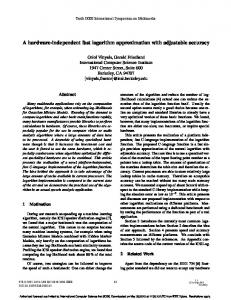
Proposition 2 (Average Running Time for α = 0.5) The average running time of Algorithm 2 on a binary n × n matrix A with P r(aij = 1) = 0.5 is 2n. Doing similar considerations (and some simplifying assumptions), the following estimate of the running time can be established for the general case α ∈ (0, 1): Proposition 3 (Average Running Time for α ∈ (0, 1)) Let A = (aij ) ∈ {0, 1}n×n be a random matrix with P r(aij = 1) = α ∈ (0, 1). Then the average running time T (n) of Algorithm 2 on input A can be estimated by
When the algorithm terminates, the coefficient matrix has been transformed into the unit matrix I and is found to be shifted one column to the right relative to its starting position. The passive column is the leftmost column and contains the solution
T (n) ≈
3 2 where P1 = α and Pk = −2Pk−1 + Pk−1 + Pk−1 , k > 1.
x = (1, 0, 1)T .
It is easy to see that the sequence P (k) converges to 0.5 for all α ∈ (0, 1). Since this sequence converges quite fast for α belonging to a large interval around 0.5, the running time is very close to 2n for almost all matrices except for very sparse (α < 0.05) or very dense (α > 0.95) matrices. The accuracy of our estimations has been approved by a real-life benchmark of an emulation of the proposed hardware architecture, where the number of required clock cycles to solve matrices of different dimensions and densities has been counted. The results of this benchmark are depicted in Figure 3 and Figure 2.
5.2. Performance In the following we analyze the running time of Algorithm 2 on input A ∈ {0, 1}n×n. Since we assume that an application of shif tup and eliminate can be computed in a single clock cycle, we simply have to count the required total number of these primitive operations. As we can easily see from Algorithm 2, always exactly n applications of eliminate are performed and only the number of shif tup applications varies, depending on the concrete matrix. Best and Worst Case Running Time. It is quite obvious, that in the best case we have no application of shif tup at all and in the worst we have exactly n − k applications of shif tup during the k-th iteration (assuming A is uniquely solvable). Hence, we obtain the following bounds on the running time:
5.3. Solving overdetermined LSEs In practice, solutions to overdetermined LSEs must be computed quite often. An LSE A · x = b, where A ∈ {0, 1}m×n and b ∈ {0, 1}m, is called overdetermined if m > n (i.e., more equations than unknowns). To compute a solution to an uniquely solvable7 overdetermined LSE using Algorithm 2, simply the additional rows must be taken into account in the definition (and actual implementation) of shif tup and
Proposition 1 (Bounds on Running Time) The time complexity T (n) of Algorithm 2 is bounded by n ≤ T (n) ≤
n X 1 , P k k=1
n2 + n = O(n2 ). 2
6 This is due to the fact that the XOR sum of two uniformly distributed bits is uniformly distributed. 7 A · x = b is uniquely solvable iff rank(A) = rank(A|b) = n, where A|b denotes the matrix A extended by the column vector b.
5 However, such a pointer to the passive column is not needed in the actual implementation of the algorithm.
4
puted in parallel by simply maintaining k passive columns (see Section 4) instead of 1. Clearly, the running time of the algorithm remains the same as in the case of a single passive column. In other words, a solution to A · X = B is computed where X = (x1 , . . . , xk ) is an n × k and B = (b1 , . . . , bk ) is an m×k matrix. Hence, as a special case we can compute the inverse of a regular n × n matrix A by simply setting B = I where I is the n × n identity matrix.
Figure 2. Size-dependency of running time. 4500 4000
Number of clock cycles
3500 3000 2500 2000
6. Further Applications
1500
Besides solving possibly overdefined medium-sized binary LSEs and computing matrix inverses, the presented architecture can be used for a whole suite of other useful applications. Moreover, the idea behind the architecture can lead to other very efficient matrix algorithms. In Subsection 6.1, we show how to use the approach to derive a very efficient matrix-bymatrix multiplication algorithm. Furthermore, we describe how to solve some other large matrix problems with our design and with the help of Strassen’s Algorithm. Finally, Subsection 6.3 shows how cryptanalysis of symmetric ciphers is affected by the design at hand.
1000 500 0 0
500
1000 Dimension
1500
2000
Figure 3. Density-dependency of running time. n=2048 n=1024
Average number of clock cycles
16000
6.1. Matrix Multiplication
14000 12000
Matrix multiplication is computationally equivalent to matrix inversion. To compute the product of two binary n × n matrices C = A · B using matrix inversion the following idea can be used. Let the 3n × 3n binary matrix D be defined as follows: „ «
10000 8000 6000
D=
4000
Then it is easy to that the inverse matrix of D has the following form: « „
2000 0 0
20
40 60 Density in percent
80
100
D−1 =
„
0 I
«
,b→
„
0 x
«
In A A·B 0 In B 0 0 In
Thus, by applying Algorithm 2 as outlined in Subsection 5.4 for the inversion of D one obtains a working and quite efficient algorithm for matrix multiplication. However, further improvements are possible by observing that one actually does not need to run the whole inversion algorithm: To get the result it suffices to perform elimination for the submatrix A only using the elements of the In in the middle of D for pivoting. Then the result of multiplication could be directly read out of the upper right n × n submatrix of D. Exploiting this observation leads to the following optimized algorithm for matrix multiplication which can be implemented in hardware in a similar way as Algorithm 2 (see Section 7). The running time of Algorithm 3 is n which includes
eliminate by replacing n with m every time it refers to the row count. More precisely, this means that in the k-th iteration the m − k + 1 first rows must be shifted up and each application of the elimination operation must also involve the additional rows. Then, by applying Algorithm 2, the matrix A and the passive column b are transformed this way: A→
In A 0 0 In B 0 0 In
,
where I is the n × n identity matrix and the n-bit vector x is the solution to the LSE.
5.4. Multiple b-Vectors and Matrix Inversion
Algorithm 3 Parallelized Binary Matrix Multiplication
Sometimes, solutions to LSEs of the form A · xi = bi (1 ≤ i ≤ k) are required for multiple different right hand sides bi and the same m×n coefficient matrix A. Using Algorithm 2 (without modifications), all solutions8 xi can be com-
Require: A, B, C ∈ {0, 1}n×n 1: C := 0 2: for k = 1 : n � do �T 3: C := C ⊕ a1k ∧ ~bk , . . . , ank ∧ ~bk
8 The algorithm still works if A · x = b is not uniquely solvable for i i some bi .
5
loading the row vector ~bk and the column vector ak in each iteration. The space complexity of the algorithm is about n2 .
and matrix multiplication recursively. As the optimal minimum splitting size is achieved, the hardware algorithms for inversion (Algorithm 2 used as outlined in Subsection 5.4) and multiplication (Algorithm 3) are to be applied.
6.2. Solving large matrix problems
6.3. Large matrix problems in cryptanalysis
Due to constraints on the fabrication process of custom designed hardware, Algorithms 2 and 3 can only be implemented for some limited value of n. This circumstance motivates the study of (recursively) splitting large matrix problems into smaller tasks, which finally can be solved directly in hardware using the above described algorithms. Strassen [16] suggested a number of matrix algorithms, breaking down the complexity of the basic matrix operations. Strassen’s algorithms provide a way of splitting large matrix problems into smaller ones. Here, only Strassen’s multiplication and inversion algorithms are discussed. The idea behind Strassen’s algorithm for matrix multiplication is that of partitioning matrices and of exploiting specific block representations of matrices to reduce the overall number of required bit operations. For two binary n × n matrices A and B, n being even, the product ` C11
C12 C21 C22
´
=C =A·B =
` A11
A12 A21 A22
´ ` B11 · B21
B12 B22
Large matrix problems over GF (2) are in general strongly related with cryptanalysis and in particular with algebraic attacks on symmetric ciphers which are generically applicable to any block or stream cipher. This is due to the fact that any output of a deterministic binary finite state machine can be represented as a (sometimes rather complicated) boolean function of the initial internal state bits and input values (if any) giving raise to an LSE over GF (2). In [1], an efficient algebraic attack on the keystream generator underlying the encryption scheme E0 used in the Bluetooth specification is proposed. The key length of the E0 keystream generator is 128 bit. The equation generation and linearization methods succeed to output an LSE with at most 224.056 unknowns9. Using our algorithms for binary matrix inversion and multiplication, it seems possible to build a hardware system which could significantly reduce the actual running time of the attack and achieve a good time/money ratio value. Another example is A5/2. Here, we mention the attack from [4]. To get the 64-bit long key, we have to solve max. 216 systems of 656 linear equations over GF (2). Our algorithm for solving LSEs can be directly applied in this attack, breaking down the overall running time significantly. If no data transmission and LSE construction overhead is considered, then the attack can be completed in 216 · 2 · 656 ≈ 226.36 clock cycles on a single ASIC, using the proposed hardware architecture. If the hardware runs with 1 GHz, the key could be found within about 86 ms (as compared to 40 minutes on a Linux 800 MHz PIII PC [4]). The attack can be parallelized by using several parallel ASICs. Moreover, all stream ciphers (e.g. LILI-128, Toyocrypt, Phelix, Snow, Turing, etc.) based on simple combiners and on combiners with memory10 are potentially vulnerable to algebraic attacks [8, 7, 9, 6]. In this context, the hardware approach to solve large LSEs may lead to a revaluation of the security of numerous well-known symmetric ciphers.
´
can be computed in the following way, as expressed using n n 2 × 2 matrix subblocks Aij and Bij : P1 P2 P3 P4 P5 P6 P7 C11 C12 C21 C22
= = = = = = = = = = =
(A11 + A22 ) · (B11 + B22 ) (A21 + A22 ) · B11 A11 · (B12 + B22 ) A22 · (B21 + B11 ) (A11 + A12 ) · B22 (A21 + A11 ) · (B11 + B22 ) (A12 + A22 ) · (B21 + B22 ) P1 + P4 + P5 + P7 P3 + P5 P2 + P4 P1 + P3 + P2 + P6 .
(1)
This matrix multiplication algorithm requires asymptotically O(nlog2 7 ) bit operations with a small constant compared to about O(n3 ) for the classical multiplication. Strassen’s algorithm for matrix inversion is related to the algorithm for multiplication. Let the n × n matrix C represent the result of inversion of A: ` A11
A12 A21 A22
´−1
=
` C11
C12 C21 C22
´
.
In terms of half-sized matrix blocks, the inverse matrix C can be calculated as follows: P1 P2 P3 P4 P5 C22 C12 C21 C11
= = = = = = = = =
A−1 11 A21 · P1 P1 · A12 A21 · P3 P4 + A22 P5−1 P3 · C22 C22 · P2 P1 + P3 · C21 .
7. Proposed Hardware Architecture We will now describe the basic functionality and the operating modes of the hardware architecture of Algorithm 2. First, we discuss the improvement in area-time (AT) complexity resulting from the new design.
(2)
7.1. Improvement of AT Complexity
Applying Strassen’s matrix multiplication algorithm for halfsized multiplications and Strassen’s inversion algorithm for half-sized inversions recursively, we obtain a complexity of O(nlog2 7 ) operations. Large LSEs, large matrix inversion problems, and large matrix multiplication problems can be split into smaller subproblems using Strassen’s algorithms for matrix inversion
The dramatic improvement in complexity of the average running time from a software implementation of binary 9 Since then some improvements of this attack have been proposed [2], [3]. 10 These are several parallel linear feedback registers filtered by a specially selected output boolean function with or without memory.
6
Gauß (Algorithm 1) of O( 14 n3 ) to the architecture at hand of O(2n) is achieved. We simply compute on all elements in parallel, yielding an improvement of O(n2 ) in the running time. However, we do not simply trade this improvement of O(n2 ) in running time with an equivalent increase in area. In fact, the design scales with the same asymptotic complexity as the standard Gauß in software. In both algorithms, the memory requirement scales with O(n2 ), i.e., with the number of elements of the matrix. The only difference is that the type of memory cells in our design is a bit more complex (smart memory). Thus, the algorithmic improvements do not only yield a much better running time, but also lower the overall AT product compared to the standard algorithm.
out2
out1
Figure 4. Signals from and to a basic matrix element.
clk rst
global signals
row_add
element
col_add
local signals
add
7.2. Functional Description In order to implement Algorithm 2 in hardware, we use a mesh structure of “smart memory” cells: The whole device consists of memory cells, which are able to execute the two basic operations defined in Subsection 5.1 in a single clock cycle. The design at hand comprises a parallel implementation of both operations where the pivot element is used as multiplexing signal for the appropriate result. This way, we save a clock cycle for deciding between the two operations. Besides performing the actual computation, both operations can also be used for initially loading the values into the design. Below, we will describe the basic constituents of the design and its interrelation. The terms in typewriter describe the name of the signals used in the figures. If appropriate, the corresponding variable of Algorithm 2 is provided additionally.
in2
lock_lower_row
in1
lock_row
add
element
add
element
col_add
element
col_add
add
element
add
col_add
Figure 5. Interconnection of elements in the architecture.
row_add add
add
element
add
element
add
element
element
row_add add
add
element
7.2.1 The Basic Cell and its Interconnection
element
row_add add
Each cell stores a single bit of the matrix (aij ) and has local connections to 4 direct neighbors: above (out1,lock row), below (in1,lock lower row), left above (out2), and right below (in2). Furthermore, it is connected to a global network: The global network comprises the signals from the pivot element (add=a11 ), the first element in the actual row (row add=ai1 ), and the first element in the actual column (col add=a1j ). Remark, that the used-flags for the actual row and the row below are provided by the signals lock row and lock lower row, respectively. Additionally, every element is connected to the global clock (clk) and reset (rst) network. Figure 4 depicts a single matrix element with all required local and global connections. All cells are aligned in a rectangular array as shown in Figure 5. The upmost left element is the pivot element of the matrix (a11 ). Its out1-signal is used as add-signal for the whole design. The out1-signals of all other elements in the first column are used as row add-signals for the actual row (ai1 ). Similarly, the out1-signals of all other elements in the first row are used as col add-signals for the actual column (a1j ).
add
element
add
element
element
7.2.2 Operation 1: Shift-Up In case of the actual pivot element being ’0’, the architecture performs a simple shift-up operation. All elements in the matrix with the used-flag set to ’0’ (lock row=0) simply shift their value one row up. Values in the upmost row will get shifted to the lowest unused row, resulting in a cyclic shift of all unused rows. All rows with the used-flag set to ’1’ (lock row=1) are not affected by the shift and stay constant. For the implementation, we will use the col addsignals to realize the cyclic shift from the first row to the last unused row. In the very beginning, values have to be loaded into the design. Since a reset of the design sets all elements to ’0’, a shift-up is applied n times until the matrix is completely loaded. In order not to load more than n values into the de7
sign, the loading phase is coordinated by an input multiplexer, switching off the input after n steps.
• A uniquely solvable LSE of rank n is always solved after exactly n-times Operation 2. Hence, the used-flag is the stop criterion.
7.2.3 Operation 2: Elimination
• An LSE with infinitely many solutions will never reach the stop criterion since infinitely many ’shift-up’ operations will occur at a certain point in time. To avoid such a dead-lock, we have to initialize a counter after every elimination step to limit the number of the subsequent ’shift up’-steps. In fact, this number must be less than the number of rows minus the number of locked rows. If not, we know that the LSE has no unique solution.
Operation 2 is invoked when the pivot element is ’1’ (add=1=a11). Every element except for those in the first row will compute an XOR with the upmost column entry (col add=1=a1j ) if the first entry in the row is ’1’ (row add=1=ai1 ). In the same step, the result is shifted to the element on the left in the upper row. The leftmost elements need no computation, since this step always yields a column consisting of zeroes and a single ’1’. The first row (with the pivot element) is unaffected and will be shifted to the last row and its used-flag (lock row) will be set to ’1’. The latter procedure prevents this row from being used again for pivoting.
• Invalid solution might appear in overdetermined LSEs when the b-vector has a ’1’ at a position corresponding to a zero row in the matrix. Thus, all such positions and have to be checked for ’0’.
7.4. Pipelining 7.2.4 End of Computation In order to achieve improved performance when solving many LSEs on a single “smart memory” chip, one can exploit the fact, that once a column has undergone column elimination, it does not have to be kept in memory anymore. Instead of keeping these columns, it is possible to preload a new column of the matrix which will be processed next, each time a column elimination is executed on the current matrix. With this approach, solving the current matrix and loading the next matrix could be done simultaneously. However, there are some potential caveats to take care of. It has to be ensured, that neither row permutations (caused by “pivoting” step) nor XOR operations (caused by “eliminate step”) can corrupt the columns of the partially loaded new matrix. This can for example be achieved with a flag similar to the already implemented used-flag, protecting the rightmost columns. In fact, the already implemented used-flag can easily be reused for this purpose.
When all rows have actively been used for pivoting, the usedflag reaches the topmost row and the architecture stops. In our design, this signal is used for indicating the end of computation. E.g., in the case of a single solution vector b, the result can simply be read from the first column by reading the column add-signals, which are wired out explicitly. Depending on the outer control logic, the topmost used-flag can be used to indicate the finished state and eventually stop the computation until the result has been read.
7.3. Solving Regular and Overdetermined LSEs For solving a regular LSE of rank n, we need n linearly independent equations. Hence, the design has to implement n rows of elements. After executing Operation 2 (see 7.2.3) n times, the solution is available. For the sake of simplicity, we have always assumed uniquely solvable LSEs in this paper. However, the design can easily be extended to handle overdefined LSEs and detect unsolvable LSEs, which we discuss now.
8. Implementation This section explains the methodology used to implement the previously presented architecture on FPGAs. Along with implementational results such as running time and area consumption, we provide estimates about a possible ASIC implementation.
7.3.1 Handling Overdefined LSEs In the same number of elementary operations, we can solve overdetermined LSEs, i.e., LSEs with rank n and m > n equations. In this case we only need to implement more rows of elements. The solution is obtained after n-times execution of Operation 2.
8.1. Methodology The architecture has been programmed in VHDL and is kept generic to allow for easily changing to arbitrary matrix sizes and different dimensions of the b-vector. The presented results originate from the running implementation. For synthesis, map, and place and route, Xilinx ISE 7.1 was used. Both behavioral and post-place-and-route simulation were done using Mentor Graphics ModelSimXE 6.0a. As device, we picked a contemporary low-cost FPGA, namely the Xilinx Spartan-3 XC3S1000 device.
7.3.2 Solvability of LSEs In some applications, the solvability of an LSE might not be known prior computation and we have to introduce additional logic for the detection of a valid solution. The architecture presented can be extended in order to distinguish between uniquely solvable and unsolvable LSEs. In such a case, we have to observe following facts: 8
For loading data from and storing data into the FPGA, we additionally implemented a simple interface to a host PC. It facilitates automated tests with several test values for architectures of different size. Remark, that the speed of the data in- and output is critical in case of an ultimate implementation. Hence, interfaces should be capable of running at highspeed (e.g., by using PCI-express or proprietary systems such as those on a Cray-XD1).
trix cell can be implemented with a few basic gates, as shown in Figure 6.
rst
clk
add in2
loc k_ row
loc k_ low er_ row
Figure 6. Schematic of the basic matrix cell.
8.2. Results in1
Table 1 presents the results of the implementation in terms of occupied FPGA resources depending on the size of the matrix. For the implementation, we have chosen a system of linearly independent equations of dimension n for n = {5, 10, 20, 50}. All values represent the results for the running and verified design on the actual FPGA. A basic element can be implemented in only ≈ 1.5 slices on average, which limits implementations on FPGAs to a maximum possible matrix size (see Table 1). With the current low-cost FPGA (Xilinx XC3S1000), matrix sizes of up to 70x70 are feasible. Note that we did not optimize the code for a certain FPGA. I.e., FPGA-specific optimizations might yield better area usage. The implementation at hand should be seen as proof-of-concept and not as ultimate design. However, the frequency of the matrix elements can be as high as 300 MHz which is close to the maximum possible frequency of the FPGA at hand. All designs have been tested at that frequency and displayed the correct results. Due to the restrictive nature of conventional FPGAs concerning the matrix size, an ASIC implementation should be considered for larger matrices and is discussed in the following section.
D Q
out2 row_add
Thus, the area consumption in terms of transistors or equivalent gates (standard CMOS logic) can be evaluated pretty accurate. As essential building blocks, we need XORs, ORs, ANDs, NOTs, and memory cells. The essential building blocks of the design are listed in Table 2, accompanied by the required number of gates for the implementation in standard CMOS logic. For a single element of the matrix, we estimate an equivalent of 54 gates.
Table 2. Equivalent gate-count for different CMOS logic cells (all quantities per bit). Logic type Equivalent Gates
Table 1. Area in slices for different matrix sizes on a Spartan-3 device (XC3S1000, 300 MHz). Matrix dimension Area / slices
5 54
10 187
20 656
out1
col_add
50 4004
XOR 3
OR 3
AND 4
NAND 1
SRAM 3
Obviously, the number of gates scales For comparison, a conventional Pentium 4 ”Prescott” processor accumulates approximately 125,000,000 transistors (0.09 microns). Hence, with current technology such an architecture for matrices up to a dimension of 1000 could be implemented on a die size of less than that for a conventional desktop CPU. Figure 7 shows the number of equivalent gates depending on the matrix size. Remark: The number of estimated gates is based upon simple 2-input logic gates. Hence, further optimization is possible and will result in a lower transistor count. Due to the regularity and relatively low latency of the design, clock frequencies in the range of 500 MHz up to a few GHz should be feasible.
8.3. Estimates for an ASIC Design Conventional FPGAs dispose of several features which can not be used for our design and, hence, the FPGA can not be utilized completely for the algorithm presented. When targeting a high-performant matrix solver for medium-sized matrices, a realization as Application Specific Integrated Circuit (ASIC) which can be tweaked completely to fit the requirements should be considered. Since the architecture itself has been successfully implemented on an FPGA, we now analyze its area consumption as ASIC for different matrix sizes and conclude with an estimate of the expected performance.
8.3.2 Expected Performance Depending on the matrix-size, the number of required building blocks together with Table 2 yield an approximation of the necessary number of equivalent gates, which are displayed in Figure 7. The figure includes an estimated overhead for the control logic. Loading an LSE of dimension 1000 into such a design, solving it, and reading out the solution could be done in 4 µs
8.3.1 Equivalent Gate Count of Basic Building Blocks As previously shown, the presented design is extremely simple and does not require complicated control logic. The ma9
Due to technological constraints, we always face a maximum possible matrix size which can be realized in practice. Consequently, we describe how to solve larger LSEs by breaking down the initial matrix size with Strassen’s Algorithm. As showed within the paper, further applications include fast matrix-by-matrix multiplication and utilization in cryptanalysis. In the latter case, time consuming parts of actual cryptanalytical algorithms can be accelerated by order of several magnitudes with the architecture presented.
Figure 7. Estimated number of equivalent gates depending on the dimension of the LSE
Number of equivalent gates (NAND)
1e+08
1e+07
1e+06
References 100000
[1] F. Armknecht. A Linearization Attack on the Bluetooth Key Stream Generator. Cryptology ePrint Archive: Report 2002/191 Available from http://eprint.iacr.org/ 2002/191, December 2002. [2] F. Armknecht. Improving Fast Algebraic Attacks. In FSE 2004, volume 3017 of LNCS. Springer Verlag, 2004. [3] F. Armknecht and G. Ars. Introducing a New Variant of Fast Algebraic Attacks and Minimizing Their Successive Data Complexity. In Mycrypt 2005, volume 3715 of LNCS, 2005. [4] E. Barkan, E. Biham, and N. Keller. Instant CiphertextOnly Cryptanalysis of GSM Encrypted Communication. In CRYPTO 2003, volume 2729 of LNCS, pages 600–616. Springer Verlag, 2003. [5] D. A. Buell, S. Akella, J. P. Davis, G. Quan, and D. Caliga. The DARPA boolean equation benchmark on a reconfigurable computer. Technical report, Department of Computer Science and Engineering, University of South Carolina, 2004. [6] N. Courtois. Cryptanalysis of Sfinks. Cryptology ePrint Archive: Report 2005/243. Available from http: //eprint.iacr.org/2005/243. [7] N. Courtois. Fast Algebraic Attacks on Stream Ciphers with Linear Feedback. In Crypto 2003, volume 2729 of LNCS, pages 177–194. Springer Verlag, 2003. [8] N. Courtois. Algebraic Attacks on Combiners with Memory and Several Outputs. In ICISC 2004, LNCS, 2004. [9] N. Courtois and W. Meier. Algebraic Attacks on Stream Ciphers with Linear Feedback. In Eurocrypt 2003, volume 2656 of LNCS, pages 345–359, 2003. [10] N. Galoppo, N. Govindaraju, M. Henson, and D. Manocha. LU-GPU: Efficient Algorithms for Solving Dense Linear Systems on Graphics Hardware. In ACM/IEEE SC—05 Conference, November 12-18, 2005. [11] W. Geiselmann, A. Shamir, R. Steinwandt, and E. Tromer. Scalable Hardware for Sparse Systems of Linear Equations, with Applications to Integer Factorization. In Workshop on Cryptographic Hardware and Embedded Systems — CHES 2005, pages 131–146. Springer. [12] M. Hestenes and E. Stiefel. Methods of conjugate gradients for solving linear systems. Journal Res. Nat. Bur. Standards, 49:409–436, 1952. [13] C. Kanzow. Numerik linearer Gleichungssysteme. Springer Verlag, 2005. ISBN 3-540-20654-X. [14] M. LaMacchia and A. Odlyzko. Solving large sparse linear systems over finite fields. In A. Menezes and S. Vanstone, editors, Advances in Cryptology - Crypto ’90, volume 537 of LNCS, pages 109–133, 1991. [15] D. Parkinson. A compact algorithm for Gaussian elimination over GF(2) implemented on highly parallel computers. Parallel Computing, 1:65–73, 1984. [16] V. Strassen. Gaussian Elimination Is Not Optimal. Numerical Mathematics, 13:354–356, 1969.
10000
1000 10
100 Dimension
1000
on average, assuming a clock rate of 1 GHz. Hence, up to 250 000 LSEs could be solved per second, assuming an adequate data input and output rate. For applications, an integrated pre- and post processing might be of interest in order to avoid the architecture from running idle. Only a high-speed stream of in- and outputs can bring out the best performance.
9. Conclusion The paper at hand seems to be the first contribution towards a highly efficient architecture for solving linear systems of binary equations. We formulate an algorithmic improvement for the well-known Gaussian elimination for the binary case, focussing hardware implementations. The new algorithm has been thoroughly analyzed and we provide lower and upper bounds on the running time as well as the average running time. Results from software experiments confirmed the correctness of our theoretical findings. As a result, an architecture implementing the proposed algorithm can solve an LSE over GF(2) of rank n in 2n steps on average, compared to 1 3 4 n steps for the standard Gaussian algorithm implemented in software. Besides the derivation and analysis of the new algorithm, a hardware implementation for LSEs up to a rank of 50 has been realized using VHDL. The resulting implementation can be operated at high speed (up to 300MHz) and was verified on a contemporary low-cost FPGA (Xilinx Spartan3-1000). In addition, we provide a first estimate of the area complexity of an ASIC design: With current technology, the design can be implemented for LSEs up to a rank of 1000 yielding conventional chip sizes. As a remarkable feature, the area complexity of the architecture scales with O(n2 ), which is similar to the standard Gaussian approach, though the complexity of the running time is O(n2 ) lower. Thus, the overall improvement regarding the AT -product is of order O(n2 ) compared to the standard algorithm in software. 10