INTERNATIONAL CONFERENCE ON ENGINEERING DESIGN, ICED'09 24 - 27 AUGUST 2009, STANFORD UNIVERSITY, STANFORD, CA, USA
A QUALITY FUNCTION DEPLOYMENT METHOD PATTERN LANGUAGE FOR EFFICIENT DESIGN D. Rogers and F.A. Salustri Ryerson University, Canada ABSTRACT Quality Function Deployment (QFD) is widely used throughout design processes to increase customer satisfaction. However, the method is sometimes not clearly understood and is at times confusing in its approach. Pattern languages, on the other hand, are used for ease of understanding and to convey information to those with little background on some topic. One might then consider the merits of creating a pattern language for QFD, to increase both understanding of the method and its usage in everyday design processes. In order to carry out this endeavor, the authors explore current quality function deployment methods and offer their own form of the process to solve some of the inconsistencies between current methods and to better suit the creation of the pattern language. A pattern language for quality function deployment method was then created and described in the paper, as well as examples of two specific patterns. This shows that the creation of a pattern language is possible, even for a difficult topic like quality function deployment and that it is useful to designers with little or no background in the quality function deployment method. Keywords: Quality Function Deployment, QFD, Product Design, Design Engineering, Patterns, Pattern Language 1 INTRODUCTION The purpose of this paper is to demonstrate that the idea of patterns and pattern languages can be applicable to a wide variety of topics, including complicated and hard to understand concepts like that of quality function deployment method; more frequently referred to as QFD. It is the hope of the authors that this demonstration will lead to more designers using the QFD method as a mainstream design process and as a result, better products will be designed. In this paper, the authors will first introduce QFD, and then describe pattern languages. We will then describe the construction of a pattern language for QFD in some detail. We cannot include the entire pattern language here, but two examples are provided. 2 QUALITY FUNCTION DEPLOYMENT Quality Function Deployment (QFD) method is a process of customer-based product design aimed at customer satisfaction, product quality, and product design timeliness and efficiency. Terninko [1] defines QFD as "...a detailed system for translating the needs and wishes of the consumer into design requirements for products or services" and can be extended to include "the design of systems, parts, processes, and control mechanisms”. QFD seeks to create a multidisciplinary team involved with the product from the very onset of the project until production. This allows the customer, designer, engineers, manufacturers, etc. to all be part of the design process, ensuring that the product will be as the customer expected at the end of the day. Doing so leads to a superior end-product over other, single disciplined, design processes. Terninko [1] shows that the QFD process leads to: • Shorter development time • Fewer engineering changes • Reduced introduction costs • Satisfaction of consumer needs and desires • Improved product manufacturability
ICED’09/200
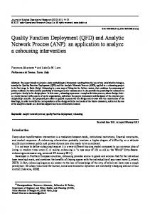
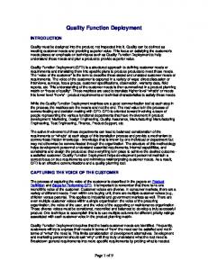
• Commonality of language • Development of a ready reference for the future One way to show the differences between traditional design and QFD-based design is illustrated in Figure 1 below:
Figure 1, Traditional vs. QFD Design Processes [1]
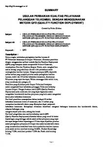
The above graphic identifies the problems in communication and visions as seen through the eyes of different stakeholders, during the design process. What QFD seeks to do is unite these visions such that all stakeholders are on the same page when it comes to designing and manufacturing the final product. The right half of the above graphic shows how all concerned parties are working with the same designed product, which leads to a better product at the end of the day. Since using the QFD process ensures that the needs of the customer are being fulfilled, the Kano model [2] predicts an increased customer satisfaction with the end requirement as can be seen by Figure 2 below.
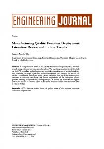
Figure 2, The Kano Model [2]
Kano’s model, as illustrated by the above graphic, shows that there is a correlation between fulfilling the customer’s needs and their satisfaction with the product. So, a product which fulfills all of the customer’s needs would then lead to fully satisfied customers, as opposed to a product which doesn’t meet all needs. Also, on the level of looking at only a single customer need, a product which fulfills the need completely will result in greater satisfaction than a need which is only partially fulfilled. Thus, the Kano model predicts that the QFD process will lead to greater customer satisfaction since it seeks to correctly fulfill all of the customer’s needs. Several QFD processes were studied and analyzed in creating the authors’ described process. These include, in alphabetical order: Crow [3], Hauser & Clausing [4], Munoz [5], Terninko [1], and Venien
ICED’09/200
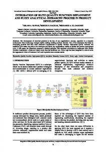
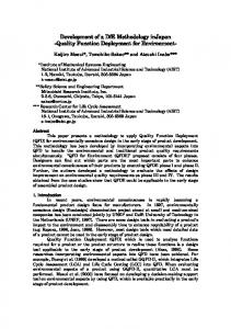
[6]. A graphic showing the differences between the above-mentioned QFD methods is given in Figure 3 below.
Figure 3, Comparison of Current QFD Methods
As can be seen by Figure 3 above, the four studied QFD methods differ in many ways, though they essentially describe the same process. Also, some of the above methods seemingly left out important phases of the design process or steps were repetitive. It is for this reason that the authors decided to create their own QFD process for use in making their QFD pattern language. First, Hauser & Clausing’s [4] method seems to miss some important steps, namely the: concept generation, winning concept selection, and competition benchmarking. Also, steps 3 and 4 in their method (also seen in Venien [6]) are similar enough to be combined into a single step, as Terninko [1] has done in step 5 of his method. Next, step 3 of Munoz’s [5] method, seemingly wastes an extra step, when the other methods combine this into the previous step. Finally, Venien [6] describes a step 2, which in the authors’ views should be a part of the concept generation. Also, the authors wished the process to more closely reflect other design processes for ease of implementation and use. Therefore, the authors’ QFD method combines the above mentioned methods, while revising the steps which were thought to be unnecessary or inclusive in another step. The result of this is described in the section below. 2.1 A Revised QFD Method Since there existed a problem with a non-unified QFD process, as described above, the authors decided that a new QFD process should be created, which combines and captures the ideas of all the studied QFD methods. While creating yet another method of QFD to the already substantive list of methods seems counter productive to the efficiency of the design process, it is arguably better to do this for the purpose of creating the pattern language for QFD. Reasons for this include: combining the advantages of all methods into the new method; allowing the new method to omit or rework confusing or ambiguous steps in other methods; tailoring the QFD process to better suit a pattern language form; and addressing known issues in current methods. A more detailed graphic showing the authors’ QFD process, including extended information on individual steps within the 6 major steps, is seen in Figure 4 below.
ICED’09/200
Figure 4, The Integrated QFD Method
As can be seen, the modified “integrated” QFD process includes the major steps from all previous methods, while at the same time presenting them in a more understandable and logical flow. This adds greatly to the ability to use a pattern language to describe the QFD process. Also, the form of the authors’ QFD process is similar to that seen in systems engineering, but is also widely accepted in engineering design [7]. One aspect of the QFD process which is not identified in the graphics of all the above mentioned QFD processes is the creation of the House of Quality (HOQ). The HOQ is used to check the final design against the user requirements to see if the product satisfies or will satisfy the user’s needs and is created through information gathered during the steps of the QFD process. It is perhaps the best known artifact of the QFD method. A step-by-step description of creating the HOQ is as follows: 1. Functional requirements (FRs), or “customer requirements” as labeled in the graphic, on the leftmost portion, as obtained from Steps 2 & 3. a. with their associated weightings, as decided by a pairwise comparison, directly to the right of each corresponding requirement. 2. On the right side of the house, directly opposite the FRs, are listed the customer evaluations of the competition, or “customer perceptions” as labeled in the graphic. 3. Across the top of the house are placed the performance metrics (PMs), or “technical/design requirements” as labeled in the graphic, that are likely to affect one or more of the FRs. A + or sign in front of each PM indicates whether the design wishes to increase or decrease the value to increase customer satisfaction. 4. The body of the house is termed the “interrelationship matrix” and is filled out by the team (where they “seek consensus on these evaluations, basing them on expert engineering experience, customer responses, and tabulated data from statistical studies or controlled experiments” [4]). This is done using symbols or numbers as a scale (as determined by the team) to indicate how much each PM affects each FR. 5. Once the body is completed, technical evaluations, or “targets” as labeled in the graphic, are placed below the FRs. Technical evaluations are the values obtained from measuring each PM for the team's design as well as for the competition. As an example, if a PM is ‘nominal tire pressure', then the technical evaluation would be a physical sample taken from the design and may be '220 kPa'.
ICED’09/200
6.
The last portion is a triangular roof matrix, or “technical correlation matrix” as labeled in the graphic, placed above the PMs. This matrix helps show which engineering features must be improved/changed in parallel in order to have a net positive effect on the overall design. Figure 5 below depicts a typical form for the HOQ.
Figure 5, A Traditional HOQ Setup [5]
3 PATTERNS AND PATTERN LANGUAGES The idea of patterns and pattern languages have been around for a long time, though their everyday use is currently somewhat limited. While being used quite extensively in the computer programming field and somewhat in the architecture field, their use in engineering and design is not abundant. This section will show how the use of patterns and pattern languages is convenient and useful as a tool to explain the QFD method and help make this method of design more popular with the community. 3.1 Patterns Patterns, as first described by Alexander [8], can be thought of as 'recipes' to create a specific artefact. Much like a cooking recipe might tell you how to cook a key lime pie, a pattern describes a process, method, or activities related to creating the artefact which they describe. Patterns are useful in that they seek to describe things in simplistic terms so as to appeal to a broader audience, even those with little to no background in the discipline of the artefact. In this way, patterns are seen as extremely useful ways to convey information to a larger proportion of people then would be possible with a focused textbook or refereed paper on the subject matter. It is usually the case that patterns pertain to a best practice of sorts. This is due to the fact that most industries tend to "throw away the book" as it were and use the knowledge and experience of those in positions of seniority when creating the artefacts. A best practice can be defined as; a widely accepted method to solving a particular problem or an accepted means to a particular end. Salustri & Adrees [9] suggest that best practices lend themselves particularly well to the creation of patterns. There are many different forms to a pattern, but the overall layout of such is generally similar. The process described herein will discuss the parts of the patterns as used by the author to build the QFD pattern language, though most pattern templates contain the same or similar areas. 3.1.1
The Pattern Template
Each pattern starts with a “Title” that describes the artefact that is created through the use of the pattern (as an example, the title might be "Key Lime Pie"). The first part to a pattern is the problem which the pattern addresses or solves (continuing the above example, the problem statement might be "There is an abundance of limes in the area and we want to
ICED’09/200
use them to create a tasty treat"). A problem statement should be kept to a short phrase or sentence describing what the pattern will do, or the artefact that the pattern creates and is written for laypersons. It is acceptable to place some key drivers for the pattern in this section as they indicate more precisely the what, why, where of the artefact and can help users to decide if this pattern is exactly what they are looking for or if they need to pick a different pattern for their problem (key drivers for the working example might be geographical location, reasons behind the lime abundance, what is meant by a "tasty treat", and could even include a list of ingredients used in the recipe). One could also include specifics as to when and where to use the pattern, or even when not to use it. This section will be indicated using the "Problem" heading. Next, all patterns contain a solution to the problem defined in the previous section. This is the "meat" of the pattern and should be a well worked process to create the artefact defined in the problem (this would be analogous to the directions to prepare the pie crust, filling, cooking directions, etc for the above example). As with the problem, this section should use 'common language' to describe the process so as to appeal to all users of the pattern. This section should be well laid out and describe in detail exactly how to go about creating the artefact described. This section will be indicated using the "Therefore" heading. Thirdly, a pattern should contain an area to describe the consequences or cautionary areas in the use of the pattern. This can describe common problem areas, consequences of the realization of the artefact, how to analyze results, or new problems that could arise (in the working example, this section might include "creating a really good key lime pie may cause neighbours to visit more often in hopes of eating the pie" or "caution should be exercised in the final minutes of baking as the pie crust could burn, ruining the pie", etc). This section will be indicated using the "But" heading. Lastly, all patterns have a section which indicates similar patterns to the one used, or areas to find more information on the specifics in the body of the pattern. This section is useful when there are many similar artefacts to choose between or in this case, in the creation of a full pattern language as it will provide the links to the relating patterns within the language. This section will be indicated using the "Related Info/Patterns" heading. The pattern template used by the authors in creating the QFD pattern language is shown in Figure 6 below, with the major sections shown in block lettering. TITLE Authorship Information PROBLEM Summary Drivers Exposition (optional) Counterindications (optional) THEREFORE Structure Realisation BUT (Consequences) RELATED INFO/PATTERNS (optional) Figure 6, A Pattern Template
For other templates for creating a pattern, the reader is encouraged to see the following references: • Alexander [8] • Erickson [10] • Jessop [11] • Salustri [12] • Salustri & Adrees [9] 3.2 Pattern Languages Pattern languages are then the culmination of patterns, linked in a way so as to provide greater meaning or to create a more complex artefact. Much like single words are linked through certain grammatical relations to make sentences and further a communicable language, patterns are linked through certain relations to create a pattern language (for the working example, the pattern for key
ICED’09/200
lime pie might be linked to many patterns to make other pies and therefore create a pattern language (or cookbook) for pies or desserts). Unlike the patterns themselves, there is no particular organizational structure or suggestive means for creating the connections and relationships between patterns when forming the pattern language. Therefore, it is an exercise for the pattern language designer to decide how they best want to create the language logistics. There are some basic guidelines that suggest that the pattern language be organized in such a way as to maximize informational output and ease of use. Since patterns are useful due to their ease of use, the pattern language resulting from many patterns should also retain this feature and be easy to use and user-friendly. 4 A QFD PATTERN LANGUAGE Since the QFD method is generally confusing for first time users, the use of an easy-to-understand pattern language helps to increase user friendliness and uptake of QFD method in the design process. This in turn should give way to better products being designed. As a first step to creating the full pattern language for the QFD method, a logical map of the QFD steps was created to aid in the pattern language design. The logical map was created in order to keep track of and to illustrate the process of working through the steps of the QFD pattern language, as well as to show the actual patterns contained in the language and their interconnections. This logical map was created, modified, and tweaked fully before even the first pattern of the language was created. As a result, the final QFD pattern language displays a smooth flow between steps and a more consistent ‘grammatical relation’ within the pattern language. A graphic of this logical map can be seen in Figure 7 below.
Figure 7, Logical Map of the QFD Pattern Language
Here, references to actual patterns in the pattern language are shown by encapsulating the pattern in [XX], where “XX” is replaced by the title of the specific pattern. The top-most pattern here is then “[QFD Pattern Language]” and is the root of the language for the authors’ QFD process, as described above. This top-most pattern can also be seen in Figure 8 in the Appendix of this paper, as an example. Though the focus of this paper is on the creation of the QFD pattern language, it would be impossible to go into detail for each of the individual patterns within the pattern language. Thus, the reader is encouraged to view the two examples of interlinking patterns from the QFD pattern language in the Appendix of this paper and also to visit the following website to view the QFD pattern language in its entirety in order to get a better feel for the results of this research: http://deseng.ryerson.ca/xiki/Patterns/QFD_Pattern_Language. The patterns in Figure 8 and Figure 9 of the Appendix of this paper, along with the map of the language in Figure 7, show how a pattern language is used effectively to make the interrelations between the individual patterns. As is shown by the examples, “Identify I/O, Subsystems, and Relations Leading to a PAS” is a pattern within “Concept Generation Step”, which is in turn a pattern
ICED’09/200
within the “QFD Pattern Language”. Thus, it is shown that this is a pattern within a pattern within a pattern and is the basis for the creation of the pattern language. Also, the astute reader will notice that not only is there a hierarchical relation within these patterns, but also a parallel relation linking patterns which talk about other patterns on the same level. Examining Figure 9 from the Appendix, one might notice that in the pattern itself it links back to the “customer needs” from Step 2. This shows the language emerging as not just a simple hierarchical organization of steps in the QFD process, but a more intertwined connection of knowledge. This phenomenon is also found in other places in the QFD pattern language and can be accessed via the web address above to further the example of interconnectivity of patterns. The following example will demonstrate a scenario where this QFD pattern language might be used: • A designer is approached by a firm who wishes to design a new product • The firm is conscientious about sustainability issues and does not want to waste time, money, and resources on poor designs or fixing problems along the way • Therefore, the firm states explicitly that they want the QFD method employed in the design process for their product • Having never heard of or used the QFD method before, the designer needs an easy-to-use ‘tutorial’ on how to use the QFD method successfully • The designer finds that overly large texts on QFD is too difficult to follow and to extract the exact steps needed and wants something more like a ‘recipe’ to follow • The designer then uses the proposed QFD pattern language outlined in this paper, since it is concise and to-the-point on going through the QFD process • Both the designer and the firm benefit from a well-designed product at the end of the day 5 CONCLUSIONS It is shown here that the creation of a QFD process through the use of a pattern language was a valuable effort and can be used in the design process. The pattern language was successfully created based on the authors’ own QFD process, which was created in part due to the drawbacks of using any one of the current methods, and also to better fit the application of the pattern language idea. Use of a pattern language to describe the QFD process was done in order to reduce the complexity of trying to learn the QFD method and also to increase uptake of QFD by designers; thereby increasing customer satisfaction, lowering project run times and costs, and increasing the effectiveness of the design process. In future work, the authors are seeking industry partners with whom to test the ideas and content explored in this paper. It is the intent that partners would help the authors with further research into the usage of pattern languages as tools of information conveyance and also research into the QFD method and its uses and results. Also, some future testing of this QFD pattern language would help to validate the arguments in favour of using a pattern language and also for using the QFD process.
ICED’09/200
6
APPENDIX
QFD PATTERN LANGUAGE 1. PROBLEM A design problem requires solving, but the design team wants to ensure that the customer will be satisfied at the end of the day.
2. THEREFORE The following QFD process pattern language can be followed in order to solve the design problem.
Step 1: Identify Customers Step 2: Determine Customer Needs/Requirements Step 3: Derive Product Requirements & Performance Measures Step 4: Concept Generation Step 5: Set Measurable Design Targets Step 6: Determine Manufacturing Process Steps & Deployment After the above 6 steps of QFD have been completed, creation of a house of quality (HOQ) for checking the results against the design problem should be carried out. The HOQ also measures customer satisfaction with the design concept and can show areas which need improvement before the manufacturing process. If the HOQ shows problematic areas or parts of the design which might be insufficient, the design team should revisit some or all of the steps in the QFD process. Upon successful completion of the 6+1 steps of the QFD method, the design team will have used the QFD design process to create a marketable and useful product, which satisfies the user's defined needs; thereby reducing total project cost and time to deployment.
3. BUT The design team must first decide whether to apply this QFD process to the system as a whole, to a single subsystem, or individually to each subsystem in the design BEFORE starting the process. This is essential since knowing the project boundaries has implications in even the first steps of the QFD design process.
4. RELATED INFO/PATTERNS References Figure 8, Top-most Pattern in the QFD Pattern Language
ICED’09/200
CONCEPT GENERATION STEP 1. PROBLEM In order to continue with the design problem, concepts must be created to satisfy the voice of the customer.
2. THEREFORE The design team must first go through a process of laying out the systems, subsystems, and inputs and outputs of the design, then move on to ideation and generation of concepts in order to evaluate their ability to satisfy the customer needs.
Step 4.1: Identify I/O, Subsystems, and Relations Leading to a PAS In this first step, the design team needs to identify specifics of the product to be designed, including: the inputs and outputs, subsystems and sub-subsystems, and transformational relations that will occur across the system boundaries.
Step 4.2: Generate Concepts and Choose a Winner Once the items in Step 4.1 have been identified/created, it is then the job of the design team to generate a multitude of concepts from which to choose a winner and proceed into the later stages of design.
Step 4.3: Evaluate the Winner Against any Competition A key to assuring success and customer satisfaction is to evaluate the concept winner against some or all of the relevent competition in the market. This will show whether the concept is indeed as good as the team thought, while showing any deficiencies in performance relative to the current competition.
3. BUT Being an important step in the QFD process, concept generation and evaluation can become one of the more time-consuming tasks in the process. Therefore, it is important that the design team set aside enough time for this step and possibly revisit it if things start to go a stray in further steps. Cutting team ideation sessions or group meetings short in this step in a no-no.
4. RELATED INFO/PATTERNS Previous Step Next Step Figure 9, 2nd Level Pattern in the QFD Pattern Language
ICED’09/200
REFERENCES [1] Terninko, J. Step-by-Step QFD: Customer-Driven Product Design, 1997 (St. Lucie Press, Boca Raton). [2] Kano, N. Attractive Quality and Must-be Quality. The Journal of the Japanese Society for Quality Control, April, 1984, pp.39-48. [3] Customer-Focused Development with QFD. Crow, K. 2002. DRM Associates. 6 Feb. 2008. . [4] Hauser, J.R. & Clausing, D. The House of Quality. Harvard Business Review, May-June, 1988, pp.63-73. [5] Munoz, D. Quality Function Deployment (QFD). Online lecture. 1999. 18 Jan. 2008. [6] Quality Function Deployment Method. Venien, A. 12 Jan. 2006. Ryerson University. 17 Oct. 2007. http://deseng.ryerson.ca/xiki/Patterns/Main:Quality_function_deployment_method [7] Hubka, V. & Eder, W.E. Engineering Design: General Procedural Model of Engineering Design, 1992. Edition Heurista, Zurich. [8] Alexander, C. A Pattern Language: Towns, Buildings, Construction, 1977 (Oxford University Press, New York). [9] Salustri, F. & Adrees, M. Using Design Pattern Languages to Structure Best Practices in Design Engineering, 2005. Unpublished manuscript. [10] Erickson, T. Supporting interdisciplinary design: Towards pattern languages for workplaces. Workplace Studies: Recovering work practice and information system design, 2000 (Cambridge University Press, ). [11] Jessop, A. Pattern Language: A Framework for Learning. European Journal of Operational Research, 2004, 153(2), pp.457-465. [12] Pattern Template. Salustri, F. 23 Nov. 2004. Research notes. 07 June 2007.
Contact: F.A. Salustri, PhD, PEng Ryerson University Department of Mechanical and Industrial Engineering 350 Victoria Street Toronto, Ontario M5B 2K3, Canada tel: +001-416-979-5000 x7749 fax: +001-416-979-5265 email:
[email protected] URL: http://deseng.ryerson.ca/~fil Damian Rogers is a PhD candidate in Mechanical Engineering at Ryerson University, studying Design for Sustainability. He holds an MASc degree in Space Sciences from the International Space University (France) and has worked at NASA JPL. He has an interest in flight and space, the European Space Agency (ESA) Student Parabolic Flight Campaign, where he logged zero-gravity flight time. Filippo A. Salustri, PhD, PEng has been teaching and researching design engineering since 1989. He has been involved with the design of cars, aircraft, spacecraft, robots, structures, toys, appliances, and medical equipment. He is a member of the Design Society, the Design Research Society ASME, CSME, IEEE, and INCOSE. He is currently an Associate Professor of Mechanical Engineering at Ryerson University.
ICED’09/200


![[PDF] QFD: Quality Function Deployment - Google Sites](https://m.moam.info/img/260x300/pdf-qfd-quality-function-deployment-google-sites_6477c7f9097c4744708c185c.jpg)