energy are used to solve for the liquid film thickness, pressure drop, and heat transfer coefficient. Closure .... rated, an energy balance dictates that the equilibrium vapor ... The relations above are not yet closed; they require that 7i, E,,. Ed, and ...
A separated flow model for predicting two-phase pressure drop and evaporative heat transfer for vertical annular flow Feng Fu and James University
of Florida,
F. Klausner
Department
of Mechanical
Engineering,
Gainesville,
Florida,
USA
A separated flow model has been developed that is applicable to vertical annular two-phase flow in the purely convective heat transfer regime. Conservation of mass, momentum, and energy are used to solve for the liquid film thickness, pressure drop, and heat transfer coefficient. Closure relationships are specified for the interfacial friction factor, liquid film eddy-viscosity, turbulent Prandtl number, and entrainment rate. Although separated flow models have been reported previously, their use has been limited, because they were tested over a limited range of flow and thermal conditions. The unique feature of this model is that it has been tested and calibrated against a vast array of two-phase pressure drop and heat transfer data, which include upflow, downflow, and microgravity flow conditions. The agreemsents between the measured and predicted pressure drops and heat transfer coefficients are, on average, better or comparable to the most reliable empirical correlations. This separated flow model _is demonstrated to be a reliable and practical predictive tool for computing two-phase pressure drop and heat transfer rates. All of the datasets have been obtained from the open literature. 0 1997 by Elsevier Science Inc. Keywords:
two-phase
annular
flow; convective
heat transfer;
Introduction Two-phase annular flow patterns with heat transfer are prevalent in many industrial processes. The reliable prediction of pressure drop and heat transfer rates associated with these processes are essential to developing more reliable, efficient and cost effective heat exchangers; reducing or eliminating costly shutdowns caused by equipment failure; and achieving energy savings through optimization of thermal processes. The annular flow pattern is one that frequently occurs in conjunction with evaporative heat transfer in tubes. Annular flow is characterized by an inherently unsteady liquid film flowing along the wall parallel to a flowing vapor core carrying entrained liquid droplets. The liquid film structure is influenced by many system variables, some of which are system geometry, flow orientation (up, down, microgravity, or horizontal flow), and liquid/vapor velocity difference. Kenning and Cooper (1989) identified two heat transfer regimes associated with evaporative two-phase flow heat transfer: the convective regime and the nucleate boiling regime. In the convective regime, nucleate boiling is completely suppressed, and the heat transfer is governed by bulk turbulent motion of the liquid film. Heat transfer in the nucleate boiling regime is governed by the incipience, growth, and departure of vapor bubbles along the heating surface. Klausner and Mei (1995) and Thomcroft et al. (1996) recently identi-
Address reprint requests to Dr. J. F. Klausner, University of Florida, Department of Mechanical Engineering, P.O. Box 11630, Gainesville, FL 3261 l-6300, USA. Received 26 August 1996; accepted 4 February 1997 Int. J. Heat and Fluid Flow 18: 541-549, 1997 0 1997 by Elsevier Science Inc. 655 Avenue of the Americas, New York, NY 10010
pressure
gradient
fied a dimensionless variable that can discriminate the convective and nucleate boiling heat transfer regimes. This work is specifically concerned with two-phase annular upflow, downflow, and microgravity flow pressure drop and evaporative heat transfer in the convective regime. Analytical two-phase flow models typically treat the flow as steady, simplify the geometry of the flow structure, and use conservation of mass, momentum, and energy to predict pressure drop and heat transfer rates. Such models are attractive, because they attempt to physically model the dominant heat and momentum transport mechanisms, and thus there exists potential for such models to have broad applicability. They also give detailed information on the flow and thermal fields. The drawback of these models is that they require empirical closure relations, and typically these are tested against only a limited range of data. Two-dimensional (2-D) finite-difference models have been proposed by Lai (1992) for flow boiling and Mandrusiak and Carey (1990) for annular flow with offset strip fins. Separated flow models are those in which one-dimensional (1-D) conservation equations are applied separately to the vapor core and liquid film, and are coupled through closure relations applied at the liquid/vapor interface. Separated flow models have been discussed in detail by Hewitt and Hall-Taylor (19701, Carey (19921, and some more recent models have been proposed by Stevanovic and Studovic (19951, Owen and Hewitt (19871, and Sun et al. (1994). These models have only been calibrated over a narrow range of parameters and, thus, do not have broad applicability. In this work a separated flow model, boundary conditions, and closure relations are presented as analytical tools to predict pressure drop and heat transfer rate for two-phase annular upflow, downflow, and microgravity flow in tubes. An extensive 0142-727)(/97/s PII so1 42-727x(97)00001
17.00 -5
A Separated
Flow Model:
Fu
experimental database has been compiled, and the empirical closure relations are calibrated against those data. It is demonstrated that separated flow modeling is a reliable alternative to empirical pressure drop and heat transfer correlations. This approach is a significant departure from the majority of two-phase heat transfer correlations, which attempt to cover both the convective and nucleate flow boiling regimes.
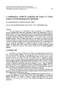
Separated
Vapor Core
nbmined Droplets
flow model formulation
Consideration is given to the flow configuration depicted in Figure 1, in which there exits cocurrent annular flow with entrainment through a round tube and heat input at the wall. The following assumptions are inherent in the model: (1) the flow is incompressible; (2) the flow is steady; (3) the liquid film thickness is uniform around the tube periphery; (4) the liquid/vapor interface is smooth; (5) the pressure is uniform in the radial direction; (6) evaporation occurs at the liquid/vapor interface; and (7) liquid droplets entrained in the vapor core are uniformly distributed. Conservation
I Figure
equations
Following Hewitt and Hall-Taylor (1970) a force balance on a cylidrical element of the liquid film in which acceleration is ignored leads to,
7
Idealized sketch of annular
Liquid
Film
flow with heat transfer
the radial coordinate, y is the distance from the wall, the subscripts i and I, respectively, denote the liquid/vapor interface and the liquid, and the + applies to upflow; whereas, - applies to downflow. Equations (1) and (2) may be combined, which results in
(1) and using the concept of eddy-viscosity,
T
du
dy=
(2) lJ,f+cmP/
where T is the shear stress, dp/dz is the axial pressure gradient, p is the density, g is the gravitational acceleration, u is the velocity, p is the dynamic viscosity, E, is the eddy-viscosity, r is
Notation B0 Co d, dp z
! hfg g G Pr, 4w r r0
Re, Re, T U
u* n Vui
542
boiling number ( = q,/G&J empirically determined distribution pipe diameter, m pressure
where r,, is the pipe radius, and 6 is the liquid film thickness. Following Hewitt and Hall-Taylor (19701, a momentum balance
Y Y+ z
radial coordinate, m wall units (=yu*p/p) axial coordinate, m
parameter Greek
gradient (Pa/m)
entrainment rate friction factor heat transfer coefficient (W/m’K) latent heat of vaporization (J/kg) gravitational acceleration (m/s2) total mass flux (kg/m* s) turbulent Prandtl number (= E,/E~) wall heat flux (W/m*) radial coordinate, m pipe radius, m liquid phase Reynolds number ( = G(1 -x)d,/pr) vapor-phase Reynolds number ( = Gxd,/p,,) temperature, “C velocity (m/s) friction velocity [ = Jml quality empirically determined drift velocity (m/s)
: El?l Ed
1 CL P (T 7
void fraction liquid film thickness, m eddy-viscosity (m’/s) eddy thermal diffusivity (m*/s) thermal diffusivity (m*/s) dynamic viscosity (kg/ms) density (kg/m3) interfacial tension (N/m) shear stress (N/m2>
Subscripts
; 0
sat V
24
interfacial liquid wall saturation vapor two-phase
lnt. J. Heat and Fluid Flow, Vol. 18, No. 6, December 1997
A Separated Flow Model: Fu on the vapor core, which includes momentum entrainment, results in
exchange
due to
dp _=dt
cakulatc
llmrmophysiulPmpwtiw1
i
PI Film Thickness
(1 -J!z)2(1 -x)*X +
p,(l -a)
- p,,uE(l
E(1 -x)x -XI
(4)
+ “PO
Cnkulatedpldzwio~ Eq. (4) Cakuhtcu(y)wingEq. (3)
11 where E is the liquid mass fraction entrained in the vapor core, G is the total mass flux, .r is the vapor quality, CKis the vapor volume fraction, and the subscript u denotes the vapor. A mass balance on the liquid film is expressed as
;G(l
-x)(1
check tke Mar: Bahnce Using IQ. (5)
-E)=p,
Consideration is now given to energy transport through the liquid film. Because turbulent diffusion across the thin film is typically much greater than convection downstream, a simplified energy equation is
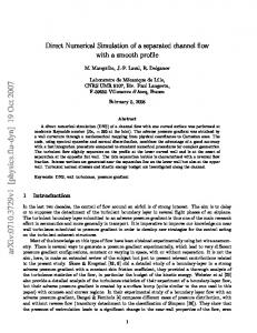
Figure 2
Flow chart of solution
procedure
(1) An initial guess is made for the film thickness
tion 4 is used to compute the pressure where thermal rated, quality u!x
n, is the liquid thermal diffusivity, and E” is the eddy diffusivity. Assuming that the two-phase mixture is satuan energy balance dictates that the equilibrium vapor varies as
_- 29,
z-
(7)
Grohfg
where q,,, is the wall heat flux, and hfg is the latent heat. The heat transfer coefficient is defined as (8)
where T, and T,., are the respective wall and saturation atures. The required bounldary conditions are
temper-
at the wall (y = 0):
8, and Equadp/dz.
(2) Equation 3 is used in conjunction with the velocity boundary conditions to compute the liquid film velocity profile u(y). (3) The velocity profile is used in Equation sides of the equation balance.
5 to check if both
(4) If both sides of Equation 5 balance, Equation 6 is used in conjunction with the temperature boundary conditions to compute the liquid film temperature profile T(y), and the heat transfer coefficient defined in Equation 8 is evaluated. If Equation 5 does not balance, steps l-3 are repeated. Empirical closure
9, h,, = ~ Tw- L
gradient
relations
One of the most important variables that influences the solution of the separated flow model is the interfacial shear stress. After examining many different empirical correlations for interfacial shear stress, it has been found that a modified form of the correlation proposed by Henstock and Hanratty (1976) gives the best results. The equations required to comuute the interfacial shear stress are as follows,
(9)
and at the liquid/vapor interface (y = 6): du dy=
Ti
kk + E,PI ’
(1 + 14OOFP
fi
T= T,,.
z=1+1400F
(101
13.2G,F
Solution procedure The relations above are not yet closed; they require that 7i, E,, Ed, and E be specified. The closure relations used for this model are discussed shortly. Given the appropriate closure relations, Figure 2 is a flowchart describing the solution procedure to the above equations, which is also summarized as,
Int. J. Heat and Fluid Flow, Vol. 18, No. 6, December
1997
F = [ (0.707Refi5)*”
+ (0.0379Re~)2’5]0’4 (;)“‘(a)” Rer* (11)
543
A Separated Flow Model: Fu where
u”=-,
Gx
Gx2r, Re, = , Wf=
P”
P”
f, = 0.046Re;0.2,
G(1 -x)(1
- E)2r,
PI
Go = 3. s “U”
In Equation 11 ml and m2 have been empirically determined based upon the available pressure drop data. For water ml = 1.0, and ml = 1.2 for all other fluids tested. It has also been found that m2 = 0.70 gives the best fit for the upflow data, while m2 = 0.80 gives the best fit for the downflow data. Detailed turbulence measurements for annular flow liquid films are not available. The usual practice in treating the liquid film eddy-viscosity is to assume the wall turbulence is similar to that of single-phase flow and use single-phase flow correlations for the liquid film eddy-viscosity. Although such an assumption has yet to be experimentally validated, modified single-phase flow eddy-viscosity and turbulent Prandtl number correlations will be used here. Following the discussion of Kays (1994), the liquid film eddy-viscosity and turbulent Prandtl number are respectively computed from
where the boiling number is defined as B, = q,/Ghfg. Evidence that the bulk turbulence is enhanced with evaporation is provided by Klausner et al. (19901, where it is shown that under otherwise identical flow conditions, the frictional pressure gradient increases with increasing heat flux. It is noted that in implementing the solution procedure, an initial guess must be made for the friction velocity u*. In subsequent iterations, u* is computed from its definition and using Equation 2 to evaluate the wall shear stress. Many correlations have been proposed for the liquid entrainment, but there tends to be a large scatter in the data, and most of these correlations have been based on air/water systems. Instead of using an entrainment correlation, it is noted that the mass fraction of liquid entrained in the vapor core is related to the liquid film thickness and vapor volume fraction through E=
1
--X
a
l_
[
(1 -6/ro)’
and a Zuber-Findlay success in predicting (Y=
,
PI
1 --X PO
(1965) type model that has demonstrated vapor volume fraction is instituted.
1 (16)
y+