A Study of Parallel Particle Tracing for Steady-State and Time-Varying Flow Fields Tom Peterka Robert Ross Argonne National Laboratory Argonne, IL, USA
[email protected] [email protected]
Boonthanome Nouanesengsy Teng-Yok Lee Han-Wei Shen The Ohio State University Columbus, OH, USA
[email protected] [email protected] [email protected]
Wesley Kendall Jian Huang University of Tennessee at Knoxville Knoxville, TN, USA
[email protected] [email protected]
Abstract—Particle tracing for streamline and pathline generation is a common method of visualizing vector fields in scientific data, but it is difficult to parallelize efficiently because of demanding and widely varying computational and communication loads. In this paper we scale parallel particle tracing for visualizing steady and unsteady flow fields well beyond previously published results. We configure the 4D domain decomposition into spatial and temporal blocks that combine in-core and out-of-core execution in a flexible way that favors faster run time or smaller memory. We also compare static and dynamic partitioning approaches. Strong and weak scaling curves are presented for tests conducted on an IBM Blue Gene/P machine at up to 32 K processes using a parallel flow visualization library that we are developing. Datasets are derived from computational fluid dynamics simulations of thermal hydraulics, liquid mixing, and combustion. Keywords-parallel streamline; pathline
particle
tracing;
flow
visualization;
I. I NTRODUCTION Of the numerous techniques for visualizing flow fields, particle tracing is one of the most ubiquitous. Seeds are placed within a vector field and are advected over a period of time. The traces that the particles follow, streamlines in the case of steady-state flow and pathlines in the case of time-varying flow, can be rendered to become a visual representation of the flow field, as in Figure 1, or they can be used for other tasks, such as topological analysis [1]. Parallel particle tracing has traditionally been difficult to scale beyond a few hundred processes because the communication volume is high, the computational load is unbalanced, and the I/O costs are prohibitive. Communication costs, for example, are more sensitive to domain decomposition than in other visualization tasks such as volume rendering, which has recently been scaled to tens of thousands of processes [2], [3]. An efficient and scalable parallel particle tracer for timevarying flow visualization is still an open problem, but one that urgently needs solving. Our contribution is a parallel particle tracer for steady-state and unsteady flow fields on regular grids, which allows us to test performance and scala-
Figure 1. Streamlines generated and rendered from an early time-step of a Rayleigh-Taylor instability data set when the flow is laminar.
bility on large-scale scientific data on up to 32 K processes. While most of our techniques are not novel, our contribution is showing how algorithmic and data partitioning approaches can be applied and scaled to very large systems. To do so, we measure time and other metrics such as total number of advection steps as we demonstrate strong and weak scaling using thermal hydraulics, Rayleigh-Taylor instability, and flame stabilization flow fields. We observe that both computation load balance and communication volume are important considerations affecting overall performance, but their impact is a function of system scale. So far, we found that static round-robin partitioning is our most effective load-balancing tool, although adapting the partition dynamically is a promising avenue for further research. Our tests also expose limitations of our algorithm design that must be addressed before scaling further: in particular, the need to overlap particle advection
with communication. We will use these results to improve our algorithm and progress to even larger size data and systems, and we believe this research to be valuable for other computer scientists pursuing similar problems.
popular, other approaches such as direct vector field visualization, dense texture methods, and topological methods provide entirely different views on vector data.
II. BACKGROUND
Parallel integral curve computation first appeared in the mid 1990s [8], [9]. Those early works featured small PC clusters connected by commodity networks that were limited in storage and network bandwidth. Recently Yu et al. [10] demonstrated visualization of pathlets, or short pathlines, across 256 Cray XT cores. Time-varying data were treated as a single 4D unified dataset, and a static prepartitioning was performed to decompose the domain into regions that approximate the flow directions. The preprocessing was expensive, however: less than one second of rendering required approximately 15 minutes to build the decomposition. Pugmire et al. [11] took a different approach, opting to avoid the cost of preprocessing altogether. They chose a combination of static decomposition and out-of-core data loading, directed by a master process that monitors load balance. The master determined when a process should load another data block or when it should offload a streamline to another process instead. They demonstrated results on up to 512 Cray XT cores, on problem sizes of approximately 20 K particles. Data sizes were approximately 500 M structured grid cells, and the flow was steady-state. The development of our algorithm mirrors the comparison of four algorithms for implicit Monte Carlo simulations in Brunner et al. [12], [13]. Our current approach is similar to Brunner et al.’s ”Improved KULL,” and we are working on developing a less synchronized algorithm that is similar to their ”Improved Milagro.” The authors reported 50% strong scaling efficiency to 2 K processes and 80% weak scaling efficiency to 6 K processes, but they acknowledge that these scalability results are for balanced problems.
We summarize the generation of streamlines and pathlines, including recent progress in parallelizing this task. We limit our coverage of flow visualization to survey papers that contain numerous references, and two parallel flow visualization papers that influenced our work. We conclude with a brief overview of load balancing topics that are relevant to our research. A. Computing Velocity Field Lines Streamlines are solutions to the ordinary differential equation d�x = �v (�x(s)) ; �x(0) = (x0 , y0 , z0 ), (1) ds where �x(s) is a 3D position in space (x, y, z) as a function of s, the parameterized distance along the streamline, and �v is the steady-state velocity contained in the time-independent data set. Equation 1 is solved by using higher-order numerical integration techniques, such as fourth-order RungeKutta. We use a constant step size, although adaptive step sizes have been proposed [4]. In practical terms, streamlines are the traces that seed points (x0 , y0 , z0 ) produce as they are carried along the flow field for some desired number of integration steps, while the flow field remains constant. The integration is evaluated until no more particles remain in the data boundary, until they have all stopped moving any significant amount, or until they have all gone some arbitrary number of steps. The resulting streamlines are tangent to the flow field at all points. For unsteady, time-varying flow, pathlines are solutions to d�x = �v (�x(t), t) ; �x(0) = (x(t0 ), y(t0 ), z(t0 )), (2) dt where �x is now a function of t, time, and �v is the unsteady velocity given in the time-varying data set. Equation 2 is solved by using numerical methods similar to those for Equation 1, but integration is with respect to time rather than distance along the field line curve. The practical significance of this distinction is that an arbitrary number of integration steps is not performed on the same time-step, as in streamlines above. Rather, as time advances, new time-steps of data are required whenever the current time t crosses time-step boundaries of the dataset. The integration terminates once t exceeds the temporal range of the last time-step of data. The visualization of flow fields has been studied extensively for over 20 years, and literature abounds on the subject. We direct the reader to several survey papers for an overview [5]–[7]. The literature shows that while geometric methods consisting of computing field lines may be the most
B. Parallel Nearest Neighbor Algorithms
C. Partitioning and Load Balancing Partitioning includes the division of the data domain into subdomains and their assignment to processors, the goal being to reduce overall computation and communication cost. Partitioning can be static, performed once prior to the start of an algorithm, or it can be dynamic, repartitioning at regular intervals during an algorithm’s execution. Partitioning methods can be geometry-based, such as recursive coordinate bisection [14], recursive inertial bisection [15], and space-filling curves [16]; or they can be topological, such as graph [17] and hypergraph partitioning [18]. Generally, geometric methods require less work and can be fulfilled quickly but are limited to optimizing a single criterion such as load balance. Topological methods can accommodate multiple criteria, for example, load balancing and communication volume. Hypergraph partitioning usually produces the best-quality partition, but it is usually the most costly to compute [19].
!"#$%&$'($)*
!"#$,(!$)(
+)$),,#,%-.#,/%,.0#%1'*&23)3.'0 )0/%1'**20.1)3.'0 4#.(56'$5''/ *)0)(#*#03
!"#$,-./+0
!&
!%
!'
()*+$,-./+0
7,'18%*)0)(#*#03 )0/%&)$3.3.'0.0(
1$2!"+$(
!"#
9#$.),%&)$3.1,#%%)/:#13.'0 Figure 2. Software layers. A parallel library is built on top of serial particle advection by dividing the domain into blocks, partitioning blocks among processes, and forming neighborhoods out of adjacent blocks. The entire library is linked to an application, which could be a simulation (in situ processing) or a visualization tool (postprocessing) that calls functions in the parallel field line layer.
Other visualization applications have used static and dynamic partitioning for load balance at small system scale. Moloney et al. [20] used dynamic load balancing in sortfirst parallel volume rendering to accurately predict the amount of imbalance across eight rendering nodes. Frank and Kaufman [21] used dynamic programming to perform load balancing in sort-last parallel volume rendering across 64 nodes. Marchesin et al. [22] and M¨uller et al. [23] used a KD-tree for object space partitioning in parallel volume rendering, and Lee et al. [24] used an octree and parallel BSP tree to load-balance GPU-based volume rendering. Heirich and Arvo [25] combined static and dynamic load balancing to run parallel ray-tracing on 128 nodes. III. M ETHOD Our algorithm and data structures are explained, and memory usage is characterized. The Blue Gene/P architecture used to generate results is also summarized. A. Algorithm and Data Structures The organization of our library, data structures, communication, and partitioning algorithms are covered in this subsection. 1) Library Structure: Figure 2 illustrates our program and library structure. Starting at the bottom layer, the OSUFlow module is a serial particle advection library, originally developed by the Ohio State University in 2005 and used in production in the National Center for Atmospheric Research VAPOR package [26]. The layers above that serve to parallelize OSUFlow, providing partitioning and communication facilities in a parallel distributed-memory environment. The package is contained in a library that is called by an application program, which can be a simulation code in the case of in situ analysis or a postprocessing GUI-based visualization tool.
!"#$ 3$"45-/25//6
$
()*+$ ()*+$ 3$"45-/25//6 Figure 3. The data structures for nearest-neighbor communication of 4D particles are overlapping neighborhoods of 81 4D blocks with (x, y, z, t) dimensions. Space and time dimensions are separated in the diagram above for clarity. In the foreground, a space block consisting of vertices is shown surrounded by 26 neighboring blocks. The time dimension appears in the background, with a time block containing three time-steps and two other temporal neighbors. The number of vertices in a space block and time-steps in a time block is adjustable.
2) Data Structure: The primary communication model in parallel particle tracing is nearest-neighbor communication among blocks that are adjacent in both space and time. Figure 3 shows the basic block structure for nearest-neighbor communication. Particles are 4D massless points, and they travel inside of a block until any of the four dimensions of the particle exceeds any of the four dimensions of the block. A neighborhood consists of a central block surrounded by 80 neighbors, for a total neighborhood size of 81 blocks. That is, the neighborhood is a 3x3x3x3 region comprising the central block and any other block adjacent in space and time. Neighbors adjacent along the diagonal directions are included in the neighborhood. One 4D block is the basic unit of domain decomposition, computation, and communication. Time and space are treated on an equal footing. Our approach partitions time and space together into 4D blocks, but the distinction between time and space arises in how we can access blocks in our algorithm. If we want to maintain all time-steps in memory, we can do that by partitioning time into a single block; or, if we want every time-step to be loaded separately, we can do that by setting the number of time blocks to be the number of time-steps. Many other configurations are possible besides these two extremes. Sometimes it is convenient to think of 4D blocks as 3D space blocks × 1D time blocks. In Algorithm 1, for example, the application loops over time blocks in an outer loop and then over space blocks in an inner loop. The number of space blocks (sb) and time blocks (tb) is adjustable in our
library. It is helpful to think of the size of one time block (a number of time-steps) as a sliding time window. Successive time blocks are loaded as the time window passes over them, while earlier time blocks are deleted from memory. Thus, setting the tb parameter controls the amount of data to be processed in-core at a time and is a flexible way to configure the sequential and parallel execution of the program. Conceptually, steady-state flows are handled the same way, with the dataset consisting of only a single timestep and tb = 1. 3) Communication Algorithm: The overall structure of an application program using our parallel particle tracer is listed in Algorithm 1. This is a parallel program running on a distributed-memory architecture; thus, the algorithm executes independently at each process on the subdomain of data blocks assigned to it. The structure is a triple-nested loop that iterates, from outermost to innermost level, over time blocks, rounds, and space blocks. Within a round, particles are advected until they reach a block boundary or until a maximum number of advection steps, typically 1000, is reached. Upon completion of a round, particles are exchanged among processes. The number of rounds is a usersupplied parameter; our results are generated using 10 and in some cases 20 rounds. Algorithm 1 Main Loop partition domain for all time blocks assigned to my process do read current data blocks for all rounds do for all spatial blocks assigned to my process do advect particles end for exchange particles end for end for The particle exchange algorithm is an example of sparse collectives, a feature not yet implemented in MPI, although it is a candidate for future release. The pseudocode in Algorithm 2 implements this idea using point-to-point nonblocking communication via MPI Isend and MPI Irecv among the 81 members of each neighborhood. While this could also be implemented using MPI Alltoallv, the point-to-point algorithm gives us more flexibility to overlap communication with computation in the future, although we do not currently exploit this ability. Using MPI Alltoallv also requires more memory, because arrays that are size O(# of processes) need to be allocated; but because the communication is sparse, most of the entries are zero. 4) Partitioning Algorithms: We compare two partitioning schemes: static round-robin (block-cyclic) assignment and dynamic geometric repartitioning. In either case, the granularity of partitioning is a single block. We can choose
Algorithm 2 Exchange Particles for all processes in my neighborhood do pack message of block IDs and particle counts post nonblocking send end for for all processes in my neighborhood do post nonblocking receive end for wait for all particle IDs and counts to transmit for all processes in my neighborhood do pack message of particles post nonblocking send end for for all processes in my neighborhood do post nonblocking receive end for wait for all particles to transmit
to make blocks as small or as large as we like, from a single vertex to the entire domain, by varying the number of processes and the number of blocks per process. In general, a larger number of smaller blocks results in faster distributed computation but more communication. In our tests, blocks contained between 83 and 1283 grid points. Our partitioning objective in this current research is to balance computational load among processes. The number of particles per process is an obvious metric for load balancing, but as Section IV-A2 shows, not all particles require the same amount of computation. Some particles travel at high velocity in a straight line, while others move slowly or along complex trajectories, or both. To account for these differences, we quantify the computational load per particle as the number of advection steps required to advect to the boundary of a block. Thus, the computational load of the entire block is the sum of the advection steps of all particles within the block, and the computational load of a process is the sum of the loads of its blocks. The algorithm for round-robin partitioning is straightforward. We can select the number of blocks per process, bp; if bp > 1, blocks are assigned to processes in a blockcyclic manner. This increases the probability of a process containing blocks with a uniform distribution of advection steps, provided that the domain dimensions are not multiples of the number of processes such that the blocks in a process end up being physically adjacent. Dynamic load balancing with geometric partitioning is computed by using a recursive coordinate bisection algorithm from an open-source library called the Zoltan Parallel Data Services Toolkit [27]. Zoltan also provides more sophisticated graph and hypergraph partitioning algorithms with which we are experimenting, but we chose to start with a simple geometric partitioning for our baseline per-
formance. The bisection is weighted by the total number of advection steps of each block so that the bisection points are shifted to equalize the computational load across processes. We tested an algorithm that repartitions between time blocks of an unsteady flow (Algorithm 3). The computation load is reviewed at the end of the current time block, and this is used to repartition the domain for the next time block. The data for the next time block are read according to the new partition, and particles are transferred among processes with blocks that have been reassigned. The frequency of repartitioning is once per time block, where tb is an input parameter. So, for example, a time series of 32 time-steps could be repartitioned never, once after 16 time-steps, or every 8, 4, or 2 time-steps, depending on whether tb = 1, 2, 4, 8, or 16, respectively. Since the new partition is computed just prior to reading the data of the next time block from storage, redundant data movement is not required, neither over the network nor from storage. For a steady-state flow field where data are read only once, or if repartitioning occurs more frequently than once per time block in an unsteady flow field, then data blocks would need to be shipped over the network from one process to another, although we did not implement this mode yet. Algorithm 3 Dynamic Repartitioning start with default round-robin partition for all time blocks do read data for current time block according to partition advect particles compute weighting function compute new partition end for A comparison of static round-robin and dynamic geometric repartitioning appears in Section IV-A2. B. Memory Usage All data structures needed to manage communication between blocks are allocated and grown dynamically. These data structures contain information local to the process, and we explicitly avoid global data structures containing information about every block or every process. The drawback of a distributed data structure is that additional communication is required when a process needs to know about another’s information. This is evident, for instance, during repartitioning when block assignments are transferred. Global data structures, while easier and faster to access, do not scale in memory usage with system or problem size. The memory usage consists primarily of the three components in Equation 3 and corresponds to the memory needed to compute particles, communicate them among blocks, and
store the original vector field. Mtot
=
Mcomp + Mcomm + Mdata
=
O(pp) + O(bp) + O(vp)
=
O(pp) + O(1) + O(vp)
=
O(pp) + O(vp)
(3)
The components in Equation 3 are the number of particles per process pp, the number of blocks per process bp, and the number of vertices per process vp. The number of particles per process, pp, decreases linearly with increasing number of processes, assuming strong scaling and uniform distribution of particles per process. The number of blocks per process, bp, is a small constant that can be considered to be O(1). The number of vertices per process is inversely proportional to process count. C. HPC Architecture The Blue Gene/P (BG/P) Intrepid system at the Argonne Leadership Computing Facility is a 557-teraflop machine with four PowerPC-450 850 MHz cores sharing 2 GB RAM per compute node. 4 K cores make up one rack, and the entire system consists of 40 racks. The total memory is 80 TB. BG/P can divide its four cores per node in three ways. In symmetrical multiprocessor (SMP) mode, a single MPI process shares all four cores and the total 2 GB of memory; in coprocessor (CO) mode, two cores act as a single processing element, each with 1 GB of memory; and in virtual node (VN) mode, each core executes an MPI process independently with 512 MB of memory. Our memory usage is optimized to run in VN mode if desired, and all of our results were generated in this mode. The Blue Gene architecture has two separate interconnection networks: a 3D torus for interprocess point-to-point communication and a tree network for collective operations. The 3D torus maximum latency between any two nodes is 5 µs, and its bandwidth is 3.4 gigabits per second (Gb/s) on all links. BG/P’s tree network has a maximum latency of 5 µs, and its bandwidth is 6.8 Gb/s per link. IV. R ESULTS Case studies are presented from three computational fluid dynamics application areas: thermal hydraulics, fluid mixing, and combustion. We concentrate on factors that affect the interplay between processes: for example, how vortices in the subdomain of one process can propagate delays throughout the entire volume. In our analyses, we treat the Runge-Kutta integration as a black box and do not tune it specifically to the HPC architecture. We include disk I/O time in our results but do not further analyze parallel I/O in this paper; space limitations dictate that we reserve I/O issues for a separate work.
The first study is a detailed analysis of steady flow in three different data sizes. The second study examines strong and weak scaling for steady flow in a large data size. The third study investigates weak scaling for unsteady flow. The results of the first two studies are similar because they are both steady-state problems that differ mainly in size. The unsteady flow case differs the first two, because blocks’ temporal boundaries restrict particles’ motion and force more frequent communication. For strong scaling, we maintained a constant number of seed particles and rounds for all runs. This is not quite the same as a constant amount of computation. With more processes, the spatial size of blocks decreases. Hence, a smaller number of numerical integrations, approximately 80% for each doubling of process count, is performed in each round. In the future, we plan to modify our termination criterion from a fixed number of rounds to a total number of advection steps, which will allow us to have finer control over the number of advection steps computed. For weak scaling tests, we doubled the number of seed particles with each doubling of process count. In addition, for the timevarying weak scaling test in the third case study, we also doubled the number of time-steps in the dataset with each doubling of process count.
12')+304
$"
!""
#""
!"#$%&'!()*+%&',$#'-)#+$./'0)")'!+12/
!"
#"75:9 !"#7:9 $!#:9
!#5
#$6
$!#
!"#7
#"75
7"86
5!8#
!6957
%&'()*+,-+.*,/)00)0
!
! ! !
Total Comp+Comm Comp. Comm.
50
100
200
Component Time For 1024^3 Data Size
20
!
!
!
2
5
10
Time (s)
!
1
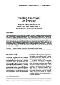
The first case study is parallel particle tracing of the numerical results of a large-eddy simulation of NavierStokes equations for the MAX experiment [28] that recently has become operational at Argonne National Laboratory. The model problem is representative of turbulent mixing and thermal striping that occurs in the upper plenum of liquid sodium fast reactors. The understanding of these phenomena is crucial for increasing the safety and lowering the cost of the next generation power plants. The dataset is courtesy of Aleksandr Obabko and Paul Fischer of Argonne National Laboratory and is generated by the Nek5000 solver. The data have been resampled from their original topology onto a regular grid. Our tests ran for 10 rounds. The top panel of Figure 4 shows the result for a small number of particles, 400 in total. A single time-step of data is used here to model static flow. 1) Scalability: The center panel shows the scalability of larger data size and number of particles. Here, 128 K particles are randomly seeded in the domain. Three sizes of the same thermal hydraulics data are tested: 5123 , 10243 , and 20483 ; the larger sizes were generated by upsampling the original size. All of the times represent end-to-end time including I/O. In the curves for 5123 and 10243 , there is a steep drop from 1 K to 2 K processes. We attribute this to a cache effect because the data size per process is now small enough (6 MB per process in the case of 2 K processes and a 10243 dataset) for it to remain in L3 cache (8 MB on BG/P).
#"
A. Case Study: Thermal Hydraulics
256
512
1024
2048
4096
8192
16384
Number of Processes
Figure 4. The scalability of parallel nearest-neighbor communication for particle tracing of thermal hydraulics data is plotted in log-log scale. The top panel shows 400 particles tracing streamlines in this flow field. In the center panel, 128 K particles are traced in three data sizes: 5123 (134 million cells), 10243 (1 billion cells), and 20483 (8 billion cells). End-toend results are shown, including I/O (reading the vector dataset from storage and writing the output particle traces.) The breakdown of computation and communication time for 128 K particles in a 10243 data volume appears in the lower panel. At smaller numbers of processes, computation is more expensive than communication; the opposite is true at higher process counts.
The lower panel of Figure 4 shows these results broken down into component times for the 10243 dataset, with round-robin partitioning of 4 blocks per process, and 128 K particles. The total time (Total), the total of communication and computation time (Comp+Comm), and individual computation (Comp) and communication (Comm) times are shown. In this example, the region up to 1 K processes is dominated by computation time. From that point on, the fraction of communication grows until, at 16 K processes, communication requires 50% of the total time. 2) Computational Load Balance and Partitioning: Figure 5 shows in more detail the computational load imbalance among processes. The top panel is a visualization using a tool called Jumpshot [29], which shows the activity of individual processes in a format similar to a Gantt chart. Time advances horizontally while process are stacked vertically. This Jumpshot trace is from a run of 128 processes of the 5123 example above, 128 K particles, 4 blocks per process. It clearly shows one process, number 105, spending all of its time computing (magenta) while the other processes spend most of their time waiting (yellow). They are not transmitting particles at this time, merely waiting for process 105; the time spent actually transmitting particles is so small that it is indistinguishable in Figure 5. This nearest-neighbor communication pattern is extremely sensitive to load imbalance because the time that a process spends waiting for another spreads to its neighbors, causing them to wait, and so on, until it covers the entire process space. The four blocks that belong to process 105 are highlighted in red in the center panel of Figure 5. Zooming in on one of the blocks reveals a vortex. This requires the maximum number of integration steps for each round, whereas other particles terminate much earlier. The particle that is in the vortex tends to remain in the same block from one round to the next, forcing the same process to compute longer throughout the program execution. We modified our algorithm so that a particle that is in the same block at the end of the round terminates rather than advancing to the next round. Visually there is no difference because a particle trapped in a critical point has near-zero velocity, but the computational savings are significant. In this same example of 128 processes, making this change decreased the maximum computational time by a factor of 4.4, from 243 s to 55 s, while the other time components remained constant. The overall program execution time decreased by a factor of 3.8, from 256 s to 67 s. The lower panel of Figure 5 shows the improved Jumpshot log. More computation (magenta) is distributed throughout the image, with less waiting time (yellow), although the same process, 105, remains the computational bottleneck. Figure 6 shows the effect of static round-robin partitioning with varying the number of blocks per process, bp. The problem size is 5123 with 8 K particles. We tested bp = 1, 2, 4, 8, and 16 blocks per process. In nearly all cases, the
Figure 5. Top: Jumpshot is used to present a visual log of the time spent in communication (yellow) and computation (magenta). Each horizontal row depicts one process in this test of 128 processes. Process 105 is computationally bound while the other processes spend most of their time waiting for 105. Middle: The four blocks belonging to process 105 are highlighted in red, and one of the four blocks contains a particle trapped in a vortex. Bottom: The same Jumpshot view when particles such as this are terminated after not making progress shows a better distribution of computation across processes, but process 105 is still the bottleneck.
performance improves as bp increases; load is more likely to be distributed evenly and the overhead of managing multiple blocks remains small. There is a limit to the effectiveness of a process having many small blocks as the ratio of blocks’ surface area to volume grows, and we recognize that round-robin distribution does not always produce acceptable load balancing. Randomly seeding a dense set of particles throughout the domain also works in our favor to balance load, but this need not be the case, as demonstrated by Pugmire et al. [11], requiring more sophisticated load balancing
100
Round−Robin Partitioning With Varying Blocks Per Process
!
50
!
! !
!
20
!
TimeSteps
Time Blocks
16 16 32 32 64 64
4 8 4 8 4 8
Static Std.Dev. Steps 31 57 71 121 172 297
Dynamic Std.Dev. Steps 20 28 42 52 103 109
Static Max.Comp. Time(s) 0.15 1.03 0.18 1.12 0.27 1.18
Dynamic Max.Comp. Time(s) 0.14 0.99 0.16 1.06 0.21 1.09
!
10
Time (s)
!
Table I S TATIC ROUND -ROBIN AND DYNAMIC G EOMETRIC PARTITIONING
!
5
!
16
bp = 1 bp = 2 bp = 4 bp = 8 bp = 16
32
64
128
256
512
1024
2048
4096
Number of Processes
Figure 6. The number of blocks per process is varied. Overall time for 8 K particles and a data size of 5123 is shown in log-log scale. Five curves are shown for different partitioning: one block per process and round-robin partitioning with 2, 4, 8, and 16 blocks per process. More blocks per process improve load balance by amortizing computational “hot spots” in the data over more processes.
strategies. In order to compare simple round-robin partitioning with a more complex approach, we implemented Algorithm 3 and prepared a test “time-varying” dataset consisting of 32 repetitions of the same thermal hydraulics time-step, with a 5123 grid size. Ordinarily, we assume that a time series is temporally coherent with little change from one time-step to the next; this test is a degenerate case of temporal coherence where there is no change at all in the data across time-steps. The total number of advection steps is an accurate measure of load balance, as explained in Sections III-A4 and confirmed by the example above, where process 105 indeed computed the maximum number of advection steps, more than three times the average. Table I shows that the result of dynamic repartitioning on 16, 32, and 64 identical timesteps using 256 processes. The standard deviation in the total number of advection steps across processes is better with dynamic repartitioning than with static partitioning of 4 round-robin blocks per process. While computational load measured by total advection steps is better balanced with dynamic repartitioning, our overall execution time is still between 5% and 15% faster with static round-robin partitioning. There is additional cost associated with repartitioning (particle exchange, updating of data structures), and we are currently looking at how to optimize those operations. If we only look at the RungeKutta computation time, however, the last two columns in Table I show that the maximum compute time of the most heavily loaded process improves with dynamic partitioning by 5% to 25%.
In our approach, repartitioning occurs between time blocks. This implies that the number of time blocks, tb, must be large enough so that repartitioning can be performed periodically, but tb must be small enough to have sufficient computation to do in each time block. Another subtle point is that the partition is most balanced at the first time-step of the new time block, which is most similar to the last timestep of the previous time block when the weighting function was computed. The smaller tb is (in other words, the more time-steps per time block) the more likely the new partition will “go out of balance” before it is recomputed. We expect that the infrastructure we have built into our library for computing a new partition using a variety of weighting criteria and partitioning algorithms will be useful for future experiments with static and dynamic load balancing. We have only scratched the surface with this simple partitioning algorithm, and we will continue to experiment with static and dynamic partitioning, for both steady and unsteady flows using our code. B. Case Study: Rayleigh-Taylor Instability The Rayleigh-Taylor instability (RTI) [30] occurs at the interface between a heavy fluid overlying a light fluid, under a constant acceleration, and is of fundamental importance in a multitude of applications ranging from astrophysics to ocean and atmosphere dynamics. The flow starts from rest. Small perturbations at the interface between the two fluids grow to large sizes, interact nonlinearly, and eventually become turbulent. Visualizing such complex structures is challenging because of the extremely large datasets involved. The present dataset was generated by using the variable density version [31] of the CFDNS [32] Navier-Stokes solver and is courtesy of Daniel Livescu and Mark Petersen of Los Alamos National Laboratory. We visualized one checkpoint of the largest resolution available, 2304 × 4096 × 4096, or 432 GB of single-precision, floating-point vector data. Figure 7 shows the results of parallel particle tracing of the RTI dataset on the Intrepid BG/P machine at Argonne National Laboratory. The top panel is a screenshot of 8 K particles, traced by using 8 K processes, and shows turbulent areas in the middle of the mixing region combined with laminar flows above and below. The center and bottom panels show the results of weak and strong scaling tests,
Weak Scaling
Total Comp+Comm Comp.
!
!
24576
32768
500
1000
!
! !
!
12288
16384
100 5
10
20
50
Time (s)
200
!
4096
8192
Number of Processes
C. Case Study: Flame Stabilization
!
!
24576
32768
500
1000
Strong Scaling
! !
!
12288
16384
100 20
50
Time (s)
200
!
Total Comp+Comm Comp.
5
10
!
4096
8192
respectively. Both tests used the same dataset size; we increased the number of particles with the number of processes in the weak scaling regime, while keeping the number of particles constant in strong scaling. Overall weak scaling is good from 4 K through 16 K processes. Strong scaling is poor; the component times indicate that the scalability in computation is eclipsed by the lack of scalability in communication. In fact, the Total and Comp+Comm curves are nearly identical between the weak and strong scaling graphs. This is another indication that at these scales, communication dominates the run time, and the good scalability of the Comp curve does not matter. A steep increase in communication time after 16 K processes is apparent in Figure 7. The size and shape of Intrepid’s 3D torus network depend on the size of the job; in particular, at process counts >16 K, the partition changes from 8 × 16 × 32 nodes to 8 × 32 × 32 nodes. (Recall that 1 node = 4 processes in VN mode.) Thus, it is not surprising for the communication pattern and associated performance to change when the network topology changes, because different process ranks are located in different physical locations on the network. The RTI case study demonstrates that our communication model does not scale well beyond 16 K processes. The main reason is a need for processes to wait for their neighbors, as we saw in Figure 5. Although we are using nonblocking communication, our algorithm is still inherently synchronous, alternating between computation and communication stages. We are investigating ways to relax this restriction based on the results that we have found.
Number of Processes
Figure 7. Top: A combination of laminar and turbulent flow is evident in this checkpoint dataset of RTI mixing. Traces from 8 K particles are rendered using illuminated streamlines. The particles were computed in parallel across 8 K processes from a vector dataset of size 2304 × 4096 × 4096. Center: Weak scaling, total number of particles ranges from 16 K to 128 K. Bottom: Strong scaling, 128K total particles for all process counts.
Our third case study is a simulation of fuel jet combustion in the presence of an external cross-flow [33], [34]. The flame is stabilized in the jet wake, and the formation of vortices at the jet edges enhances mixing. The presence of complex, unsteady flow structures in a large, time-varying dataset make flow visualization challenging. Our dataset was generated by the S3D [35] fully compressible NavierStokes flow solver and is courtesy of Ray Grout of the National Renewable Energy Laboratory and Jacqueline Chen of Sandia National Laboratories. It is a time-varying dataset from which we used 26 time-steps. We replicated the last six time-steps in reverse order for our weak scaling tests to make 32 time-steps total. The spatial resolution of each time-step is 1408 × 1080 × 1100. At 19 GB per time-step, the dataset totals 608 GB. Figure 8 shows the results of parallel particle tracing of the flame dataset on BG/P. The top panel is a screenshot of 512 particles and shows turbulent regions in the interior of the data volume. The bottom panel shows the results of a weak scaling test. We increased the number of time-steps, from 1 time-step at 128 processes to 32 time-steps at 4 K processes. The number of 4D blocks increased accordingly,
Table II O UT- OF -C ORE P ERFORMANCE FOR T IME -VARYING F LAME DATASET No. of Time Blocks 1 2 4 8
!# "#
$#
12')+304
"##
$##
!"#$%&'#()*+
1,9:; !